
Subscribe to Our Youtube Channel
Related Manuals for SKF 800030


Summary of Contents for SKF 800030
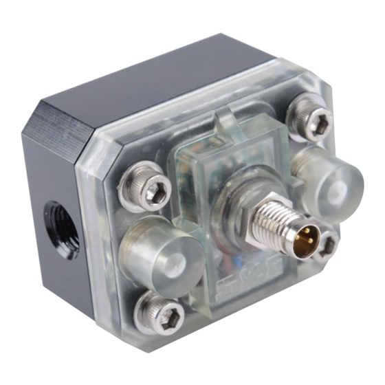
- Page 1 Installation and maintenance guide Digital grease flow detector Model 800030 Date of issue July 2016 400101B Form number Read manual prior to installation or use of this product. Keep manual nearby for future reference.
-
Page 2: Table Of Contents
Table of contents D A N G E R Explanation of safety signals ..Indicates hazardous situation which, if not avoided, will result in death or serious Safety ......injury. -
Page 3: Safety
Application a digital signal to an outside controller. A blinking LED indicates processed signals. Model 800030 was designed to generate a confirmation signal to verify lubrications Notice events of a critical lubrication point. The unit... -
Page 4: Installation
Installation Installation procedure 1 Shut off all grease flow through grease Installation guidelines line. • Units are non-directional. 2 Attach inlet and outlet connections to flow • Use thread sealant on all pipe threads. detector. • Do not overtighten line connections. 3 Attach one end of connector cable to flow •... -
Page 5: Detector Disassembly
Detector disassembly Fig. 1 1 Remove head bolts (2.4) and washers (2.3) Wire pin connections from cover (2.1) († fig. 3). 2 Remove the detector cover (2.1) and Ground Output signal o-ring (1.4). Positive V DC 3 Remove oval gears (1.2, 1.3). 4 Clean and inspect all parts. -
Page 6: Detector Re-Assembly
Detector assembly 4 Place cover (2.1) on detector body (1.1), taking care not to damage o-ring (1.4). 1 Align rib on top of cover (2.1) with “magnet” 5 Install washers and bolts (2.3, 2.4), on body (1.1) († fig. 4). tightening bolts in a diagonal pattern to 2 Insert both gears at 90°... -
Page 7: Service Parts/Kits
Fig. IPB 1 2.3, 1.5 2.4, 1.6 3, 4, 5, 6 Service parts/kits Item no. Pat no. Description 280135 Body assembly kit Body assembly Oval gear Gear with magnet Square o-ring Washer 8-32 x .75 THD-Lock.SHC screw 280136 Cover assembly kit Cover assembly Square o-ring Washer... -
Page 8: Troubleshooting
Troubleshooting* Problem Possible cause Remedy Detector never registers grease No signal from magnet. Check magnets and gear if required. output. Damaged controller/PCB. Replace detector. No grease passed through detector even The system detected a failure correctly lubrication cycle occurred without delivering grease and lubrication device like the injector or to detector’s inlet. - Page 9 Declaration of conformity Declaration of conformity according the EMC directive 2014/30/EU. We declare that the model of the Digital grease flow detector in the version supply by us, com- plies with the provisions of the above men- tioned directive. Applied harmonized standard in particular: EN61326-1 Electrical equipment for meas- urement, control and laboratory use.
-
Page 12: Warranty
This can be found in the General Conditions of Sales, which are available at: www.skf.com/lubrication. ® SKF is a registered trademark of the SKF Group. ® Lincoln is a registered trademark of Lincoln Industrial Corp. © SKF Group 2016...
Need help?
Do you have a question about the 800030 and is the answer not in the manual?
Questions and answers