Table of Contents
Advertisement
Quick Links
Advertisement
Table of Contents

Related Manuals for Supermicro FatTwin AS-F1114S-RNTR


Summary of Contents for Supermicro FatTwin AS-F1114S-RNTR
- Page 1 FatTwin ® AS -F1114S-RNTR USER’S MANUAL Revision 1.0...
- Page 2 State of California, USA. The State of California, County of Santa Clara shall be the exclusive venue for the resolution of any such disputes. Supermicro's total liability for all claims will not exceed the price paid for the hardware product.
- Page 3 If you have any questions, please contact our support team at: support@supermicro.com This manual may be periodically updated without notice. Please check the Supermicro website for possible updates to the manual revision level. Secure Data Deletion A secure data deletion tool designed to fully erase all data from storage devices can be found on our website: https://www.supermicro.com/about/policies/disclaimer.cfm?url=/wdl/utility/...
-
Page 4: Table Of Contents
Preface Contents Chapter 1 Introduction 1.1 Overview ..........................8 1.2 Unpacking the System ......................8 1.3 FatTwin: System Notes ......................9 Nodes ..........................9 System Power ........................9 1.4 System Features ........................10 1.5 Server Features ........................11 Front Features ........................11 Node Control Panels ......................12 Rear Features ........................13 1.6 Motherboard Layout ......................13 Quick Reference Table ......................15 Chapter 2 Server Installation... - Page 5 FatTwin AS -F1114S-RNTR User's Manual Chapter 3 Maintenance and Component Installation 3.1 Removing Power ........................24 Removing System Power ....................24 Removing Power from a Node ..................24 3.2 Chassis Components ......................25 Installing and Removing the Node Drawers ..............25 Removing Nodes from the Chassis ................26 Nodes and Associated Hard Drives ..................27 Installing and Removing 2.5"...
- Page 6 Preface 5.4 IPMI ............................58 BMC ADMIN User Password ....................58 Chapter 6 UEFI BIOS 6.1 Introduction .........................59 Starting the Setup Utility ....................59 6.2 Main Setup .........................60 6.3 Advanced ..........................62 6.4 IPMI ............................82 6.5 Event Logs .........................85 6.6 Security ..........................87 6.7 Boot ............................89 6.8 Save &...
- Page 7 Super Micro Computer, Inc. 980 Rock Ave. San Jose, CA 95131 U.S.A. Tel: +1 (408) 503-8000 Fax: +1 (408) 503-8008 Email: marketing@supermicro.com (General Information) support@supermicro.com (Technical Support) Website: www.supermicro.com Europe Address: Super Micro Computer B.V. Het Sterrenbeeld 28, 5215 ML...
-
Page 8: Overview
FatTwin AS -F1114S-RNTR User's Manual Chapter 1 Introduction 1.1 Overview This chapter provides a brief outline of the functions and features of the AS -F1114S-RNTR. The AS -F1114S-RNTR is based on the H12SSFR-AN6 motherboard and the CSE-F418BC3-R2K20BP chassis. This FatTwin system features eight motherboard tray nodes in the chassis. -
Page 9: Fattwin: System Notes
Chapter 1: Introduction 1.3 FatTwin: System Notes As a FatTwin configuration, the AS -F1114S-RNTR is a unique server system. With eight system boards incorporated into a single chassis acting as eight separate nodes, there are several points you should keep in mind. Nodes Each of the eight motherboards act as a separate node in the system. -
Page 10: System Features
FatTwin AS -F1114S-RNTR User's Manual 1.4 System Features The following table provides you with an overview of the main features of the AS -F1114S-RNTR. Please refer to Appendix B for additional specifications. System Features Motherboard H12SSFR-AN6 Chassis CSE-F418BC3-R2K20BP CPU (per node) Single AMD EPYC™... -
Page 11: Server Features
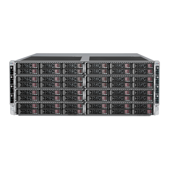
Chapter 1: Introduction 1.5 Server Features Front Features The CSE-F418BC3-R2K20BP is a 4U chassis with eight hot-swap server nodes. See the illustration below for features and logical node locations. Control panels Control panels Figure 1-1. System Front View Front System Features Item Feature Description... -
Page 12: Node Control Panels
FatTwin AS -F1114S-RNTR User's Manual Node Control Panels Each node has its own control panel, with the functions described below. Figure 1-2. Node Control Panel Control Panel Features Item Features Description Applies or removes power from the power supply to the node with standby power Power Button maintained NIC LED... -
Page 13: Rear Features
Chapter 1: Introduction Rear Features The illustration below shows the features included on the rear of the chassis. Figure 1-3. System Rear View Rear System Features Item Feature Description Power Supply Four redundant 2200W power supplies Expansion Slot One PCIe 4.0 x16 expansion card slot I/O Panel I/O ports, see Section 4.3 for details. - Page 14 FatTwin AS -F1114S-RNTR User's Manual USB1 JLAN1 JVGA1 UID_LED JCOM1 LED1 JIPMB1 JDBG1 AIOM JSXB1 JTPM1 JBT1 JPWR_HDD1 I-SATA0 JSXB2 I-SATA1 JNVME2 JSD1 M.2-M2 M.2-M4 JNVME1 JSD2 JNVME4 M.2-M1 M.2-M3 JNVME3 JPWR2 JPWR1 BMC password label JPWR_HDD2 JPWR_HDD3 FAN1 FAN2 FAN3 BATTERY Figure 1-4.
-
Page 15: Quick Reference Table
Chapter 1: Introduction Quick Reference Table Jumper Description Default Setting JBT1 Clear CMOS Open (Normal) JVGA1 VGA Enable/Disable Pins 1-2 (Enabled) JWD1 Watch Dog control Pins 1-2 (Reset) Description Status UID LED Rear unit ID LED Solid blue: UID switched to ON, unit identified LED1 BMC heartbeat LED Green: Blinking (BMC normal), Green: Fast blinking (BMC initializing) - Page 16 FatTwin AS -F1114S-RNTR User's Manual BIOS ROM 32MB P2 [0-15] lane reversal PCIe x16 Slot RJ45 CPU USB2 [2/3] RTL8211F PCIe x16 AST2600 BMC ROM AIOM P3 [9] P1 [0-15] 32MB PCIe x16 SlimSAS x4 *2 P0 [0-7] SATA x8 AMD SP3 G0 [0-3] M.2 PCIe x4 / SATA...
-
Page 17: Chapter 2 Server Installation
Chapter 2: Server Installation Chapter 2 Server Installation 2.1 Overview This chapter provides advice and instructions for mounting your system in a server rack. If your system is not already fully integrated with processors, system memory etc., refer to Chapter 4 for details on installing those specific components. Caution: Electrostatic Discharge (ESD) can damage electronic components. -
Page 18: Server Precautions
FatTwin AS -F1114S-RNTR User's Manual • In single rack installations, stabilizers should be attached to the rack. In multiple rack in- stallations, the racks should be coupled together. • Always make sure the rack is stable before extending a server or other component from the rack. -
Page 19: Circuit Overloading
Chapter 2: Server Installation Note: Insert the nodes into the chassis from the bottom left to bottom right and then up all the way to the top (left first, then right). Do not insert the nodes on one side fully (leaving one side empty) and then the other side or it will be very hard to insert the last node. -
Page 20: Rack Mounting Instructions
FatTwin AS -F1114S-RNTR User's Manual 2.3 Rack Mounting Instructions This section provides information on installing the chassis into a rack unit with the rails provided. There are a variety of rack units on the market, which may mean that the assembly procedure will differ slightly from the instructions provided. -
Page 21: Identifying The Sections Of The Rack Rails
Chapter 2: Server Installation Identifying the Sections of the Rack Rails The chassis package includes two rail assemblies in the rack mounting kit. Each assembly consists of two sections: A front section which secures to the front post of the rack and a rear section which adjusts in length and secures to the rear post of the rack. -
Page 22: Installing The Rails On A Rack
FatTwin AS -F1114S-RNTR User's Manual Installing the Rails on a Rack Installing the Rails 1. Adjust the length of both rails as described on the previous page. 2. Align the front section of the outer rail with the slots on the front post of the rack. Secure the front of the outer rail to the rack with two screws. -
Page 23: Chassis Installation
Chapter 2: Server Installation Chassis Installation Installing the Chassis into a Rack 1. Confirm that the rails are correctly installed on the rack. 2. Align the bottom of the chassis with the bottom of the rails. 3. Insert the chassis into the AS -F1114S-RNTR rails, keeping the pressure even on both sides, pushing the chassis into the rack until it clicks into the locked position. -
Page 24: Chapter 3 Maintenance And Component Installation
FatTwin AS -F1114S-RNTR User's Manual Chapter 3 Maintenance and Component Installation This chapter provides instructions on installing and replacing main system components. To prevent compatibility issues, only use components that match the specifications and/or part numbers given. Installation or replacement of most components require that power first be removed from the system. -
Page 25: Chassis Components
Chapter 3: Maintenance and Component Installation 3.2 Chassis Components The chassis includes power supplies, fans and eight nodes. Each node is a separate system containing a drawer with a motherboard and other components. Each node may be removed from the chassis separately. Installing and Removing the Node Drawers The CSE-F418BC3 chassis contains eight individual motherboards in separate node drawers (Figure 3-1). -
Page 26: Removing Nodes From The Chassis
FatTwin AS -F1114S-RNTR User's Manual Removing Nodes from the Chassis Each of the eight individual nodes may be removed from the chassis separately. Note that when a node is removed from the chassis, the hard drives located in the node will lose power and shut down. -
Page 27: Nodes And Associated Hard Drives
Chapter 3: Maintenance and Component Installation Nodes and Associated Hard Drives The CSE-F418BC3 chassis contains up to eight individual motherboards in separate 1U nodes. Each node can support two NVMe/SATA + four SATA 2.5" drives per node (NVMe support optional). Note that if a node is pulled out of the chassis, the hard drives associated with that node will power down as well. - Page 28 FatTwin AS -F1114S-RNTR User's Manual 3. Remove the screws securing the hard drive to the tray and set them aside for later use. Figure 3-4. Installing a Hard Drive in the Drive Carrier 4. Lift the hard drive out of the tray. 5.
-
Page 29: Installing Expansion Cards
Chapter 3: Maintenance and Component Installation Installing Expansion Cards Each of the eight nodes in the chassis has space for two low-profile expansion cards mounted in the front of the node. The following instructions are for chassis nodes in which the expansion cards are mounted in the rear of the node. - Page 30 FatTwin AS -F1114S-RNTR User's Manual Figure 3-7. Installing the Expansion Card and Bracket...
-
Page 31: Installing Air Shrouds
Chapter 3: Maintenance and Component Installation Installing Air Shrouds Air shrouds concentrate airflow to maximize fan efficiency. The CSE-F418BC3 chassis require an air shroud in each node. Installing an Air Shroud 1. Remove the node from the chassis and remove the cover from the node as described previously in this section. -
Page 32: Removing And Installing System Fans
FatTwin AS -F1114S-RNTR User's Manual Removing and Installing System Fans Each node in the system has three counter-rotating fans. Remove the failed fan's wiring from the motherboard. Begin by identifying the failed fan and powering down the node it resides in. Removing and Installing System Fans 1. -
Page 33: Replacing The Power Supplies
Power Supply Replacement In the event that any of the power supply units need to be replaced, it can be removed without powering down the system. Replacement units can be ordered directly from Supermicro. Changing the Power Supply 1. Disconnect the AC power cord on the back of the failed power supply unit. -
Page 34: Motherboard Components
When receiving a motherboard without a processor pre-installed, make sure that the plastic CPU socket cap is in place and none of the socket pins are bent; otherwise, contact your retailer immediately. • Refer to the Supermicro website for updates on CPU support. - Page 35 Chapter 3: Maintenance and Component Installation Installing the Processor and Heatsink 1. Unscrew the screws holding down Force Frame in the sequence of 3-2-1. The screws are numbered on the Force Frame next to each screw hole. Screw #3 Screw #1 Screw #2 Force Frame 2.
- Page 36 FatTwin AS -F1114S-RNTR User's Manual 3. Lift the Rail Frame up by gripping the lift tabs near the front end of the rail frame. While keeping a secure grip of the Rail Frame, lift it to a position so you can do the next step of removing the External Cap.
- Page 37 Chapter 3: Maintenance and Component Installation 5. The CPU Package is shipped from the factory with the Carrier Frame pre-assembled. Grip the handle of the Carrier Frame/CPU Package assembly from its shipping tray, and while gripping the handle, align the flanges of the Carrier Frame onto the rails of the Rail Frame so its pins will be at the bottom when the Rail Frame is lowered later.
- Page 38 FatTwin AS -F1114S-RNTR User's Manual 8. Gently lower the Rail Frame down onto the socket until the latches on the Rail Frame engage with the Socket housing. and it rests in place. DO NOT force it into place! 9. Gently lower the Force Frame down onto the Rail Frame and hold it in place until it is seated in the Socket housing.
- Page 39 Chapter 3: Maintenance and Component Installation 1. After the Force Frame is secured and the CPU package is in place, now you must install the heatsink to the frame. Lower the heatsink down till it rests securely over the four screw holes on CPU Package on the socket frame.
- Page 40 FatTwin AS -F1114S-RNTR User's Manual Un-installing the Processor and Heatsink 1. Remove the heatsink attached to the top of the CPU Package by reversing the installation procedure. 2. Clean the Thermal grease left by the heatsink on the CPU package lid to limit the risk of it contaminating the CPU package land pads or contacts in the socket housing.
-
Page 41: Memory Support And Installation
Chapter 3: Maintenance and Component Installation 3.4 Memory Support and Installation Note: Check the Supermicro website for recommended memory modules. Important: Exercise extreme care when installing or removing DIMM modules to prevent any possible damage. Memory Support The H12SSFR-AN6 supports up to 2TB registered ECC DDR4-3200 memory in 8 DIMM slots. -
Page 42: Dimm Module Population
FatTwin AS -F1114S-RNTR User's Manual DIMM Module Population There is no specific order or sequence required when installing memory modules. However do keep the following in mind: • It is recommended that you use DDR4 DIMM modules of the same type, size and speed. •... -
Page 43: Dimm Installation
Chapter 3: Maintenance and Component Installation DIMM Installation 1. Insert the desired number of DIMMs into the memory slots, there is no specific sequence or order required. Receptive 2. Push the release tabs outwards on both Point ends of the DIMM slot to unlock it. 3. -
Page 44: Motherboard Battery
FatTwin AS -F1114S-RNTR User's Manual Motherboard Battery The motherboard uses non-volatile memory to retain system information when system power is removed. This memory is powered by a lithium battery residing on the motherboard. Replacing the Battery Begin by removing power from the system as described in section 3.1. 1. -
Page 45: Chapter 4 Motherboard Connections
Chapter 4: Motherboard Connections Chapter 4 Motherboard Connections This section describes the connections on the motherboard and provides pinout definitions. Note that depending on how the system is configured, not all connections are required. The LEDs on the motherboard are also described here. A motherboard layout indicating component locations may be found in Chapter 1. -
Page 46: Headers And Connectors
FatTwin AS -F1114S-RNTR User's Manual HDD/SSD Power Connectors JPWR_HDD1 ~ JPWR_HDD3 are used to provide power to the onboard HDD/SSD ports. Refer to the table below for pin definitions. HDD/SSD Power Connector Pin Definitions Pins Definition Ground Ground +12V 4.2 Headers and Connectors Onboard Fan Headers There are three fan headers on the motherboard. - Page 47 It enables the motherboard to deny access if the TPM associated with the hard drive is not installed in the system. Please go to the following link for more information on TPM: http://www.supermicro.com/ manuals/other/TPM.pdf. Trusted Platform Module Header...
- Page 48 JF1 contains header pins for various buttons and indicators that are normally located on a control panel at the front of the chassis. This connector is designed specifically for use with Supermicro chassis and connects to the motherboard with Supermicro cable p/n CBL-OTHR- 0022L. See the figure below for the pin definitions of JF1.
-
Page 49: Rear I/O Ports
Chapter 4: Motherboard Connections 4.3 Rear I/O Ports See the figure below for the locations and descriptions of the various I/O ports on the rear of the motherboard. Figure 4-2. Rear I/O Port Locations Rear I/O Ports Description Description VGA Port USB0 Port (USB 3.0) LAN1 Port USB1 Port (USB 3.0) - Page 50 Note: UID can be triggered with the onboard UID switch or via IPMI. For more information on IPMI, please refer to the IPMI User's Guide posted on our website at http://www.supermicro.
-
Page 51: Jumpers
Chapter 4: Motherboard Connections 4.4 Jumpers Explanation of Jumpers To modify the operation of the motherboard, jumpers are used to choose between optional settings. Jumpers create shorts between two pins to change the function associated with it. Pin 1 is identified with a square solder pad on the printed circuit board. See the motherboard layout page for jumper locations. - Page 52 FatTwin AS -F1114S-RNTR User's Manual VGA Enable/Disable (JVGA1) JVGA1 allows you to enable or disable the VGA port. The default position is on pins 1 and 2 to enable VGA. See the table below for jumper settings. VGA Enable/Disable Jumper Settings (JVGA1) Jumper Setting Definition Pins 1-2...
-
Page 53: Led Indicators
Chapter 4: Motherboard Connections 4.5 LED Indicators LAN Port LEDs The motherboard's Ethernet port has two LED indicators. The Activity LED is yellow and indicates connection and activity. The Link LED may be green, amber, or off to indicate the speed of the connection. -
Page 54: Chapter 5 Software
USB/SATA DVD drive, or a USB flash drive, or the IPMI KVM console. 2. Go to the Supermicro web page for your motherboard and click on "Download the Latest Drivers and Utilities", select the proper driver, and copy it to a USB flash drive. - Page 55 Chapter 5: Software 4. During Windows Setup, continue to the dialog where you select the drives on which to install Windows. If the disk you want to use is not listed, click on “Load driver” link at the bottom left corner. Figure 5-2.
-
Page 56: Driver Installation
The Supermicro website contains drivers and utilities for your system at https://www. supermicro.com/wdl/driver. Some of these must be installed, such as the chipset driver. After accessing the website, go into the CDR_Images (in the parent directory of the above link) and locate the ISO file for your motherboard. Download this file to to a USB flash drive or a DVD. -
Page 57: Superdoctor 5
5.3 SuperDoctor ® The Supermicro SuperDoctor 5 is a program that functions in a command-line or web-based interface for Windows and Linux operating systems. The program monitors such system health information as CPU temperature, system voltages, system power consumption, fan speed, and provides alerts via email or Simple Network Management Protocol (SNMP). -
Page 58: Ipmi
BIOS settings that are related to IPMI. For general documentation and information on IPMI, visit our website at: http://www.supermicro.com/products/nfo/IPMI.cfm. BMC ADMIN User Password For security, each system is assigned a unique default BMC password for the ADMIN user. -
Page 59: Chapter 6 Uefi Bios
Chapter 6: UEFI BIOS Chapter 6 UEFI BIOS 6.1 Introduction This chapter describes the AMIBIOS™ Setup utility for H12SSFR-AN6 motherboards that are equipped with the EPYC 7003 or 7002 Series Processor. The BIOS is stored on a chip and can be easily upgraded using a flash program. Note: Due to periodic changes to the BIOS, some settings may have been added or deleted and might not yet be recorded in this manual. -
Page 60: Main Setup
Note: The time is in the 24-hour format. For example, 5:30 P.M. appears as 17:30:00. The date's default value is 01/01/2015 after RTC reset. Supermicro H12SSFR-AN6 BIOS Version This item displays the version of the BIOS ROM used in the system. - Page 61 Chapter 6: UEFI BIOS Build Date This item displays the date when the version of the BIOS ROM used in the system was built. CPLD Version This item displays the CPLD version of the BIOS ROM used in the system. Memory Information Total Memory This feature displays the total system memory detected.
-
Page 62: Advanced
FatTwin AS -F1114S-RNTR User's Manual 6.3 Advanced Use the arrow keys to select a top item and press <Enter> to access the submenu items. Warning: Take caution when changing the Advanced settings. An incorrect value, a very high DRAM frequency, or an incorrect DRAM timing setting may make the system unstable. - Page 63 Chapter 6: UEFI BIOS Bootup NumLock State Use this feature to set the Power on state for the <Numlock> key. The options are On and Off. Wait For "F1" If Error Use this feature to force the system to wait until the 'F1' key is pressed if an error occurs. The options are Disabled and Enabled.
- Page 64 FatTwin AS -F1114S-RNTR User's Manual Trusted Computing Security Device Support If this feature and the TPM jumper on the motherboard are both set to Enabled, onboard security devices will be enabled for TPM (Trusted Platform Module) support to enhance data integrity and network security.
- Page 65 Chapter 6: UEFI BIOS ACPI SRAT L3 Cache As NUMA Domain Use this setting to enable/disable ACPI SRAT L3 Cache As NUMA Domain. The options are Disabled, Enabled, and Auto. Super IO Configuration The following Super IO information will display: •...
- Page 66 FatTwin AS -F1114S-RNTR User's Manual Serial Port Console Redirection COM1 Console Redirection Select Enabled to enable console redirection support for a serial port specified by the user. The options are Disabled and Enabled. *If the item above set to Enabled, the following items will become available for user's configuration: Console Redirection Settings Terminal Type...
- Page 67 Chapter 6: UEFI BIOS Flow Control Use this feature to set the flow control for Console Redirection to prevent data loss caused by buffer overflow. Send a "Stop" signal to stop sending data when the receiving buffer is full. Send a "Start" signal to start sending data when the receiving buffer is empty. The options are None and Hardware RTS/CTS.
- Page 68 FatTwin AS -F1114S-RNTR User's Manual *If the item above set to Enabled, the following items will become available for user's configuration: Console Redirection Settings Terminal Type This feature allows the user to select the target terminal emulation type for Console Redirection.
- Page 69 Chapter 6: UEFI BIOS VT-UTF8 Combo Key Support Select Enabled to enable VT-UTF8 Combination Key support for ANSI/VT100 terminals. The options are Disabled and Enabled. Recorder Mode Select Enabled to capture the data displayed on a terminal and send it as text messages to a remote server.
- Page 70 FatTwin AS -F1114S-RNTR User's Manual Console Redirection Settings Out-of-Band Mgmt Port The feature selects a serial port in a client server to be used by the Microsoft Windows Emergency Management Services (EMS) to communicate with a remote host server. The options are COM1 and SOL.
- Page 71 Chapter 6: UEFI BIOS CPU Configuration SMT Control Use this setting to specify Simultaneous Multithreading. The options are Disabled and Auto. Core Performance Boost This setting is used to configure for Core Performance Boost. Options include Disabled and Auto. Global C-state Control This setting is used to configure for Global C-state Control.
- Page 72 FatTwin AS -F1114S-RNTR User's Manual CPU Configuration SMT Control Used to enable or disable symmetric multithreading. To re-enable SMT, a power cycle is needed after selecting the Auto option. Warning - S3 is not supported on systems where SMT is disabled. The options include Auto and Disabled. Core Performance Boost Use to enable a core performance boost.
- Page 73 Chapter 6: UEFI BIOS CPU Information These sections are for informational purposes. They will display some details about the detected CPUs on the motherboard, such as: • CPU Version • Number of Cores Running • Processor Family • Processor Model •...
- Page 74 FatTwin AS -F1114S-RNTR User's Manual Memory Configuration Memory Clock This setting allows you to select different memory clock speed. Options include Auto and supported frequencies. Memory Interleaving This setting controls fabric level memory interleaving. Note that the channel, die and socket have requirements on memory populations and it will be ignored if the memory doesn't support the selected option.
- Page 75 Chapter 6: UEFI BIOS SR-IOV Support If the system has SR-IOV capable PCI-E devices, this setting will Disable or Enable the Single Root IO Virtualization Support for the system. BME DMA Mitigation Use this setting to re-enable the Bus Master Attribute that was disabled during PCI enumeration for PCI bridges after SMM is locked.
- Page 76 FatTwin AS -F1114S-RNTR User's Manual PCI-E M.2-M3 OPROM This setting enables or disables the PCIe M.2-M3 OPROM option. The options include Disabled or Legacy. PCI-E M.2-M4 OPROM This setting enables or disables the PCIe M.2-M4 OPROM option. The options include Disabled or Legacy.
- Page 77 Chapter 6: UEFI BIOS Onboard NVMe8 Option ROM Select which firmware function is to be loaded for onboard NVMe8. The options include Disabled and Legacy. Onboard Video Option ROM Select Legacy to boot the system using a legacy video device installed on the motherboard. The options include Disabled and Legacy.
- Page 78 FatTwin AS -F1114S-RNTR User's Manual XHCI Hand-Off This is a work-around solution for operating systems that do not support XHCI (Extensible Host Controller Interface) hand-off. The XHCI ownership change should be claimed by the XHCI driver. The options are Enabled, and Disabled. Port 60/64 Emulation Select Enabled for I/O port 60h/64h emulation support, which in turn, will provide complete legacy USB keyboard support for the operating systems that do not support legacy USB...
- Page 79 Chapter 6: UEFI BIOS KMS TLS Certifiicate CA Certificate Client Certificate Client Private Key The options are Update, Delete and Export. HTTP Boot Configuration HTTP Boot Policy Sets the HTTP boot policy to Apply to all LANs, Apply to each LAN, or Boot Priority #1 instantly.
- Page 80 FatTwin AS -F1114S-RNTR User's Manual (Dynamic Host Configuration Protocol) server in the network that it is attached to and request the next available IP address for this computer. The options are Enabled and Disabled. *If the item above is set to Disabled, the following items will become available for configuration: Local IP Address This item sets and displays the Local IP address for this computer.
- Page 81 Chapter 6: UEFI BIOS Certification GUID Use this feature to input the certification GUID. Commit Changes and Exit Use this feature to save all changes and exit TLS settings. Discard Changes and Exit Use this feature to discard all changes and exit TLS settings. Delete Certification Use this feature to delete certification.
-
Page 82: Ipmi
FatTwin AS -F1114S-RNTR User's Manual 6.4 IPMI This tab allows you to configure the following IPMI settings for the system. Use this feature to configure Intelligent Platform Management Interface (IPMI) settings. BMC Firmware Revision This item indicates the IPMI firmware revision used in your system. IPMI STATUS This item indicates the status of the IPMI firmware installed in your system. - Page 83 Chapter 6: UEFI BIOS Erasing Settings Erase SEL Select Yes, On next reset to erase all system event logs upon next system reboot. Select Yes, On every reset to erase all system event logs upon each system reboot. Select No to keep all system event logs after each system reboot.
- Page 84 FatTwin AS -F1114S-RNTR User's Manual Station MAC Address This item displays the Station MAC address for this computer. Mac addresses are 6 two- digit hexadecimal numbers. Gateway IP Address This item displays the Gateway IP address for this computer. This should be in decimal and in dotted quad form (i.e., 172.31.0.1).
-
Page 85: Event Logs
Chapter 6: UEFI BIOS 6.5 Event Logs This tab allows the user to configure the following event logs settings for the system. Enabling/Disabling Options SMBIOS Event Log Select Enabled to enable SMBIOS (System Management BIOS) Event Logging during system boot. The options are Disabled and Enabled. Erasing Settings Erase Event Log Select Yes to erase all error events in the SMBIOS (System Management BIOS) log before... - Page 86 FatTwin AS -F1114S-RNTR User's Manual When Log is Full Select Erase Immediately to immediately erase all errors in the SMBIOS event log when the event log is full. Select Do Nothing for the system to do nothing when the SMBIOS event log is full.
-
Page 87: Security
Chapter 6: UEFI BIOS 6.6 Security This tab allows you to configure the following security settings for the system. Administrator Password Press Enter to create a new, or change an existing Administrator password. Note that if the Administrator Password is erased, the User Password will be cleared as well. Password Check Select Setup for the system to check for a password at Setup. - Page 88 FatTwin AS -F1114S-RNTR User's Manual Secure Boot The Secure Boot function is active if Secure Boot is enabled. Platform K (PK) is enrolled and the system is in user mode. The mode change requires a platform reset. Options are Enabled and Disabled. Secure Boot Mode In Custom Mode, secure boot policy variables can be configured by a physically present user without full authentication.
-
Page 89: Boot
Chapter 6: UEFI BIOS 6.7 Boot Use this tab to configure Boot Settings: Boot Mode Select Use this item to select the type of device that the system is going to boot from. The options are Legacy, UEFI, and Dual. LEGACY to EFI Support This option Disables or Enables the system to boot to an EFI OS after the boot failed from the legacy boot order. - Page 90 FatTwin AS -F1114S-RNTR User's Manual Delete Boot Option Use this feature to remove a pre-defined boot device from which the system will boot during startup. The settings are [any pre-defined boot device] and UEFI: Built-in EFI shell. UEFI Application Boot Priorities This feature allows the user to specify which UEFI devices are boot devices.
-
Page 91: Save & Exit
Chapter 6: UEFI BIOS 6.8 Save & Exit Select the Save & Exit tab to enter the Save & Exit BIOS Setup screen. Save Options Discard Changes and Exit Select this option to quit the BIOS Setup without making any permanent changes to the system configuration, and reboot the computer. - Page 92 FatTwin AS -F1114S-RNTR User's Manual Discard Changes Select this option and press <Enter> to discard all the changes and return to the AMI BIOS utility Program. Default Options Restore Optimized Defaults To set this feature, select Restore Optimized Defaults from the Save & Exit menu and press <Enter>.
-
Page 93: Appendix A Standardized Warning Statements For Ac Systems
Supermicro's Technical Support department for assistance. Only certified technicians should attempt to install or configure components. Read this appendix in its entirety before installing or configuring components in the Supermicro chassis. These warnings may also be found on our website at http://www.supermicro.com/about/... - Page 94 Appendix A: Standardized Warning Statements Warnung WICHTIGE SICHERHEITSHINWEISE Dieses Warnsymbol bedeutet Gefahr. Sie befinden sich in einer Situation, die zu Verletzungen führen kann. Machen Sie sich vor der Arbeit mit Geräten mit den Gefahren elektrischer Schaltungen und den üblichen Verfahren zur Vorbeugung vor Unfällen vertraut. Suchen Sie mit der am Ende jeder Warnung angegebenen Anweisungsnummer nach der jeweiligen Übersetzung in den übersetzten Sicherheitshinweisen, die zusammen mit diesem Gerät ausgeliefert wurden.
- Page 95 FatTwin AS -F1114S-RNTR User's Manual . ٌ ا ك ً ف حالة و ٌ يك أى تتسبب ف اصابة جسذ ة ٌ هذا الزهز ع ٌ خطز !تحذ ز قبل أى تعول عىل أي هعذات،يك عىل علن بالوخاطز ال ا ٌجوة عي الذوائز ٍ...
- Page 96 Appendix A: Standardized Warning Statements Warnung Vor dem Anschließen des Systems an die Stromquelle die Installationsanweisungen lesen. ¡Advertencia! Lea las instrucciones de instalación antes de conectar el sistema a la red de alimentación. Attention Avant de brancher le système sur la source d'alimentation, consulter les directives d'installation. .יש...
- Page 97 FatTwin AS -F1114S-RNTR User's Manual Warnung Dieses Produkt ist darauf angewiesen, dass im Gebäude ein Kurzschluss- bzw. Überstromschutz installiert ist. Stellen Sie sicher, dass der Nennwert der Schutzvorrichtung nicht mehr als: 250 V, 20 A beträgt. ¡Advertencia! Este equipo utiliza el sistema de protección contra cortocircuitos (o sobrecorrientes) del edificio.
- Page 98 Appendix A: Standardized Warning Statements Power Disconnection Warning Warning! The system must be disconnected from all sources of power and the power cord removed from the power supply module(s) before accessing the chassis interior to install or remove system components. 電源切断の警告...
- Page 99 FatTwin AS -F1114S-RNTR User's Manual אזהרה מפני ניתוק חשמלי !אזהרה יש לנתק את המערכת מכל מקורות החשמל ויש להסיר את כבל החשמלי מהספק .לפני גישה לחלק הפנימי של המארז לצורך התקנת או הסרת רכיבים يجب فصم اننظاو من جميع مصادر انطاقت وإ ز انت سهك انكهرباء من وحدة امداد انطاقت...
- Page 100 Appendix A: Standardized Warning Statements Attention Il est vivement recommandé de confier l'installation, le remplacement et la maintenance de ces équipements à des personnels qualifiés et expérimentés. !אזהרה .צוות מוסמך בלבד רשאי להתקין, להחליף את הציוד או לתת שירות עבור הציוד واملدربيه...
- Page 101 FatTwin AS -F1114S-RNTR User's Manual Warnung Diese Einheit ist zur Installation in Bereichen mit beschränktem Zutritt vorgesehen. Der Zutritt zu derartigen Bereichen ist nur mit einem Spezialwerkzeug, Schloss und Schlüssel oder einer sonstigen Sicherheitsvorkehrung möglich. ¡Advertencia! Esta unidad ha sido diseñada para instalación en áreas de acceso restringido. Sólo puede obtenerse acceso a una de estas áreas mediante la utilización de una herramienta especial, cerradura con llave u otro medio de seguridad.
- Page 102 Appendix A: Standardized Warning Statements Battery Handling Warning! There is the danger of explosion if the battery is replaced incorrectly. Replace the battery only with the same or equivalent type recommended by the manufacturer. Dispose of used batteries according to the manufacturer's instructions 電池の取り扱い...
- Page 103 FatTwin AS -F1114S-RNTR User's Manual هناك خطر من انفجار يف حالة اسحبذال البطارية بطريقة غري صحيحة فعليل اسحبذال البطارية فقط بنفس النىع أو ما يعادلها مام أوصث به الرشمة املصنعة جخلص من البطاريات املسحعملة وفقا لحعليامت الرشمة الصانعة 경고! 배터리가 올바르게 교체되지 않으면 폭발의 위험이 있습니다. 기존 배터리와 동일하거나 제 조사에서...
- Page 104 Appendix A: Standardized Warning Statements ¡Advertencia! Puede que esta unidad tenga más de una conexión para fuentes de alimentación. Para cortar por completo el suministro de energía, deben desconectarse todas las conexiones. Attention Cette unité peut avoir plus d'une connexion d'alimentation. Pour supprimer toute tension et tout courant électrique de l'unité, toutes les connexions d'alimentation doivent être débranchées.
- Page 105 FatTwin AS -F1114S-RNTR User's Manual Backplane Voltage Warning! Hazardous voltage or energy is present on the backplane when the system is operating. Use caution when servicing. バックプレーンの電圧 システムの稼働中は危険な電圧または電力が、 バックプレーン上にかかっています。 修理する際には注意く ださい。 警告 当系统正在进行时,背板上有很危险的电压或能量,进行维修时务必小心。 警告 當系統正在進行時,背板上有危險的電壓或能量,進行維修時務必小心。 Warnung Wenn das System in Betrieb ist, treten auf der Rückwandplatine gefährliche Spannungen oder Energien auf.
- Page 106 Appendix A: Standardized Warning Statements هناك خطز مه التيار الكهزبايئ أوالطاقة املىجىدة عىل اللىحة عندما يكىن النظام يعمل كه حذ ر ا عند خدمة هذا الجهاس 경고! 시스템이 동작 중일 때 후면판 (Backplane)에는 위험한 전압이나 에너지가 발생 합니다. 서비스 작업 시 주의하십시오. Waarschuwing Een gevaarlijke spanning of energie is aanwezig op de backplane wanneer het systeem in gebruik is.
- Page 107 FatTwin AS -F1114S-RNTR User's Manual תיאום חוקי החשמל הארצי !אזהרה .התקנת הציוד חייבת להיות תואמת לחוקי החשמל המקומיים והארציים تركيب املعدات الكهربائية يجب أن ميتثل للقىاويه املحلية والىطىية املتعلقة بالكهرباء 경고! 현 지역 및 국가의 전기 규정에 따라 장비를 설치해야 합니다. Waarschuwing Bij installatie van de apparatuur moet worden voldaan aan de lokale en nationale elektriciteitsvoorschriften.
- Page 108 Appendix A: Standardized Warning Statements Attention La mise au rebut ou le recyclage de ce produit sont généralement soumis à des lois et/ou directives de respect de l'environnement. Renseignez-vous auprès de l'organisme compétent. סילוק המוצר !אזהרה .סילוק סופי של מוצר זה חייב להיות בהתאם להנחיות וחוקי המדינה التخلص...
- Page 109 FatTwin AS -F1114S-RNTR User's Manual Warnung Gefährlich Bewegende Teile. Von den bewegenden Lüfterblätter fern halten. Die Lüfter drehen sich u. U. noch, wenn die Lüfterbaugruppe aus dem Chassis genommen wird. Halten Sie Finger, Schraubendreher und andere Gegenstände von den Öffnungen des Lüftergehäuses entfernt.
- Page 110 Verbindungskabeln, Stromkabeln und/oder Adapater, die Ihre örtlichen Sicherheitsstandards einhalten. Der Gebrauch von anderen Kabeln und Adapter können Fehlfunktionen oder Feuer verursachen. Die Richtlinien untersagen das Nutzen von UL oder CAS zertifizierten Kabeln (mit UL/CSA gekennzeichnet), an Geräten oder Produkten die nicht mit Supermicro gekennzeichnet sind.
- Page 111 .قيرح وأ لطع يف ببستي دق ىرخأ تالوحمو تالباك يأ مادختسا .ميلسلا سباقلاو لصوملا مجح لبق نم ةدمتعملا تالباكلا مادختسا تادعملاو ةيئابرهكلا ةزهجألل ةمالسلا نوناق رظحيUL وأCSA ( ةمالع لمحت يتلاوUL/CSA) لبق نم ةددحملاو ةينعملا تاجتنملا ريغ ىرخأ تادعم يأ عمSupermicro.
- Page 112 사항을 준수하여 제공되거나 지정된 연결 혹은 구매 케이블, 전원 케이블 및 AC 어댑터를 사용하십시오. 다른 케이블이나 어댑터를 사용하면 오작동이나 화재가 발생할 수 있습니다. 전기 용품 안전법은 UL 또는 CSA 인증 케이블 (코드에 UL / CSA가 표시된 케이블)을 Supermicro 가 지정한 제품 이외의 전기 장치에 사용하는 것을 금지합니다. Stroomkabel en AC-Adapter...
-
Page 113: Appendix B System Specifications
Appendix B: System Specifications Appendix B System Specifications Processors Dual AMD EPYC™ 7003/7002 Series processors in Socket SP3 type sockets for each node. Notes: AMD EPYC 7003 series processor support requires BIOS version 2.0 or newer. Please refer to the product page on our website for updates to supported processors. - Page 114 FatTwin AS -F1114S-RNTR User's Manual Operating Environment Operating Temperature: 0º to 35º C (50º to 95º F) Non-operating Temperature: -40º to 60º C (-40º to 140º F) Operating Relative Humidity: 8% to 90% (non-condensing) Non-operating Relative Humidity: 5 to 95% (non-condensing) Regulatory Compliance FCC, ICES, CE, VCCI, RCM, UKCA, NRTL, CB Applied Directives, Standards...
-
Page 115: Appendix C Uefi Bios Recovery
Warning: Do not upgrade the BIOS unless your system has a BIOS-related issue. Flashing the wrong BIOS can cause irreparable damage to the system. In no event shall Supermicro be liable for direct, indirect, special, incidental, or consequential damages arising from a BIOS update. - Page 116 Note: If you cannot locate the "Super.ROM" file in your drive disk, visit our website at www. supermicro.com to download the BIOS package. Extract the BIOS binary image into a USB flash device and rename it "Super.ROM" for the BIOS recovery use.
- Page 117 Appendix C: UEFI BIOS Recovery 3. After locating the healthy BIOS binary image, the system will enter the BIOS Recovery menu as shown below. Note: At this point, you may decide if you want to start the BIOS recovery. If you decide to proceed with BIOS recovery, follow the procedures below.
- Page 118 FatTwin AS -F1114S-RNTR User's Manual 5. After the BIOS recovery process is complete, press any key to reboot the system. 6. Using a different system, extract the BIOS package into a USB flash drive. 7. Press <Del> continuously during system boot to enter the BIOS Setup utility. From the top of the tool bar, select Boot to enter the submenu.
- Page 119 Appendix C: UEFI BIOS Recovery 8. When the UEFI Shell prompt appears, type fs# to change the device directory path. Go to the directory that contains the BIOS package you extracted earlier from Step 6. Enter flash.nsh BIOSname.### at the prompt to start the BIOS update process. Note: Do not interrupt this process until the BIOS flashing is complete.
Need help?
Do you have a question about the FatTwin AS-F1114S-RNTR and is the answer not in the manual?
Questions and answers