Advertisement
Quick Links
INSTALLATION AND MAINTENANCE INSTRUCTIONS
B300A-6 and B300A-6-IV
6" Plug-in Detector Bases
SPECIFICATIONS
Base Diameter:
Base Height:
Operating Temperature:
Electrical Ratings:
Operating Voltage:
Standby Current:
Listings: ULC S529
BEFORE INSTALLING
Please read the System Smoke Detectors Application Guide, which provides
detailed information on detector spacing, placement, zoning, wiring, and spe-
cial applications. Copies of this application guide are available from System
Sensor. CAN/ULC S524 guidelines should be observed.
NOTICE: This manual should be left with the owner/user of this equipment.
IMPORTANT: The detector used with this base must be tested and main-
tained regularly following CAN/ULC S536 requirements. The detector should
be cleaned at least once a year.
GENERAL DESCRIPTION
The B300A-6 and B300A-6-IV are plug-in detector bases intended for use in an
intelligent system, with screw terminals provided for power (+ and –), and
remote annunciator connections. Communication takes place over the power
lines (+ and –).
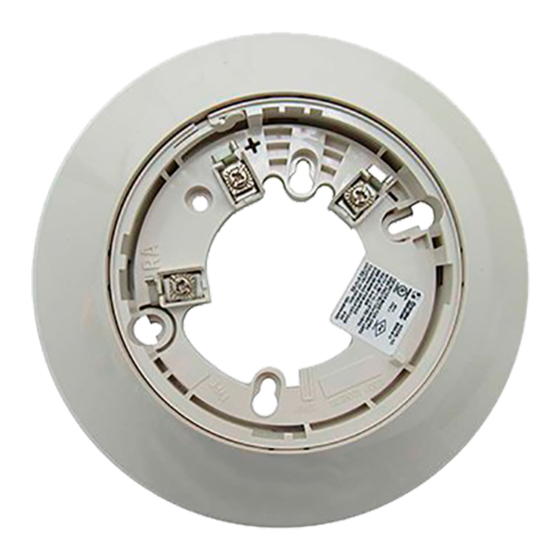
BASE TERMINALS
NO. FUNCTION
1
Power (–), Remote Annunciator (–)
2
Power (+)
3
Remote Annunciator (+)
FIGURE 1. TERMINAL LAYOUT
TERMINAL 2
TERMINAL 3
MOUNTING
This detector base mounts directly to 4-inch square (with and without plaster
rings), 4-inch octagon, 3
1
/
-inch octagon, and single gang junction boxes. To
2
mount, remove the decorative ring by turning it in either direction to unhook
the snaps, then separate the ring from the base. Install the base on the box
using the screws supplied with the junction box and the appropriate mounting
slots in the base.
Place the decorative trim ring on the base and rotate it in either direction until
it snaps into place. (See Figure 2.)
6.1 inches (155 mm)
0.76 inches (19 mm)
Refer to applicable sensor Operating Temperature Range using the Base/Sensor Cross Reference Chart at systemsensor.com.
15 to 32 VDC
170 µA
TERMINAL 1
C0127-07
6581 Kitimat Road, Unit 6, Mississauga, Ontario L5N-3T5
FIGURE 2. MOUNTING DETECTOR TO BOX
INSTALLATION AND WIRING GUIDELINES (SEE FIGURE 3)
All wiring must be installed in compliance with all applicable local codes
and any special requirements of the authority having jurisdiction. Proper wire
gauges should be used. The conductors used to connect smoke detectors to
control panels and accessory devices should be color-coded to reduce the like-
lihood of wiring errors. Improper connections can prevent a system from re-
sponding properly in the event of a fire.
For signal wiring (the wiring between interconnected detectors), it is recom-
mended that the wire be no smaller than 18 AWG (0.823 mm²). Wire sizes up
to 12 AWG (3.31 mm²) may be used with the base.
Make electrical connections by stripping about
from the end of the wire (use strip gauge molded in base). Then slide the wire
under the clamping plate and tighten the clamping plate screw. Do not loop
the wire under the clamping plate. (See Figure 4.)
Check the zone wiring of all bases in the system before installing the detec-
tors. This includes checking the wiring for continuity, correct polarity, ground
fault testing and performing a dielectric test.
The base includes an area for recording the zone, address, and type of detec-
tor being installed. This information is useful for setting the detector head
address and for verification of the detector type required for that location.
Once all detector bases have been wired and mounted, and the loop wiring
has been checked, the detector heads may be installed in the bases.
1
800/736-7672, FAX: 905-812-0771
www.systemsensor.ca
SNAP ON
DECORATIVE
RING
SCREWS
(NOT SUPPLIED)
DETECTOR
BASE
BOX
(NOT SUPPLIED)
C2036-01
3
/
inch (10 mm) of insulation
8
I56-9127-001
11/17/2017
Advertisement

Related Manuals for System Sensor B300A-6


Summary of Contents for System Sensor B300A-6
- Page 1 GENERAL DESCRIPTION The B300A-6 and B300A-6-IV are plug-in detector bases intended for use in an intelligent system, with screw terminals provided for power (+ and –), and remote annunciator connections. Communication takes place over the power DETECTOR lines (+ and –).
- Page 2 Please refer to insert for the Limitations of Fire Alarm Systems THREE-YEAR LIMITED WARRANTY System Sensor warrants its enclosed smoke detector base to be free from defects in ma- Repair Department, RA #__________, 6581 Kitimat Road, Unit 6, Mississauga, Ontario terials and workmanship under normal use and service for a period of three years from L5N-3T5.
Need help?
Do you have a question about the B300A-6 and is the answer not in the manual?
Questions and answers