Advertisement
Quick Links
DESCRIPTION
Demonstration circuit 2317A is a 100V monolithic DC/
DC step-down regulator featuring the
demo board is designed for a 5V/2.3A output from a 5V
to 100V input at 400kHz switching frequency. The wide
input range makes it suitable for automotive, industrial,
medical instrument, and telecom applications. This buck
regulator has a peak efficiency of 93.5% at 12V
at 48V
and 81.5% at 100V
IN
The LTC7103 is a compact, high efficiency synchronous
monolithic step-down switching regulator with fast cur-
rent programming. The power switches, compensation
network and other necessary circuits are inside of the
LTC7103 to minimize external components and simplify
design. The LTC7103 has wide operating range from 4.4V
to 105V. A 40ns minimum on-time, together with 100%
maximum duty cycle allow practical use at any output volt-
age between 1V and V
. The switching frequency can be
IN
programmed either via an oscillator resistor or an external
clock over a 200kHz to 2MHz range. Additional features
include a fast and accurate output current programming
and monitoring, and ultralow EMI/EMC emissions.
The demo board has an EMI filter installed. The EMI
performance of the board (with EMI filter) is shown in
Figure 2. The figure shows that the circuit passes the
PERFORMANCE SUMMARY
SYMBOL
PARAMETER
V
Input Supply Range
IN
V
Output Voltage
OUT
I
Output Current Range, Continuous
OUT
f
Switching (Clock) Frequency
SW
V
Output Ripple
OUTP-P
P
/PIN
Efficiency
OUT
Approximate Size
105V, 2.3A Low EMI Synchronous
LTC
7103. The
®
, 88.3%
IN
(see Figure 3).
IN
Specifications are at T
CONDITIONS
Free Air
V
= 100V, V
IN
OUT
V
= 12V, I
IN
OUT
V
= 48V, I
IN
OUT
Component Area x Top Component Height
Step-Down Regulator
CISPR 25 radiated emission test with a wide margin. To
achieve EMI/EMC performance as shown in Figure 2, the
input EMI filter is required and the input voltage should
be applied at +VIN_EMI turret pin.
The demo board provides current monitor and output
clock signal to interface with an external application cir-
cuit. User selectable mode selection (JP1) is provided and
Burst Mode
operation position is selected by default.
®
Burst Mode operation increases light load efficiency while
pulse-skipping mode allows constant-frequency operation
to a lighter load. This demo board allows phase-locked
loop (PLL) synchronization to an external clock by select-
ing SYNC mode on JP1 and by providing a clock signal
on CLKIN turret.
The LTC7103 data sheet gives a complete description of
the part, operation and application information. The data
sheet must be read in conjunction with this demo manual
for DC2317A. The LTC7103 is assembled in the 36 (26)
lead QFN package. Proper board layout is essential for
maximum thermal and electrical performance. See the
data sheet sections for details.
Design files for this circuit board are available at
http://www.linear.com/demo/DC2317A
L, LT, LTC, LTM, Linear Technology, the Linear logo and Burst Mode are registered trademarks
of Analog Devices, Inc. All other trademarks are the property of their respective owners.
= 25°C
A
= 5V, I
= 2.3A (20MHz BW)
OUT
= 1A
= 1A
DEMO MANUAL
DC2317A
LTC7103
MIN
TYP
MAX
5
100
5
0
2.3
400
50
92.6
88.1
1.0 × 0.7 × 0.3
UNITS
V
V
A
kHz
mV
P-P
%
%
Inches
dc2317af
1
Advertisement

Related Manuals for Linear Technology LTC7103


Summary of Contents for Linear Technology LTC7103
- Page 1 Figure 2. The figure shows that the circuit passes the L, LT, LTC, LTM, Linear Technology, the Linear logo and Burst Mode are registered trademarks of Analog Devices, Inc. All other trademarks are the property of their respective owners. PERFORMANCE SUMMARY Specifications are at T = 25°C...
-
Page 2: Quick Start Procedure
DEMO MANUAL DC2317A QUICK START PROCEDURE 5. Check for the proper output voltage using a voltmeter. Refer to Figure 1 for proper measurement equipment Output voltage should be within 5.0V ± 0.1V. setup and follow the procedure below. Note: If there is no output, temporarily disconnect the Note: When measuring the output voltage ripple, care load to make sure that the load is not set too high. - Page 3 DEMO MANUAL DC2317A QUICK START PROCEDURE VERTICAL POLARIZATION CLASS 5 PEAK LIMIT LTC7103 1000 FREQUENCY (MHz) dc2017a F02a HORIZONTAL POLARIZATION CLASS 5 PEAK LIMIT LTC7103 1000 FREQUENCY (MHz) dc2017a F02b Figure 2. EMI Performance in CISPR 25 Radiated Emission Test (48V...
- Page 4 DEMO MANUAL DC2317A QUICK START PROCEDURE Figure 3. Efficiency at Various Input Voltages (Conditions: Burst Mode Operation) Figure 4. Efficiency at Various Input Voltages (Conditions: Pulse-Skipping Mode) dc2317af...
- Page 5 DEMO MANUAL DC2317A QUICK START PROCEDURE Figure 5. Output Ripple at 100V , 5V and 2.3A (50mV, 500ns/DIV, 20MHz Bandwidth) Figure 6. Transient Response Waveform at 48V , 5V and 1.1A to 2.3A to 1.1A (1A, 200mV, 50μs/DIV, 20MHz Bandwidth) dc2317af...
- Page 6 DEMO MANUAL DC2317A QUICK START PROCEDURE Conditions: 12V , 5V at 2.3A Conditions: 24V , 5V at 2.3A Conditions: 48V , 5V at 2.3A Conditions: 100V , 5V at 2.3A Figure 7. Thermal Plots (without Forced Air) dc2317af...
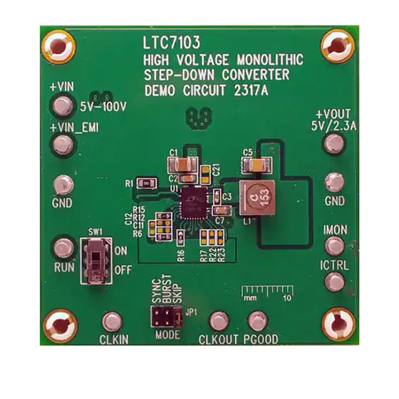
- Page 7 DEMO MANUAL DC2317A QUICK START PROCEDURE Figure 8. Board Photo dc2317af...
-
Page 8: Parts List
DEMO MANUAL DC2317A PARTS LIST ITEM REFERENCE PART DESCRIPTION MANUFACTURER/PART NUMBER Required Circuit Components C1, C13, C16 CAP , X7R 4.7µF, 100V, 20% 1210 MURATA, GRM32ER72A475KE14 CAP , X7R, 0.1µF, 100V, 10%, 0805 MURATA, GCM21BR72A104KA37L CAP , X7R, 0.1µF, 25V, 10%, 0603 MURATA, GRM188R71E104KA01D CAP , X6S, 100µF, 6.3V, 20%, 1210 MURATA, GRM32EC80J107ME20L... -
Page 9: Schematic Diagram
Information furnished by Linear Technology Corporation is believed to be accurate and reliable. However, no responsibility is assumed for its use. Linear Technology Corporation makes no representa- tion that the interconnection of its circuits as described herein will not infringe on existing patent rights. - Page 10 Linear Technology Corporation (LTC) provides the enclosed product(s) under the following AS IS conditions: This demonstration board (DEMO BOARD) kit being sold or provided by Linear Technology is intended for use for ENGINEERING DEVELOPMENT OR EVALUATION PURPOSES ONLY and is not provided by LTC for commercial use. As such, the DEMO BOARD herein may not be complete in terms of required design-, marketing-, and/or manufacturing-related protective considerations, including but not limited to product safety measures typically found in finished commercial goods.
Need help?
Do you have a question about the LTC7103 and is the answer not in the manual?
Questions and answers