Advertisement
Quick Links
DESCRIPTION
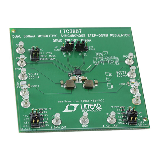
Demonstration circuit DC1596 is a dual output regulator
consisting of two constant-frequency step-down convert-
ers, based on the
LTC
®
synchronous buck regulator. The DC1596 has an input
voltage range of 4.5V to 15V, with each regulator capable of
delivering up to 600mA of output current. The DC1596 can
operate in either Burst Mode
mode. In shutdown, the DC1596 quiescent current is less
than 1µA. The DC1596 is a very efficient circuit attaining
up to 90%. The DC1596 uses the LTC3607's16-lead QFN
PERFORMANCE SUMMARY
PARAMETER
Minimum Input Voltage
Maximum Input Voltage
Run
Output Voltage V
Regulation
OUT1
Typical Output Ripple V
OUT1
Output Voltage V
Regulation
OUT2
Typical Output Ripple V
OUT2
Mode Setting
Burst Mode Operation Output Current Thresholds
Pulse-Skipping Operation Output Current
Thresholds
Switching Frequency
Synchronous Step-Down Regulator
3607
monolithic dual channel
operation or pulse-skipping
®
Specifications are at T
CONDITIONS
RUN Pin = GND
RUN Pin = V
IN
V
= 4.5V to 15V, I
IN1
V
= 12V, I
IN1
OUT1
V
= 4.5V to 15V, I
IN2
V
= 12V, I
IN2
OUT2
Mode Pin Floating
Mode Pin Grounded
Channel 1: PV
Channel 2: PV
Channel 1: PV
Channel 2: PV
DEMO MANUAL DC1596A
Dual 600mA 15V Monolithic
package, which has an exposed pad on the bottom side
of the IC for better thermal performance. These features,
plus a set operating frequency range of 2.25MHz, make
the DC1596 demo board an ideal circuit for industrial or
distributed power applications.
Design files for this circuit board are available at
http://www.linear.com/demo
L, LT, LTC, LTM, Linear Technology, the Linear logo and Burst Mode are registered trademarks
of Linear Technology Corporation. All other trademarks are the property of their respective
owners.
= 25°C
A
= 0A to 600mA
OUT1
= 600mA (20MHz BW)
= 0A to 600mA
OUT2
= 600mA (20MHz BW)
= 12V, V
= 1.8V
IN1
OUT1
= 12V, V
= 3.3V
IN2
OUT2
= 12V, V
= 1.8V
IN1
OUT1
= 12V, V
= 3.3V
IN2
OUT2
LTC3607EUD
VALUE
4.5V
15V
Shutdown
Operating
1.2V ±4% (1.152V-1.148V)
1.5V ±4% (1.44V-1.56V)
1.8V ±4% (1.728V-1.872V)
<20mV
P-P
2.5V ±4% (2.425V-2.6V)
3.3V ±4% (3.168V-3.432V)
5V ±4% (4.8V-5.2V)
<20mV
P-P
Burst Mode Operation
Pulse-Skipping
I
< 480mA
OUT1
I
< 360mA
OUT2
I
< 330mA
OUT1
I
< 240mA
OUT2
2.25MHz ±20%
dc1596afa
1
Advertisement

Subscribe to Our Youtube Channel
Related Manuals for Linear Technology DC1596A


Summary of Contents for Linear Technology DC1596A
- Page 1 In shutdown, the DC1596 quiescent current is less L, LT, LTC, LTM, Linear Technology, the Linear logo and Burst Mode are registered trademarks than 1µA. The DC1596 is a very efficient circuit attaining of Linear Technology Corporation. All other trademarks are the property of their respective up to 90%.
- Page 2 DEMO MANUAL DC1596A QUICK START PROCEDURE The DC1596 is easy to set up to evaluate the performance 5. Set the load current of both outputs to 600mA and the of the LTC3607. For a proper measurement equipment input voltages to 12V, and then measure each output...
-
Page 3: Quick Start Procedure
DEMO MANUAL DC1596A QUICK START PROCEDURE Figure 1. Proper Measurement Equipment Setup Figure 2. Measuring Input or Output Ripple dc1596afa... - Page 4 DEMO MANUAL DC1596A QUICK START PROCEDURE 10V/DIV 100mV/DIV OUT1 AC-COUPLED 20mV/DIV AC VOLTAGE 200mA/DIV 10V/DIV OUT2 20mV/DIV AC VOLTAGE 200ns/DIV DC1596A F03 20µs/DIV DC1596A F04 = 12V IN1,2 = 12V = 1.8V AT I = 600mA OUT1 OUT1 = 1.2V OUT1 = 3.3V AT I...
- Page 5 DEMO MANUAL DC1596A QUICK START PROCEDURE 100mV/DIV 100mV/DIV AC-COUPLED AC-COUPLED 200mA/DIV 200mA/DIV 20µs/DIV DC1596A F08 20µs/DIV DC1596A F07 = 12V = 12V = 3.3V = 2.5V OUT2 OUT2 400mA LOAD STEP (200mA TO 600mA) 400mA LOAD STEP (200mA TO 600mA) PULSE-SKIPPING MODE, f = 2.25MHz...
-
Page 6: Parts List
DEMO MANUAL DC1596A PARTS LIST ITEM REFERENCE PART DESCRIPTION MANUFACTURER/PART NUMBER Required Circuit Components CFFW1, CFFW2 CAP., NPO, 22pF, 25V, 5%, 0402 AVX, 04025A220JAT2A CIN1BYP, CIN2BYP CAP., X7R, 0.1µF, 16V, 10%, 0603 AVX, 0603YC104KAT2A COUT1, COUT2 CAP., X5R, 10µF, 6.3V, 10%, 0805... -
Page 7: Schematic Diagram
Information furnished by Linear Technology Corporation is believed to be accurate and reliable. However, no responsibility is assumed for its use. Linear Technology Corporation makes no representa- tion that the interconnection of its circuits as described herein will not infringe on existing patent rights. - Page 8 Linear Technology Corporation (LTC) provides the enclosed product(s) under the following AS IS conditions: This demonstration board (DEMO BOARD) kit being sold or provided by Linear Technology is intended for use for ENGINEERING DEVELOPMENT OR EVALUATION PURPOSES ONLY and is not provided by LTC for commercial use. As such, the DEMO BOARD herein may not be complete in terms of required design-, marketing-, and/or manufacturing-related protective considerations, including but not limited to product safety measures typically found in finished commercial goods.
Need help?
Do you have a question about the DC1596A and is the answer not in the manual?
Questions and answers