Table of Contents
Advertisement
Quick Links
QUICK START GUIDE FOR DEMONSTRATION CIRCUIT 824
WARNING: The LEDs on this demo board produce very bright light. Do not look directly at LEDs when power is
applied. Serious eye damage may occur.
DESCRIPTION
Demonstration circuit 824 is a multi-display LED
controller featuring the LTC3208.
The LTC3208 is a highly integrated multi-display
LED controller. This device contains a high effi-
ciency, low noise charge pump to provide power
for a MAIN, SUB, and auxiliary (AUX) white LED
displays, an RGB color display, and a camera
(CAM) display with flash capabilities. The four aux-
iliary LEDs may be individually configured to the
MAIN, SUB, CAM, or AUX display. The LTC3208
requires only four small ceramic capacitors plus
one resistor to form a complete 5-panel LED
power supply and current controller.
The maximum display currents are set with a sin-
gle 24.3K ohm resistor. Current for each LED is
controlled with a precision internal current source.
Dimming and ON/OFF control for all displays are
achieved via a 2-wire I
SUB panel may be disabled via the ENRGB/S pin.
QUICK START PROCEDURE
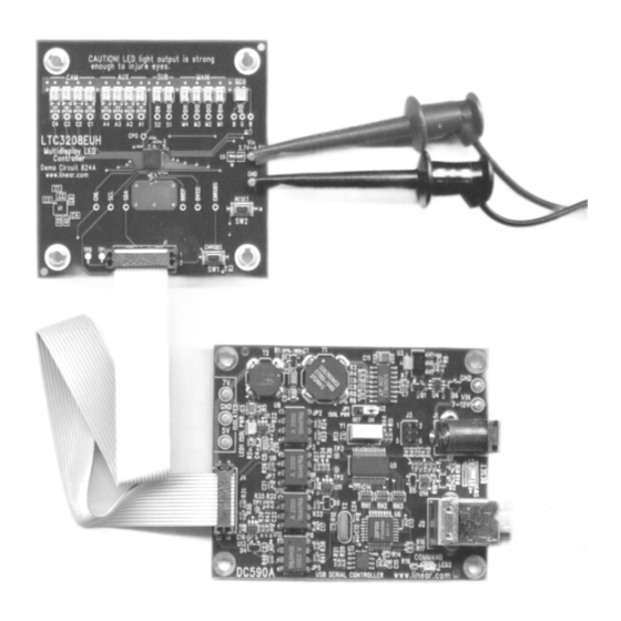
Demonstration circuit 824 is easy to setup to evalu-
ate the performance of the LTC3208. Refer to Figure
1 and Figure 2 for proper measurement equipment
setup and follow the procedure below.
1. Refer to the DC590 Quick Start guide for DC590
and QuickEval TM setup and software installation
details.
2. Make sure the USB cable is connected between
the computer and the DC590 controller board.
3. Connect DC824 to the DC590 USB Serial Con-
troller using the supplied 14-conductor ribbon
cable as shown in Figure 1.
2
C interface. The RGB or
MULTIDISPLAY LED CONTROLLER
256 dimming states exist for the MAIN and SUB
panels. 16 states are available for the RGB, CAM,
and AUX displays. The RGB LED may display up
to 4096 color combinations.
The LTC3208 charge pump optimizes efficiency
based on the voltage across the LED current
sources. The part powers up in 1X mode and will
automatically switch to boost mode whenever any
enabled LED current source begins to drop out.
The first dropout switches the part to 1.5X mode
and a subsequent dropout switches the part into
2X mode. The charge pump can also be pro-
grammed to 1.5X mode or 2X mode via the I
interface.
Design files for this circuit board are available. Call
the LTC factory.
, LTC and LT are registered trademarks of Linear Technology Corporation.
4. Attach a 2.9 – 4.5V power source to the Vin and
GND turrets of the DC824 demo circuit as shown
in Figure 2. This is the Vin power supply for the
LTC3208 (see application schematic). DC824 has
an extra 4.7uF de-coupling capacitor on Vin to
help accommodate long lead lengths. DC590
gets its power from the USB cable.
5. Run the QuickEval TM program. The program
detects the DC824 and displays the LTC3208
control window (shown in Figure 3).
LTC3208
2
C
1
Advertisement
Table of Contents

Related Manuals for Linear Technology 824


Summary of Contents for Linear Technology 824
- Page 1 LTC factory. Dimming and ON/OFF control for all displays are , LTC and LT are registered trademarks of Linear Technology Corporation. achieved via a 2-wire I C interface. The RGB or SUB panel may be disabled via the ENRGB/S pin.
- Page 2 QUICK START GUIDE FOR DEMONSTRATION CIRCUIT 824 MULTIDISPLAY LED CONTROLLER Figure 1. Proper Serial Interface Connection Figure 2. Proper Measurement and Equipment Setup...
- Page 3 QUICK START GUIDE FOR DEMONSTRATION CIRCUIT 824 MULTIDISPLAY LED CONTROLLER USING THE LTC3208 QUICKEVAL SOFTWARE The program provides brightness controls for the vertical scroll bar to increment by 10 hex LSBs. MAIN, SUB, CAM, AUX, and RGB LEDs. The The hex code is displayed in the box below each UPDATE ALL REG button updates all registers slider.
- Page 4 QUICK START GUIDE FOR DEMONSTRATION CIRCUIT 824 MULTIDISPLAY LED CONTROLLER colors that can be produced by the Nichia LEDS OFF Button – This button will turn off all NSCM315C RGB diode. the LEDs and will turn off and reset any active demo.
- Page 5 QUICK START GUIDE FOR DEMONSTRATION CIRCUIT 824 MULTIDISPLAY LED CONTROLLER Figure 3. LTC3208 Control Window...
- Page 6 QUICK START GUIDE FOR DEMONSTRATION CIRCUIT 824 MULTIDISPLAY LED CONTROLLER...
- Page 7 Mouser Electronics Authorized Distributor Click to View Pricing, Inventory, Delivery & Lifecycle Information: Analog Devices Inc. DC824A...
Need help?
Do you have a question about the 824 and is the answer not in the manual?
Questions and answers