Advertisement
Quick Links
DESCRIPTION
WARNING!
Do not look directly at operating LED.
This circuit produces light that can damage eyes.
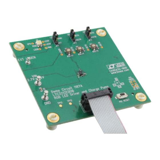
Demonstration circuit 1187 is an RGB LED Driver
and Charge Pump featuring the LTC3212.
The LTC3212 is a low noise charge pump capable
of driving three LEDs up to 25mA each. This de-
vice requires only one flying capacitor, two by-pass
capacitors, and one to three programming resis-
tors. Each LED may be turned on individually, in
combination with each other, or in white mode us-
PERFORMANCE SUMMARY
PARAMETER
Input Supply Range
I
Shutdown Current
VIN
I
Operating Current
VIN
I
LED
I
(WHITE MODE)
LEDG
I
(WHITE MODE)
LEDB
I
(WHITE MODE)
LEDR
I
Dropout Voltage (V
)
LED
ILED
Charge Pump Output Clamp Voltage
I
CPO
ing a single wire interface. White mode optimizes
the red, green, and blue current settings to provide
the best white color.
LED currents are regulated using internal low
dropout current sources. Automatic mode switch-
ing optimizes efficiency by switching modes only
when a dropout is detected. Refer to the LTC3212
datasheet for more information on this device.
Design files for this circuit board are available.
Call the LTC factory.
, LTC, LTM, and LT are registered trademarks of Linear Technology Corporation.
L
Other product names may be trademarks of the companies that manufacture the
products.
Specifications are at T
CONDITIONS
LEDEN = LOW
= 0mA, 1X Mode
I CPO
= 0mA, 2X Mode
I CPO
R
= 33.87KΩ (Not in White Mode)
ISET
R
= 58.87KΩ (Not in White Mode)
ISET
R
= 8.87KΩ (Not in White Mode)
ISET
R
= 33.87KΩ
ISETG
R
= 58.87KΩ
ISETG
R
= 8.87KΩ
ISETG
R
= 33.87KΩ
ISETG
R
= 58.87KΩ
ISETG
R
= 8.87KΩ
ISETG
R
= 33.87KΩ
ISETG
R
= 58.87KΩ
ISETG
R
= 8.87KΩ
ISETG
Mode Switching Threshold, I
LED
DEMO CIRCUIT 1187
QUICK START GUIDE
RGB LED Driver and
Charge Pump
= 25° C
A
MIN
2.7
= 15mA
0
LTC3212
LTC3212
TYP
MAX
UNITS
5.5
V
3
8
µA
0.4
mA
2.0
mA
5.24
mA
3.0
mA
20.0
mA
5.24
mA
3.0
mA
20.0
mA
3.93
mA
2.62
mA
15.0
mA
4.72
mA
2.71
mA
18.0
mA
150
mV
5.1
V
75
mA
1
Advertisement

Related Manuals for Linear Technology LTC3212


Summary of Contents for Linear Technology LTC3212
- Page 1 , LTC, LTM, and LT are registered trademarks of Linear Technology Corporation. tors. Each LED may be turned on individually, in Other product names may be trademarks of the companies that manufacture the products.
-
Page 2: Operating Principles
C board LEDG is set by the RSETG potentiometer, R4. The and drives the LTC3212 via a single wire interface. currents for LEDR and/or LEDB are also set by the The current in each LED output is set by adjusting RSETG potentiometer when in white mode and the resistance at the associated ISET pin. - Page 3 Observe that the LED illuminates pink. greenish blue. 19. Select the White Mode option button on the 16. Move the ISETB jumper from RSETB to LTC3212 control window. Observe that the RGB RSETG and observe the RGB LED color illuminates a whitish color. change.
- Page 4 Figure 1. Proper Measurement Equipment Setup Figure 2. Measuring Input or Output Ripple LTC3212 SOFTWARE CONTROL WINDOW The LTC3212 software control window consists of select white mode. White mode turns on the three 7 LED Enable Mode option buttons, which allow LEDs at an optimal intensity to display white light.
- Page 5 LTC3212. The Update button updates web site for the LTC3212, providing an internet the microcontroller with the proper timing informa- connection is available. tion and updates the LTC3212 to match the se- LED ENABLE SETTINGS lected LED Enable mode option button. The Up- PULSES...
- Page 6 LTC3212...
- Page 7 LTC3212...
- Page 8 Mouser Electronics Authorized Distributor Click to View Pricing, Inventory, Delivery & Lifecycle Information: Analog Devices Inc. DC1187A...
Need help?
Do you have a question about the LTC3212 and is the answer not in the manual?
Questions and answers