Advertisement
Designing, Manufacturing and Supplying WB Series Electric Isolated Transducer and
Digital Electrical Transducer since 1989
USER MANUAL
WBI417S41 TRUE RMS SENSING
AC current transducer
www.weiboelectronic.cn
wbwm@wbdz.cn
Tel: 86 0816 2971265
Fax: 86 0816 2281934
ISO9001/ ISO14000/ ISO18000 /Certified Company
Advertisement
Table of Contents

Subscribe to Our Youtube Channel
Related Manuals for Mianyang Weibo Electronic WBI417S41


Summary of Contents for Mianyang Weibo Electronic WBI417S41
- Page 1 Designing, Manufacturing and Supplying WB Series Electric Isolated Transducer and Digital Electrical Transducer since 1989 USER MANUAL WBI417S41 TRUE RMS SENSING AC current transducer www.weiboelectronic.cn wbwm@wbdz.cn Tel: 86 0816 2971265 Fax: 86 0816 2281934 ISO9001/ ISO14000/ ISO18000 /Certified Company...
- Page 2 WBI417S41 TRUE RMS SENSING AC current transducer Safety claim The information in the safety claim of the equipment documentation is intended to ensure that equipment is properly installed in order to maintain it in a condition. It is assumed that everyone who will be associated with the equipment will be familiar with the contents of that safety section, or this safety guide.
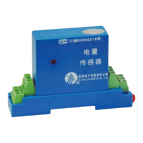
- Page 3 Product Description and Application WBI417S41 converts AC input current into a load independent output signal true RMS (0)4-20mA. It has adopted electromagnetic isolation principle for real time measurement of AC current from electric net or electric circuit. It is good application for measurement of distorted current waveform.
- Page 4 Key Technical Data: 1. Input: AC 0~0.5A; 0-1A; 0-2A; 0-3A; 0-5A; 0-8A; ( Optional) 2. Output: TRUE RMS 0-20mA or 4-20mA; 3. Accuracy class: 0.2 4. Frequency range: 25Hz~1kHz 5. Linear Range: 0~120% of nominal input 6. Responding Time: 300ms 7.
- Page 5 3. The auxiliary power requires isolation voltage≥2000VAC, DC current output ripple<10mV. 4. Multiple transducers can share with one set auxiliary power together., and the wire shared between the transducers and power should be short. It's better to connect each transducer to the auxiliary power individually.
- Page 6 (5) Using output monitoring meter V2 to measuring the output voltage Uo of the transducer, the basic introduced errorγof the transducer should be calculated as: γ= (Uo-Iz×250Ω)/[(20mA-4mA)×250Ω]×100 (6) Repeating step (4) (5), if calculated absolute value is less than the given accuracy value of the transducer;...
Need help?
Do you have a question about the WBI417S41 and is the answer not in the manual?
Questions and answers