Table of Contents
Advertisement
Quick Links
Advertisement
Table of Contents

Related Manuals for QDI LEGEND-V


Summary of Contents for QDI LEGEND-V
- Page 1 ® PENTIUM Legend - V...
- Page 2 Residential, commercial and light industry European Representative: QDI COMPUTER ( UK ) LTD QDI COMPUTER ( SCANDINAVIA ) A/S QDI SYSTEM HANDEL GMBHQDI COMPUTER ( NETHERLANDS) B. V. QDI COMPUTER (FRANCE) SARL QDI COMPUTER HANDELS GMBH QDI COMPUTER (ESPANA) S.A.
- Page 3 Trade Name: QDI Computer ( U. S . A. ) Inc. Model Name: Legend -V Responsible Party: QDI Computer ( U. S. A.) Inc. Address: 41456 Christy Street Fremont, CA 94538 Telephone: (510) 668-4933 Facsimile: (510) 668-4966 Equipment Classification: FCC Class B Subassembly...
- Page 4 Notice The information in this document is subject to change in order to improve reliability, design, or function without prior notice and does not represent a commitment on the part of this company. In no event will we be liable for direct, indirect, special, incidental, or consequential damages arising out of the use or the possibility of such damages.
-
Page 6: Table Of Contents
CONTENTS SpeedEasy Quick Setup(English)---------------------------------------- 1 SpeadEasy Schnell-Installation(Deutsch)------------------------------ 3 Fácil Y Veloz Rápida Instalación(Español) --------------------------- 5 Facilité de vitesse Initialisation(Francais)----------------------------- 7 Setup Della Scheda Speedeasy(Italiano) ------------------------------- 9 SpeedEasy¿ìËÙ°²×°Ö¸ÄÏ(ÖÐÎÄ·±Ìå )---------------------------------- 11 SpeedEasy¿ìËÙ°²×°Ö¸ÄÏ(ÖÐÎļòÌå ) -------------------------------- 13 1. Introduction -------------------------------- -------------- 1-1 Overview ------------------------------------------------------------------ 1-1 Key Features-------------------------------------------------------------- 1-1 2. - Page 7 CONTENTS Load Setup Defaults ----------------------------------------------------- 3-2 Standard CMOS Setup -------------------------------------------------- 3-2 SpeedEasy CPU Setup -------------------------------------------------- 3-5 BIOS Features Setup ---------------------------------------------------- 3-6 Chipset Features Setup-------------------------------------------------- 3-8 Power Management Setup ---------------------------------------------- 3-11 PNP/PCI Configuration Setup ---------------------------------------- 3-14 Integrated Peripherals -------------------------------------------------- 3-16 System Monitor Setup --------------------------------------------------- 3-18 Supervisor/User Password Setting------------------------------------- 3-19 IDE HDD Auto Detection ---------------------------------------------- 3-20 Power-on Boot------------------------------------------------------------ 3-22...
-
Page 9: Speedeasy Quick Setup(English)
Legend - V SpeedEasy Quick Setup Procedures : ® Insert the Pentium II correctly. Plug in other configurations and restore the system. Press <Del> key and switch on power to the system to enter BIOS Setup. Enter “SpeedEasy CPU Setup” menu to set up CPU speed. Note: If you do not set CPU speed, your system will run at ®... - Page 10 SpeedEasy Type Introduction Select <SpeedEasy CPU Setup> item from the main menu and enter the sub- menu: ROM PCI/ISA BIOS (2A69JQ1D) SpeedEasy CPU SETUP QDI Innovative Technology CPU Model : Pentium(R)II Warning: Be sure your selection Speed Mode : SpeedEasy is right .CPU over speed will...
- Page 11 Legend - Serie Schnell-Installation durch SpeadEasy Vorgehensweise der Installation: 1. Legen Sie die Pentium® II im Slot 1 mit Hilfe der mitgelieferten Halterung. Vervollstä n digen Sie das System mit den weiteren erforderlichen Computerkomponenten Drü c ken Sie die “ T aste < Entf > und schalten Sie das System an um in das BIOS-setup zu gelangen.
- Page 12 Installationmenus ” einstellen. Warnung: Bitte setzen Sie die Taktfrequenz der CPU nicht höher als die tatsächliche freigegebene Taktfrequenz, ansonten kann QDI für rechtliche Anspruche nicht herangezogen werden. Achtung : Sollte sich lhr System wegen falscher CPU Einstellung nicht starten lassen, drüken, Sie die Taste <Del> und gleichzeitig die Power On Taste.
- Page 13 Legend - V SpeedEasy Instalación rápida Procedimiento: 1. Introduzca correctamente el Pentium® I I. 2. Finalize el proceso de ensamblaje de su equipo. 3. Presione la tecla <Supr> y encienda el sistema, paraentrar en BIOS. 4. Entre al menu “ S peedEasy CPU setup” para establecer la velocidad de su CPU.
- Page 14 Menu del SpeedEasy CPU Seleccione el item <SpeedEasy CPU setup> desde el menu principal , y entre en el submenu: ROM PCI/ISA BIOS (2A69JQ1D) SpeedEasy CPU SETUP QDI Innovative Technology CPU Model : Pentium(R)II Warning: Be sure your selection Speed Mode : SpeedEasy is right .CPU over speed will...
-
Page 15: Facilité De Vitesse Initialisation(Francais)
Legend - V Facilité de vitesse Initialisation Procédure: 1. Insérez le Pentium® II correctement. 2. Connectez les autres configurations et restaurez le système. 3. Appuyez sur la touche <Del> et mettez le système sous tension pour entrer dans l’ i nitialisation BIOS. 4. - Page 16 Menu d’ i nitialisation de “ S peedEasy” dans l’ u nité centrale. Sélectionnez la rubrique <SpeedEasy CPU Setup> dans le menu principal et entrez le sous-menu: ROM PCI/ISA BIOS (2A69JQ1D) SpeedEasy CPU SETUP QDI Innovative Technology CPU Model : Pentium(R)II Warning: Be sure your selection Speed Mode : SpeedEasy is right .CPU over speed will...
-
Page 17: Setup Della Scheda Speedeasy(Italiano)
Legend - V SETUP DELLA SCHEDA SPEEDEASY Procedura di installazione: 1. Inserite il microprocessore Pentium® I I come da istruzioni. 2. Modificate la configurazione del computer e ripristinate il sistema. 3. Premete il tasto <Del> e accendete il computer per entrare nel setup BIOS. - Page 18 Menu del Setup del Microprocessore SpeedEasy Selezionare <SpeedEasy CPU Setup> dal menu principale ed entrare nel seguente sottomenu: ROM PCI/ISA BIOS (2A69JQ1D) SpeedEasy CPU SETUP QDI Innovative Technology CPU Model : Pentium(R)II Warning: Be sure your selection Speed Mode : SpeedEasy is right .CPU over speed will...
- Page 19 Legend - V ¿ ì Ë Ù ° ² × ° Ö ¸ Ä Ï SpeedEasy ³ÌÐò£º ¡ ¢ Õ ý È · µ Ø ² å È ë entium® II¡ £ ¡ ¢ ² å È ë Æ ä Ë û Å ä Ö Ã £ ¬ × é × ° ³ É Í ê Õ û µ Ä Ï µ Í ³ ¡ £ ¡...
- Page 20 Ï î Ä ¿ £ ¬ È » á á ½ ø È ë ´ Î Ï î Ä ¿ µ ¥ £ º < SpeedEasy CPU Setup> ROM PCI/ISA BIOS (2A69JQ1D) SpeedEasy CPU SETUP QDI Innovative Technology CPU Model : Pentium(R)II Warning: Be sure your selection...
- Page 21 Legend - V ¿ ì Ë Ù ° ² × ° Ö ¸ Ä Ï SpeedEasy ³ÌÐò£º ¡ ¢ Õ ý È · µ Ø ² å È ë ¡ £ Pentium ® II ¡ ¢ ² å È ë Æ ä Ë û Å ä Ö Ã £ ¬ × é × ° ³ É Í ê Õ û µ Ä Î ¢ » ú Ï µ Í ³ ¡ £ ¡...
- Page 22 Ï î Ä ¿ £ ¬ È » á á ½ ø È ë ´ Î Ï î Ä ¿ µ ¥ £ º < SpeedEasy CPU Setup> ROM PCI/ISA BIOS (2A69JQ1D) SpeedEasy CPU SETUP QDI Innovative Technology CPU Model : Pentium(R)II Warning: Be sure your selection...
-
Page 23: Introduction
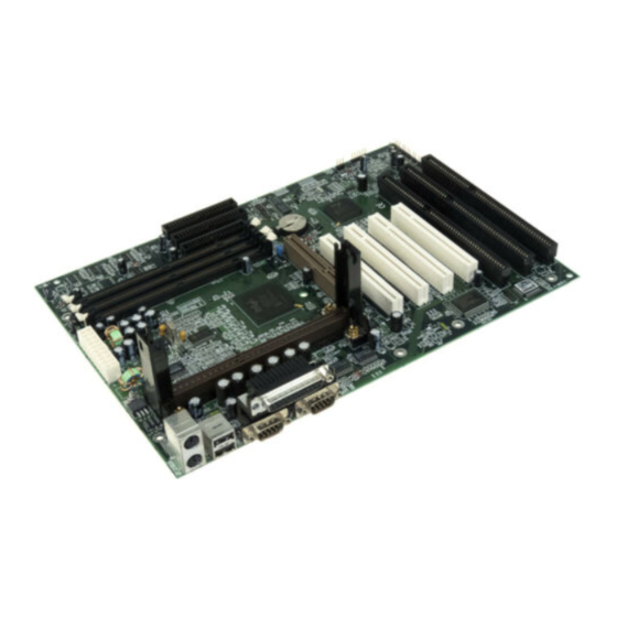
Chapter 1 Chapter 1 Introduction Overview Legend-V green mainboard provides a highly integrated solution for fully compatible, high performance PC/ATX platforms, and supports ® Pentium II processors, flexible main memory size can be installed from 8MB up to 384MB SDRAM or 8MB up to 768MB EDO DIMM, so as to ®... - Page 24 Intorduction • Supports memory ECC (Error Checking and Correction) function. On-board IDE • Supports two PCI PIO and bus Master IDE ports. • supports up to Mode 4 Timing • Supports 2 Fast IDE interfaces for up to 4 IDE devices including IDE hard disks and CD ROMs •...
- Page 25 Chapter 1 Advanced Feature • On board LM78 support system monitoring(monitor system voltages, chassis intrusion and FAN speed) (Optional) • Supports LDCM(LanDesk Client Manager) software (Optional) • On board PS/2 mouse and PS/2 keyboard socket • Two USB ports • On board switching voltage regulator with VID (support1.3V to 3.5V) •...
- Page 26 Intorduction -- This page is intentionally left blank -- 1 - 4...
-
Page 27: Connector Configuration
Chapter 2 Chapter 2 Connector Configuration This section lists all connector pin assignment and port description on the main-board. The situations of the connectors and ports are illustrated in the following figures. Before inserting these connectors, please pay attention to the directions. Power/Sleep LED Connector (PWRLED) PIN NUMBER FUNCTION... -
Page 28: Hard Disk Led Connector
Connector Configuration seconds before the system power down. For details, please refer to Page 3- Hard Disk LED Connector(HD.LED) PIN NUMBER FUNCTION LED ANODE LED CATHODE Speaker connector(SPEAKER) PIN NUMBER FUNCTION SPKDATA (for speaker) VCC (for speaker) Turbo LED Connector (TB. LED) PIN NUMBER FUNCTION LED ANODE... -
Page 29: Hardware Green Connector
Chapter 2 CLOSE ONCE RESET THE SYSTEM OPEN NORMAL Hardware Green Connector (SLEEP) SETTING FUNCTION CLOSE ONCE HARDWARE GREEN OPEN NORMAL Infrared Header(INFRARED) PIN NUMBER FUNCTION IRRX IRTX Controlled Fan Connector(CPUFAN,BAKFAN) PIN NAME FUNCTION FAN NEGA. 2 - 3... -
Page 30: Wake-Up On Lan
Connector Configuration FAN POSI. FAN SPEED Note: These two fans are set as “ON “ as default. Standard Fan Connector (CHSFAN) PIN NAME FUNCTION FAN NEGA. FAN POSI. FAN SPEED Wake-Up ON LAN (WOL2) PIN NUMBER FUNCTION +5V Standby Signal for waking up Note: This header is to be connected to a LAN adapter for wake-up on LAN. -
Page 31: Memory Configuration
Chapter 2 IDE1 Primary IDE Port IDE2 Secondary IDE Port FLOPPY Floppy Drive Port PRINTER Parallel Port UART1 COM1/COM2/COM3/COM4 UART2 COM2/COM3/COM4/COM1 USB1 First USB Port USB2 Second USB Port Accelerate graphics port Figure 2-1 Illustration of All Connectors on Board Memory Configuration 2 - 5... -
Page 32: Clear Cmos
Connector Configuration The Legend-V mainboard supports up to three 168 pin 3.3V un-buffered DIMM, provides a flexible size from 8MB up to 384MB SDRAM memory or from 8MB up to 768MB EDO memory. The following set of rules allows for optimum configurations. -
Page 33: Award Bios Description
Chapter 3 Chapter 3 AWARD BIOS Description Entering Setup Power on the computer, when the following message appears briefly at the bottom of the screen during the POST (Power On Self Test), press <Del> key or simultaneously press <Ctrl> + <Alt> + <Esc> keys. Press <Del>... -
Page 34: Load Setup Defaults
AWARD BIOS Description Load Setup Defaults The Setup Defaults is common and efficient setting. Standard CMOS Setup Use the arrow keys to highlight the item, then use the < PgUp> or <PgDn> keys to select the value you want in each item. ROM PCI/ISA BIOS(2A69JQ1D) STANDARD CMOS SETUP AWARD SOFTWARE, INC... - Page 35 Chapter 3 CYLS number of cylinders HEAD number of heads PRECOMP write precom LANDZ landing zone SECTOR number of sectors MODE HDD access mode Video You have two ways to boot up the system: When VGA is used as primary and monochrome is used as secondary, the selection of the video type is “EGA/VGA”...
- Page 36 AWARD BIOS Description Memory The category is display-only which is determined by POST (Power On Self Test) of the BIOS. Base Memory The POST of the BIOS will determine the amount of base (or conventional) memory installed in the system. Extended Memory The BIOS determines that how much extended memory is presented during the POST.
-
Page 37: Speedeasy Cpu Setup
Chapter 3 SpeedEasy CPU Setup ROM PCI/ISA BIOS(2A69JQ1D) SpeedEasy CPU SETUP QDI Innovative Techology CPU Model : Pentium( R ) II Speed Model : SpeedEasy CPU Speed : 233MH Warning : Be sure your selection is right. CPU over speed will be dangerous. -
Page 38: Bios Features Setup
AWARD BIOS Description BIOS Features Setup ROM PCI/ISA BIOS (2A69JQ1D) BIOS FEATURES SETUP AWARD SOFTWARE, INC. Virus Warning : Disabled Video BIOS Shadow Enabled C8000 ~ CBFFF Shadow : Disabled Pentium(R)II L1 Cache : Enabled CC000 ~ CFFFF Shadow : Disabled Pentium(R)II L2 Cache : Enabled D0000 ~ D3FFF Shadow : Disabled... - Page 39 Chapter 3 On Self Test some check items during POST to speed up POST after you power on the computer. Disabled Normal POST. • Boot Sequence A,C,SCSI, ... You can choose any search sequence for bootup. C, CDROM,A • Swap Floppy Enabled It will exchange the assignment of A&B floppy drives.
-
Page 40: Chipset Features Setup
AWARD BIOS Description Chipset Features Setup ROM PCI/ISA BIOS (2A69JQ1D) CHIPSET FEATURES SETUP AWARD SOFTWARE, INC. Auto Configuration : Enabled SDRAM CAS latency Time DRAM Speed Selection : 60ns MA Wait State : Slow EDO RAS # TO CAS# Delay EDO RAS # Precharge Time EDO DRAM Read Burst : X333... - Page 41 Chapter 3 Selection as 50ns, otherwise you have to select 60ns. 60ns • MA Wait State One additional wait state is inserted before the Slow assertion of the first MA and CAS#/RAS# during DRAM read or write leadoff cycles.This affects page hit, row miss and page miss cases. Without additional wait state.
-
Page 42: Power Management Setup
AWARD BIOS Description Transaction • AGP Aperture Size Set the effective size of the Graphics 4∼256 Aperture to be used in the particular PAC (MB) Configuration. • SDRAM RAS-To- Fast RAS-To-CAS Delay time=2 HCLK RAS-To-CAS Delay time=3 HCLK Slow CAS Delay •... - Page 43 Chapter 3 PM Control by APM :Yes IRQ [3-7, 9-15], NMI :Enabled Video Off Method +Blank Primary IDE 0 :Disabled V/H SYNC Video Off After :Standby Primary IDE 1 :Disabled MODEM Use IRQ Secondary IDE 0 :Disabled Secondary IDE 1 :Disabled Doze Mode :Disable...
- Page 44 AWARD BIOS Description cards to monitor. This function is enabled only for the VGA card DPMS supporting DPMS. Note: Green monitors detect the V/H-SYNC signals to turn off its electron gun . • Video Off After System BIOS will never turn off the screen. Screen off after system enters into Suspend mode.
-
Page 45: Pnp/Pci Configuration Setup
Chapter 3 you want to use Resume By Ring and Alarm. • IRQ [3-7, 9-15], Enabled Reload global timer. No influence to global timer. Disabled PNP/PCI Configuration Setup ROM PCI/ISA BIOS (2A69JQ1D) PNP/PCI CONFIGURATION SETUP AWARD SOFTWARE, INC. PNP OS Installed : No PCI IDE IRQ Map To: PCI-AUTO Resources Controlled By... - Page 46 AWARD BIOS Description IRQ-3 assigned to : Legacy ISA Used MEM base addr : N/A IRQ-4 assigned to : Legacy ISA IRQ-5 assigned to : PCI/ISA PnP IRQ-7 assigned to : Legacy ISA IRQ-9 assigned to : PCI/ISA PnP IRQ-10 assigned to : PCI/ISA PnP IRQ-11 assigned to : PCI/ISA PnP...
-
Page 47: Integrated Peripherals
Chapter 3 devices and determine the location of the PCI IDE device. PCI - SLOT4 ∼1 The BIOS will scan IRQ14 for primary IDE INT# and IRQ15 for secondary IDE INT# at the specified slot. The BIOS will not assign any IRQs even if PCI IDE card is found. - Page 48 AWARD BIOS Description IDE Secondary Master PIO : Auto IDE Secondary Slave PIO : Auto IDE Primary Master UDMA : Auto IDE Primary Slave UDMA : Auto IDE Secondary Master UDMA : Auto IDE Secondary Slave UDMA : Auto On-Chip Primary PCI IDE : Enabled On-Chip Secondary PCI IDE : Enabled...
-
Page 49: System Monitor Setup
Chapter 3 3E8/IRQ4, 2E8/IRQ3, Onboard serial port is disabled. Disabled, address interrupt number Auto automatically. • Serial Port 2 Mode Standard, Define Serial Port 2 as standard serial port This mode provides bi-directional Sharp IR, communication by transmitting and receiving infrared radiation. -
Page 50: Supervisor/User Password Setting
AWARD BIOS Description +3.3V Voltage : 3.32V VTT (+1.5V) Voltage : 1.53V` Voltage : 5.02V VCCVID (CPU) Voltage : 2.81V +12V Voltage : 11.96V -12V Voltage : -12.03V Voltage : -6.37 ↑↓→← : Select Item Chassis status : Closed ESC: QUIT F1 : Help PU/PD/+/- : Modify F5 : Old Values (Shift)F2: Color... -
Page 51: Ide Hdd Auto Detection
Chapter 3 To disable password, just press <Enter> when you are prompted to enter password. A message will confirm the password being disabled. Once the password is disabled, the system will boot and you can enter Setup freely. PASSWORD DISABLED If you select “... - Page 52 AWARD BIOS Description Primary Master: Select Primary Master Option ( N =Skip): N Option Size Cyls Heads Precomp Landzone Sectors Mode 2(Y) 1049 541 1050 65535 1049 NORMAL 65535 1049 LARGE Note: Some OSes (like SCO-UNIX) must use “NORMAL” for installation Figure-10 IDE HDD Auto Detection Menu 1.
-
Page 53: Power-On Boot
Chapter 3 If user sets his HDD to NORMAL mode,the maximum accessible HDD size will be 528 megabytes even though its physical size may be greater than that. LBA (Logical Block Addressing) mode A new HDD accessing method to overcome the 528 Megabyte bottleneck. The number of cylinders, heads and sectors shown in setup may not be the number physically contained in the HDD. - Page 54 AWARD BIOS Description...
-
Page 55: Appendix. Utility Diskette
Appendix Appendix A. Utility Diskette You may use this diskette to update your BIOS when necessary. For the most update and additional information about BIOS upgrade, please refer to “ R EADME” in the “ B IOS Upgrade Diskette” . Warning: 1. -
Page 56: Installation Procedures
Appendix ® Retention Mechanism & Pentium II Processor Installation Procedures 1. Insert the two Retention Mechanism Attach Mount up through the bottom of the mainboard. Two Retention Mechanism Attach Mount 2. Place Plastic Guide with captive nuts on mainboard, then fasten all the four nuts. Plastic Guide with four nuts Window... - Page 57 Appendix 3. Install HSSBASE (Heatsink Support Base) on mainboard, then insert the two plastic pins through the HSSBASE to secure it to the mainboard. Small HSSBASE 4. Insert Pentium ® II Processor in Slot1. A - 3...
- Page 58 Appendix 5. Clip Plastic Bar onto the HSSBASE through the fins on the processors’ heatsink. 6. The Retention Mechnism installation procedure is finished as below shown. Remark: Please skip step3 and step5 for Boxed Pentium ® II Processor and refer to relevant details of this kind of processor for you installation. A - 4...
-
Page 59: Boot Logo
You can use “cblogo.exe” (See Utility Diskette 2) to replace it by any other logo which you prefer. Regarding the method of using cblogo.exe utility, please refer to it’s online help. We reserve the right of modifying the default full-logo of QDI without further notification. A - 5... - Page 61 • Deutsch Worldwide-Webseite: “ ” http://www.qdigrp.com Francais Plus amples renseignements peuvent être obtenus en • s’ adressant au site mondial de QDI désigné par “ ” http://www.qdigrp.com Italiano Per ottenere ulteriori informazioni, consultate il sito • Internet all’indirizzo “ ”...
- Page 62 Appendix Manual Legend-V Ver 1.0 A - 2...
Need help?
Do you have a question about the LEGEND-V and is the answer not in the manual?
Questions and answers