Table of Contents
Advertisement
Quick Links
Item Checklist
Completely check your package. If you discover damaged or missing items, contact your
retailer.
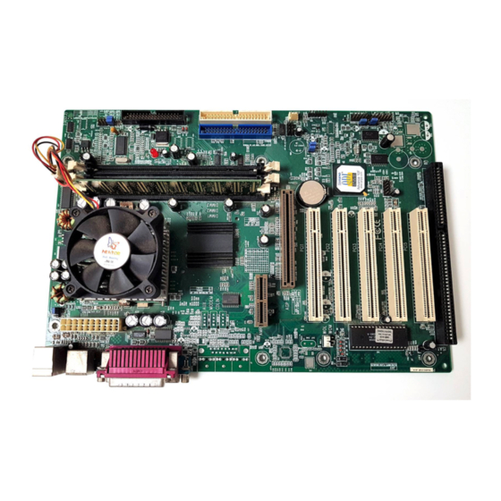
SynactiX 1 mainboard
QDI Driver CD 2000
I/O shield
1 IDE ribbon cable
1 floppy ribbon cable
1 9-pin ribbon cable with bracket for serial port 2 (manufacturing option)
1 spare jumper cap
QDI Serial Product R.M.A. Warranty Card
User's manual
Notice
The information in this document is subject to change in order to improve reliability, design,
or function without prior notice and does not represent a commitment on the part of this
company. In no event will we be liable for direct, indirect, special, incidental, or consequen-
tial damages arising out of the use or the possibility of such damages.
All trademarks are the property of their respective owners.
If you require further information, please visit our web-site: "www.qdigrp.com".
Advertisement
Table of Contents

Related Manuals for QDI SynactiX 1


Summary of Contents for QDI SynactiX 1
- Page 1 1 floppy ribbon cable 1 9-pin ribbon cable with bracket for serial port 2 (manufacturing option) 1 spare jumper cap QDI Serial Product R.M.A. Warranty Card User’s manual Notice The information in this document is subject to change in order to improve reliability, design, or function without prior notice and does not represent a commitment on the part of this company.
- Page 2 EN 50082-1 Generic immunity standard Part 1: Residential, commercial and light industry European Representative: QDI COMPUTER ( UK ) LTD QDI COMPUTER ( SCANDINAVIA ) A/S QDI SYSTEM HANDEL GMBH QDI COMPUTER ( NETHERLANDS) B. V. QDI COMPUTER (FRANCE) SARL QDI COMPUTER HANDELS GMBH QDI COMPUTER (ESPANA) S.A.
- Page 3 Declaration of conformity Trade Name: QDI Computer ( U. S . A. ) Inc. Model Name: SynactiX 1 Responsible Party: QDI Computer ( U. S. A.) Inc. Address: 41456 Christy Street Fremont, CA 94538 Telephone: (510) 668-4933 Facsimile: (510) 668-4966...
-
Page 4: Table Of Contents
C O N T E N T S SpeedEasy Quick Setup(English) ............S.1 SpeedEasy ............... S.3 Facilité de vitesse Initialisation(Francais) .......... S.5 1. Introduction ..............Overview .................... 1 Key Features ..................1 Introduction to New Features .............. 3 2. Installation Instructions ..........External Connectors .............. - Page 5 Integrated Peripherals ................33 PC Health Status ..................35 Password Setting ................. 37 Boot with BIOS defaults ..............37 Appendix A QDI Driver CD 2000 ............. 38 Appendix B Boot Logo ..............39 RecoveryEasy ..............41 Introduction ................... 41 Operation Process ................41...
- Page 6 DIMM sockets. If the LED is on, adding or removing devices like SDRAM memory is prohibited. Caution 2 Be sure to add some Silicone Grease between the PentiumIII (Coppermine) CPU and the FAN to keep them fully contact , meanwhile to meet the heat sink requirement. Manual for SynactiX 1...
-
Page 7: Speedeasy Quick Setup(English)
100MHz host bus speed, 200MHz for processor with 66MHz host bus speed, for bus ratio locked processor, run its real speed. 5. Save and exit BIOS Setup, your system will now boot successfully. Manual for SynactiX 1... - Page 8 The processor speed can be manually selected on the “CPU SpeedEasy SETUP” menu screen. Warning: Do not set CPU frequency higher than its working frequency. If you do, we will not be responsible for any damages caused. Manual for SynactiX 1...
- Page 9 Intel® Pentium III FC-PGA or Celeron™PPGA 370 BIOS CPU SpeedEasy Setup 1 3 3 C P U 4 0 0 1 0 0 C P U 3 0 0 C P U 2 0 0 C P U BIOS Manual for SynactiX 1...
-
Page 10: Speedeasy
SpeedEasy SpeedEasy CPU SpeedEasy Setup SpeedEasy BIOS jumper SpeedEasy Setup Manual for SynactiX 1... - Page 11 SynactiX 1 Installation de la carte mère SynactiX 1 Assurez-vous que votre ensemble est complet: carte mère, câbles IDE et FLOPPY, notice d’utilisation et CD-ROM d’installation. Vérifiez que l’alimentation est débranchée et reliez-vous à la terre par une courroie à votre poignet. A défaut, maintenez le contact de vos deux mains avec un objet lui-même relié...
- Page 12 Installation du SynactiX 1 système Installation du système. Démarrez votre système en pressant le bouton «POWER». Pressez la touche «Suppr» pour entrer dans le setup du BIOS. Dans le menu «SpeedEasy CPU Setup», réglez la vitesse de votre processeur (ATTENTION: il est recommandé de ne pas sélectionner une fréquence supérieure à...
- Page 13 Vous pouvez voir le contenu du CD-ROM Dans le répertoire Utility : A. AWDFLASH.EXE B. LF.EXE Dans le répertoire Documents : A. Adobe Acrobat Reader V3.0 – Ar32e301.exe B. Manuels français WinneX 1 et WinneX 3 – WX1FR.doc et WX3FR.doc Manual for SynactiX 1...
- Page 14 Installation du SynactiX 1 système Note: si vous ne déterminez pas la vitesse de votre unité centrale, votre système fonctionnera par défaut (400MHz pour les CPU avec une fréquence de Bus de 133MHz et 300MHz pour les CPU avec une fréquence de Bus de 100MHz et 200MHz pour les CPU à...
-
Page 15: Introduction
Introduction Introduction Overview SynactiX 1 green mainboard utilizes the Intel integrated graphics chipset — Intel® 815 Chipset, providing a fully compatible, high performanced and cost-effective PC/microATX platform. The new integrated technologies, together with the software configurable AC’97 audio and modem system give customers an advanced, multimedia solution at an ex- tremely low price. - Page 16 Provides onboard Line-in Jack, Microphone-in Jack, Speaker-out Jack and MIDI/Joy- stick Connector. AGP Interface AGP Universal Connector supports AGP 2.0 including 4x AGP data transfers. Advanced features PCI 2.2 Specification Compliant. Provides Trend ChipAwayVirus On Guard. Manual for SynactiX 1...
-
Page 17: Introduction To New Features
Onboard I/O Winbond 83627HF supports system monitoring (monitors CPU and system temperatures, system voltages, chassis intrusion and fan speed). Supports management applications such as QDI’s ManageEasy or LDCM (LANDesk Client Manager). (optional) Provides onboard 3.3V regulator to support ATX power supply without 3.3V output.(Optional) - Page 18 AWARD BIOS CMOS Setup. In this way, the BIOS can not be overwritten, but the DMI information can be updated. Refer to page 16 for detailed information on jumper setting, and page 28 for related BIOS setting. Manual for SynactiX 1...
- Page 19 Suspend-to-RAM status. For example, pushing the power button, through the Wake-on- LAN, Wake-on-Modem function or RTC Alarm. If the keyboard password power-on func- tion is enabled, the keyboard password should be used to wake up the system instead of pushing the power button. Manual for SynactiX 1...
- Page 20 The operating system must be capable of DMA transfers. Win95 (OSR2) and Win98 are capable. An Ultra ATA/66 capable, 40-pin, 80-conductor cable is required. Ultra ATA/66 compatible IDE device such as a hard drive or CD-ROM drive. Manual for SynactiX 1...
-
Page 21: Installation Instructions
The Microphone-in jack can be connected to a microphone for voice input. The Speaker- out jack allows you to connect speakers or headphones for audio output from the internal amplifier. The MIDI/Joystick connector allows you to connect a game joystick or a MIDI device. Manual for SynactiX 1... -
Page 22: Usb3, Usb4, Uart2
Microphone in USB3, USB4, UART2 SynactiX 1 provides one extra Front Panel USB header to connect to the front panel USB ports of your chassis. But you can only enable either back panel USB or front panel USB at one time. -
Page 23: Hard Disk Led Connector (Hd_Led)
The connector can be connected to the keyboard lock switch on the case for locking the keyboard. HD_LED HDD LED(+) HDD LED(-) ORANGE(-) GREEN(-) LED+(VCC) POWER SPKDATA RESET EMPTY EMPTY EMPTY LED+ SLEEP LED- LED- LED+ LED+ LED- KEYLOCK Manual for SynactiX 1... -
Page 24: Infrared Header (Irda)
LAN adapter, set “Wake-Up by LAN/Ring” as Enabled in the “POWER MANAGEMENT SETUP” section of the BIOS. Save & exit, then boot the operating system once to make sure this function takes effect. +5V standby Signal for waking up (active high) Manual for SynactiX 1... -
Page 25: Wake-Up On Internal Modem (Wom)
Sound Connector (PC-PCI) This connector provides a bridge between the mainboard and PCI sound card to deliver sound compatibility under DOS real-mode environment. PC-PCI DMA REQUEST SERIAL INTERRUPT REQUEST 2 4 6 1 3 5 PC-PCI DMA ACKNOWLEDGE Manual for SynactiX 1... -
Page 26: Pin Smbus Connector(Smbus)
Riser, or no audio with modem on the Riser. SynactiX 1 mainboard provides you with audio onboard solution, onboard audio can be enabled/disabled. Either AMR (Audio/Modem Riser) card or MR (Modem Riser) card can be used on this system. -
Page 27: Expansion Slots & I/O Ports Description
(Auto) (Normal Status) (Enable Audio) Closed (Connect PCI 3.3Vsb) (Optional) (Enable KB Power-on) JP26&JP27, (Back Panel USB Enabled) JP35&JP36 2-3 (Front Panel USB Enabled) JFUSB/JUSB (Enable Front/Back Panel USB Device Wake-up Function) Open (Enable Flash BIOS) Manual for SynactiX 1... -
Page 28: Clear Cmos
The mainboard provides the advanced keyboard password power-on function. Before using this function, set JKB with pin1 & pin2 closed. Otherwise, set JKB with pin2 & pin3 closed for disabling. Disable: 1 2 3 Enable: 1 2 3 Manual for SynactiX 1... - Page 29 Jumpers labeled JFS0 and JFS1 are located on the mainboard providing users with CPU overclocking feature. The host bus speed can be set as 66/100/133MHz or AUTO select. Refer to the chart below for the location of these jumpers, and the table for information on how to set them. Manual for SynactiX 1...
- Page 30 ROM in FWH. Whenever the system hardware configuration is changed, DMI informa- tion will be updated automatically. However, setting jumper JAV as closed makes flashing BIOS and updating DMI information impossible. Refer to page 4 for the two choices to implement BIOS-ProtectEasy. Manual for SynactiX 1...
- Page 31 ACPI S3 by activating USB device. Before using this function, set JFUSB/JUSB with pin1 & pin2 closed. Otherwise, set JFUSB/JUSB with pin2 & pin3 closed for disabling. JFUSB/JUSB JUSB Disable: 1 2 3 Enable: 1 2 3 JFUSB Front Panel USB Port (USB3.4) Manual for SynactiX 1...
Need help?
Do you have a question about the SynactiX 1 and is the answer not in the manual?
Questions and answers