
Related Manuals for Promation Engineering P1.A Series


Summary of Contents for Promation Engineering P1.A Series
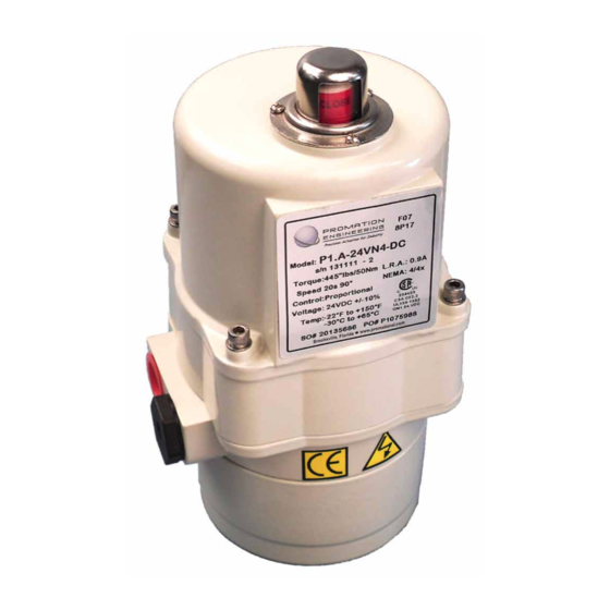
- Page 1 Installation & Operation Manual This IOM is for the following ProMation Engineering Products: P1.A-12VN4-AC P1.A-12VN4-DC P1.A-24VN4-AC P1.A-24VN4-DC...
- Page 2 This page intentionally left blank...
-
Page 3: Table Of Contents
Field Manual P1.A- Series LV AdVanced Proportional Control ISO5211 F05/07 8P17 Table of Contents 2 ....Product Specifications 3 ....Shipping and Handling 3 . -
Page 4: Product Specifications
Product Specifications P1.A Actuator Specifications Torque “lb/Nm 445”lbs/50Nm Supply Voltage 12vac/dc 24vac/dc Max Inrush Current 1.5A 0.9A Running Current 1.3A 0.8A Motor DC Brush Type Runtime (90°@60Hz/vdc) 20 sec Runtime (90 @50Hz) 20 sec Duty Cycle 75% maximum Motor Starts 1200 per hour Weight 7lbs/4kg (6.6lbs/3kg XOV) -
Page 5: Shipping And Handling
Shipping and Handling 1. This actuator is shipped in the FULLY CW (position indicator shows “CLOSE”) position. 2. NOTE, THIS ACTUATOR MUST HAVE WATER TIGHT EMT FITTINGS, WITH CONDUIT DRAINAGE INSTALLED AND POWER SUPPLIED TO UNIT TO KEEP THE HEATER WARM AT THE TIME OF INSTALLATION. 3. -
Page 6: Wiring Diagram
Wire sizing data is provided in the Wire Sizing Data table to assist in the selection of Gage the proper wire size for ProMation P1.A series actuators using various wire sizes over distance. Please make sure to reference the correct voltage and do not exceed the indicated length of the wire run for each model. -
Page 7: Layout Of Controller
Layout of Controller Proportional Control Signal Reversed Indicator (Orange LED) Diagnostics (Blue LED) Calibration Button 5 position DIP Switch DIP 5 Running CW Indicator (Red LED) Running CCW Terminal Block Power Indicator(Green LED) (Yellow LED) 4 Pin Connector 3 Pin Connector to Switch Card to Potentiometer P1 24VN4-DC Shown... -
Page 8: Check End Of Travel Settings
Check End of Travel Settings Check End of Travel Settings The actuators are tested, calibrated and shipped in the Full CW position in the Direct Acting mode (CW is 4mA, CCW is 20mA). End of Travel cams are set at 90 degrees from each other. A. -
Page 9: Adjusting The Actuator Ccw And Cw Positions
Adjusting the actuator CCW and CW positions (Cam adjustment) Remove power from this device BEFORE making any End of Travel cam adjustments. Cam 1 Adjustment 1. The lower cam is Cam 1, the CCW end-of-travel adjustment. Once the actuator is at its required CCW position, with POWER OFF, use a 2.5mm hex key to free up the cam set screw. -
Page 10: Adjusting The Actuator Auxiliary Switches
Adjusting the actuator Auxiliary Switches Remove power from this device BEFORE making any End of Travel cam adjustments. Cam 3 Adjustment 3. The third cam is Cam 3, the CCW auxiliary switch adjustment. Drive the actuator to its CCW position. Then use a 2.5mm hex key to free up the cam set screw. - Page 11 ProMation Engineering, Inc. 4/25/2013 ked By Page 9 of 14 P1.A LV AdVanced Proportional Series Last Checked: Dwg. Name P1A F07 8P17 DimData.idw 4/15/2014 This Document is the property of ProMation Engineering, Inc. Distribution of this document without the written Finish...
-
Page 12: Mechanical Data
Mechanical Data P1.A Series Exploded View (P1-120VN4 unit is shown) Position indicator viewport Aluminum Casting NEMA 4X Protection Easily distinguishable yellow/red position indicator Proportional Control Card Spacer Heavy Duty Drive Motor NEMA 4X Cover Seals Switch Card Switch Logic Map and... -
Page 13: Commissioning
Commissioning This procedure will assume that the actuator is installed correctly both mechanically and electrically with correct power at terminals marked 4 & 5 and control signal at terminals marked 6 & 7 1. Apply the correct supply power to the actuator. (DIP 5 ON) •... -
Page 14: Calibration Procedure
Calibration Procedure: AdVanced Controller Calibration Were CW or CCW End of Travel cams changed from factory settings? Calibration is not necessary Is power supplied to the board? Actuator may be put into service Wire the actuator per Set DIP 5 to OFF the wiring diagram Use Wire to Jumper connector pins 7 and 12... - Page 15 DIAG DIAG Steady Is the Blue LED Blinking ON steady? Potentiometer Pass Potentiometer Fail Cycle DIP 1 OFF 1. Loosen then back ON to potentiometer Calibrate Feedback drive gear (2.5mm hex) Actuator will start the 2. Adjust Feedback calibration gear slowly routine: until Blue LED stops...
- Page 16 DIAG DIAG Did the Blue LED 20Hz Blink 20Hz Blink 30 seconds 3 seconds fl ash at 20Hz for three (3) seconds? Feedback Calibration Pass Feedback Calibration Fail DIAG Blue LED now blinks at DIAG 1Hz rate indicating no Blue LED now blinks at control signal input 1Hz Blink 1Hz rate indicating no...
- Page 17 ProMation Engineering, Inc. 16138 Flight Path Drive Brooksville, FL 34604 Phone (352) 544-8436 Fax (352) 544-8439 www.promationei.com...
- Page 18 ProMation Engineering can provide design and technical services for OEM’s, projects with customized requirements and specialized operations. ProMation Engineering follows a policy of continual product updates and enhancements. Our website is the best place to obtain the latest product documentation, including the wiring diagrams for these controllers.
Need help?
Do you have a question about the P1.A Series and is the answer not in the manual?
Questions and answers