Advertisement
Quick Links
Advertisement

Subscribe to Our Youtube Channel
Related Manuals for Promation Engineering P7-24PN4-DC


Summary of Contents for Promation Engineering P7-24PN4-DC
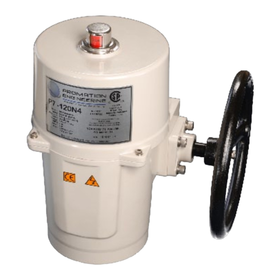
- Page 1 Installation & Operation Manual This IOM is for the following ProMation Engineering Products: P7-24PN4-DC P7S-24PN4-DC P8-24PN4-DC P8S-24PN4-DC Valid for the following Options -TS - Torque Switch equipped - IP68 compatible enclosure -SS - Stainless Steel enclosure...
-
Page 2: Table Of Contents
Field Manual P7,8(S) 24PN4-DC (-TS) High Resolution Proportional Control Powered Feedback ISO5211 F12 8P36 Imperial Mount S 5in/6 BHC P7 1.375in Shaft, 0.3125 in sq key P8 1.625in Shaft, 0.375 in sq key Contents 2 ....Product Specifications 3 . -
Page 3: Product Specifications
Product Specifications Actuator Specifi cations Torque “lb/Nm 8900”lbs/1000Nm 13250”lbs/1500Nm These may be equipped with internal Supply Voltage 24vac/vdc 24vac/vdc torque switches (-TS) which protect Max Inrush Current 7.8A 8.0A the gear train, motor and controlled Running Current 7.0A 7.5A Motor DC Brush Type equipment from damage when high Runtime (90°@60Hz/vdc) -
Page 4: Shipping And Handling
Shipping and Handling 1. This actuator is shipped in the FULLY CW position (2 color position indicator shows “CLOSE” and the Reference Dimple aligns with “0”). (The “1” mark is the FULLY CCW position). 2. NOTE, THIS ACTUATOR MUST HAVE WATER TIGHT EMT FITTINGS, WITH CONDUIT DRAINAGE INSTALLED AND POWER SUPPLIED TO UNIT TO KEEP THE HEATER WARM AT THE TIME OF INSTALLATION. -
Page 5: Wiring Diagram
Wiring Diagram Proportional Control Actuator Specifi cations Torque “lb/Nm 8900”lbs/1000Nm 13250”lbs/1500Nm Optional torque switch wiring (-TS) is interposed Supply Voltage 24vac/vdc 24vac/vdc between motor end of travel wiring and controler Max Inrush Current 7.8A 8.0A Running Current 7.0A 7.5A Motor DC Brush Type Runtime (90°@60Hz/vdc) 46 sec... - Page 6 Diagram of Controller Proportional Control The AC Controller Shown. Calibration sequence is the same for both AC and DC J7 Connector J1 Connector J2 Connector Calibration Menu Fuse J3 Connector for Optional Select ▲ Feedback Button or Modbus Control Options MODE Button For MODBUS...
- Page 7 Setting Limit Switches and Auxiliary Switches (Cams) This actuator has been factory calibrated to operate between 0 degrees and 90 degrees. Proportional Controller positioning changes diff erent from 0 and 90 degrees will likely involve also changing cam settings. If cam adjustments cause the controller board to show faults, you will need to reposition the cam further outside your range of travel.
- Page 8 Cam Adjustments Listed here for reference. Mechanical stops must be out before changing cam settings. Proceed ONLY if adjustments are required. Adjust Cam 1 (SW1 -- CW limit switch) The lowest cam is Cam 1, the CW limit switch (SW1) cam. Once the actuator is at its required CW position turn POWER OFF.
- Page 9 Pre Calibration Preparation This procedure will assume that the actuator is installed correctly both mechanically and electrically with correct POWER and SIGNAL, the cams are factory set 1-2° beyond 0° and 90°, and the mechanical stop screws are out. Calibration - End of Travel, Feedback This proportional control...
- Page 10 Calibrating the proportional control board Calibration Interface Notes The AUTO LED is lit during normal operation. Pressing MODE will enter the calibration sequence to change operational parameters. The MODE sequence goes in one direction. Each time MODE is pressed the current parameter is saved and the next one is presented.
- Page 11 Calibrating the proportional control board (continued) 6. Set Open (CCW) Position (OPEN LED is lit) The motor will drive to approximately the 75% position. Use the handwheel or the ▲ and ▼ to position the actuator in the desired OPEN position (i.e. 20 mA). (You must touch either ▲ or ▼before the handwheel responds).
- Page 12 Calibrating the proportional control board (continued) 10. Set Loss of Signal (LOSS OF COMMAND LED is lit) 10.A Use ▲ and ▼ to select the fail position on loss of signal. Select from the column right of the LEDs. • CLOSE - fails close (4mA) • OPEN - fails open (20mA) • (Both Off ) - fails in place (default) 10.B Press MODE to set...
- Page 13 Complete Calibration AUTO LED is lit. The actuator is now responding to the 4-20mA signal. Calibration is complete. Reinstall mechanical stop screws. • CCW Stop - drive to the OPEN position and power down actuator. • With handwheel, drive more open until you hear the SW2 switch make.
- Page 14 Motor Amperage Limiter The DC controllers are equipped with adjustable amperage limiting that is set by the rotational potentiometer adjacent to the J7 connector. The amperage draw on the motor is limited by the aperage setting as shown in the inset. TThe setting should be adjusted to a reasonalb elevel above the running current expected for the actuator and its load.
- Page 15 Commissioning After completing all mounting and wiring procedures and main power is available, it is now possible to commission the actuator. 1. Utilize the handwheel to rotate the actuator and damper, valve or other connected device through its full travel from full CW to full CCW and back again to check for any possible interference.
- Page 16 Commissioning for TS units (continued) Torque Switch CCW Mechanical Operation 1. Rotate the manual override handwheel in a CCW direction to continue to drive the output drive in a CCW direction until the drive system reaches the end of its MECHANICAL travel either by coming into contact with the mechanical stop screw OR it reaches the end of the valve (or damper) travel.
-
Page 17: Mechanical Data
1.0" 36.00 - .13 49.00 mm 0.000 1.417 - 0.005 1.929 in 45.00 mm 36.00 - .13 F12 ISO Flange 36.00 mm 1.772 in 0.000 1.417 - 1.417 in Depth 0.005 Square Part No. Created: ProMation Engineering, Inc. 5/2/2013... - Page 18 5/2/2013 Checked By Last Checked: Dwg. Name 1/4/2022 P7_8S 3.5in w key DimData.idw This Document is the property of ProMation Engineering, Inc. Distribution of this document without the written Material Finish Rev. consent of the owner is Strictly forbidden. P7~P8S Imperial Dim Data Failure to comply will incur a liability for Damages.
Need help?
Do you have a question about the P7-24PN4-DC and is the answer not in the manual?
Questions and answers