
Related Manuals for Promation Engineering P2-120N4-RC


Summary of Contents for Promation Engineering P2-120N4-RC
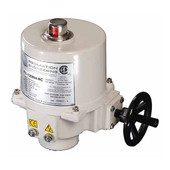
- Page 1 Installation & Operation Manual This IOM is for the following ProMation Engineering Products: P2-120N4-RC P2-230N4-RC P3-120N4-RC P3-230N4-RC...
- Page 2 This page intentionally left blank...
-
Page 3: Position Control
Field Manual P2/3 HV-RC 2 Position Control ISO5211 F07 8P22 - 1 2 0 N 4 - R C Table of Contents 2 . . . . . . . . . . . . . . . . . . . Product Specifications 3 . - Page 4 Operation of Relay to Close Actuator Specifi cations (-RC ) Actuator Torque “lb/Nm 800”lbs/90Nm 1335”lbs/150Nm Supply Voltage 12vac/vdc 24vac/vdc 12vac/vdc 24vac/vdc This unit is designed to drive FULLY Max Inrush Current 5.2A 4.5A 4.9A 5.0A CLOSED (CW) when power is applied Running Current 3.4A 2.2A...
-
Page 5: Shipping And Handling
Engineering for a multiple actuator parallel wiring diagram. NE PAS mettre en parallèle des actionneurs multiples simultanément sans utiliser de relais d’isolement! Contactez ProMation Engineering pour un diagramme de câblage parallèle à plusieurs actionneurs. Page 3 of 10 P2/3 HV-RC 2 Position Series... - Page 6 On/Off Control Actuator Specifi cations Torque “lb/Nm 800”lbs/90Nm 1335”lbs/150Nm Supply Voltage 120vac 230vac 120vac 230vac Max Inrush Current 1.8A 0.8A 1.8A 1.2A Running Current 1.0A 0.5A 1.2A 1.0A Motor Split Phase Capacitor Runtime (90°@60Hz/vdc) 15 sec 22 sec Runtime (90 @50Hz) 17 sec 26 sec...
- Page 7 Serious Damage to the actuator will result if the motor is allowed to drive the gear train into the mechanical stop!! Remove power from this device BEFORE making any travel adjustments. This actuator has been factory calibrated to operate between 0 degrees and 90 degrees. Most quarter-turn products will not require recalibration of these settings.
- Page 8 Serious Damage to the actuator will result if the motor is allowed to drive the gear train into the mechanical stop!! Remove power from this device BEFORE making any travel adjustments. This actuator has been factory calibrated to operate between 0 degrees and 90 degrees. Most quarter-turn products will not require recalibration of these settings.
- Page 9 Adjust Cam 3 1. The THIRD cam is Cam 3, the CW auxiliary switch adjustment. Drive the actuator to its CW position. Then use a 2.5mm hex key to free up the cam set screw. Once it is free, rotate the hex key to the RIGHT 10-15 degrees to reset the switch roller arm.
- Page 10 Created: ProMation Engineering, Inc. 4/25/2013 Page 8 of 10 P2/3 HV-RC 2 Position Series Last Checked: Dwg. Name P2_3 F07 8P22 DimData.idw 4/8/2015 This Document is the property of ProMation Engineering, Inc. Distribution of this document without the written Finish...
- Page 11 P Series Exploded View (P2/3-120N4 unit is shown) Easily distinguishable yellow/red position Aluminum Casting indicator NEMA 4X Protection Heavy Duty Drive Motor Modular Easily accessible Control switch & cam stacks Cards Aluminum Casting NEMA 4X Protection NEMA 4X Cover Seal Worm Drive Switch Logic Map and Switch/Cam Arrangement...
- Page 12 After completing all mounting and wiring procedures and main power is available, it is now possible to commission the actuator. 1. Utilize the handwheel to rotate the actuator and damper, valve or other connected device through its full travel from fully CW to fully CCW and back again to check for any possible interference.
- Page 13 ProMation Engineering, Inc . 16138 Flight Path Drive Brooksville, FL 34604 Phone (352) 544-8436 Fax (352) 544-8439 www .promationei .com...
-
Page 14: Industrial Applications
ProMation Engineering can provide design and technical services for OEM’s, projects with customized requirements and specialized operations. ProMation Engineering follows a policy of continual product updates and enhancements. Our website is the best place to obtain the latest product documentation, including the wiring diagrams for these controllers.
Need help?
Do you have a question about the P2-120N4-RC and is the answer not in the manual?
Questions and answers