Table of Contents
Advertisement
Quick Links
Installation & Operation
This IOM is for the following
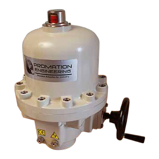
ProMation Engineering Products:
P2-120PN7
P2-230PN7
P3-120PN7
P3-230PN7
Manual
This product is certified for use in the
following hazardous locations:
Class I, Division 1, Groups C, D
Class II, Division 1, Groups E, F, and G
Class III; T6 (85 °C)
Ex d IIB Gb T6; Ex tb IIIC T85°C Db
Class I, Zone 1, AEx d IIB Gb T6
Zone 21, AEx tb IIIC T85°C Db
and requires procedures and equipment rated
for installation in those areas.
®
C
US
238703
Advertisement
Table of Contents

Subscribe to Our Youtube Channel
Related Manuals for Promation Engineering P2 Series


Summary of Contents for Promation Engineering P2 Series
- Page 1 Class I, Zone 1, AEx d IIB Gb T6 238703 Zone 21, AEx tb IIIC T85°C Db and requires procedures and equipment rated for installation in those areas. This IOM is for the following ProMation Engineering Products: P2-120PN7 P2-230PN7 P3-120PN7 P3-230PN7...
-
Page 2: Hazardous Location Actuators
Class I, Division 1, Groups C, D Class II, Division 1, Groups E,F,G Class III; T6 CAUTION: To reduce the risk of ignition of hazardous atmospheres, disconnect the Label 810-10174 is equipment from the supply circuit before opening. Keep assembly tightly closed when in operation. -
Page 3: Table Of Contents
Field Manual P2/3 HV-PN7 Proportional Control ISO5211 F07 8P22 ® 238703 * This IOM contains information for units without Torque Switches ONLY. Table of Contents 1 . . . . . . . . . . . . . . . . . . . . . . . .Hazardous Location Actuators 3 . -
Page 4: Product Specifications
Actuator/ Duty cycle can be calculated as follows: Voltage 120VAC 230VAC 120VAC 230VAC (example P2 series actuator running 3 seconds ON and 30 seconds OFF) Amps Wire 1.8A 0.8A 1.8A 1.2A Runtime = 3s, Total time = 3s + 30s = 33s, therefore this duty cycle would be 9% (3/33) -
Page 5: Shipping And Handling
Shipping and Handling 1. This actuator is shipped in the FULLY CW position (2 color position indicator shows REFERENCE “CLOSE” and the Reference Dimple aligns with “0”). (The “1” mark is the FULLY DIMPLE CCW position). “1” = CCW “0” = CW 2. -
Page 6: Wiring Diagram
P23 HV PN7 Wiring Diagram for P2~3 Series Proportional Control Actuator Specifi cations Torque “lb/Nm 800”lbs/90Nm 1335”lbs/150Nm Supply Voltage 120vac 230vac 120vac 230vac Max Inrush Current 1.8A 0.8A 1.8A 1.2A Running Current 1.0A 0.5A 1.2A 1.0A Motor Split Phase Capacitor FEEDBACK OUT Runtime (90°@60Hz) 15 sec... - Page 7 * The P2/3 PN7 Series is NOT available with the Torque Switch option. Page 6 P2/3 HV-PN7 Series...
-
Page 8: Diagram Of Controller
Signal Connection Diagram of Controller Proportional Control Signal Connections Thermal Sensor Ribbon Cable Thermal Sensor Thermal Sensor Connector Connector Joystick Signal Connection Fault Status Fault Status (red LED) Voltage Joystick Select Joystic Fault Status Voltage Sel Voltage Select Settings Driving Closed Joystick Functionality Driving Closed 5A Fuse... -
Page 9: Controller: Initial Startup
Controller: Initial Startup These instructions illustrate the initial power up sequence for power up, initial data displays, and position display so the user has a baseline for proper startup sequencing. (Assumes actuator is properly mounted and wired as directed elsewhere in this manual). Power Up 4 digit display reads: How the display behaves... -
Page 10: Controller: Adjusting The Actuator Cw Position
Controller: Adjusting the actuator CW position Follow these instructions to adjust the CW position controlled by the 105 Proportional Controller (standard operation). Proceed to the next page to adjust the CW position controlled by the travel cam. (Assumes actuator is powered up, running and is at the default display, showing position). realtiOe Press the joystick LEFT twice... -
Page 11: Adjusting The Actuator Cw Position
Adjusting the actuator CW position Serious Damage to the actuator will result if the motor is allowed to drive the gear train into the mechanical stop!! Remove power from this device BEFORE making any travel adjustments. This actuator has been factory calibrated to operate between 0 degrees and 90 degrees. Most quarter-turn products will not require recalibration of these settings. -
Page 12: Controller: Adjusting The Actuator Ccw Position
Controller: Adjusting the actuator CCW position Follow these instructions to adjust the CCW position controlled by the 105 Proportional Controller (standard operation). Proceed to the next page to adjust the CCW position controlled by the travel cam. (Assumes actuator is powered up, running and is at the default display, showing position). realtiOe Press the joystick LEFT twice... -
Page 13: Adjusting The Actuator Ccw Position
Adjusting the actuator CCW position Serious Damage to the actuator will result if the motor is allowed to drive the gear train into the mechanical stop!! Remove power from this device BEFORE making any travel adjustments. This actuator has been factory calibrated to operate between 0 degrees and 90 degrees. Most quarter-turn products will not require recalibration of these settings. -
Page 14: Controller: Change Loss Of Signal Response Setting
Controller: Change Loss of Signal Response Setting (Assumes actuator is powered up, running and is at the default display, showing position). Notice: Any changes, settings or new calibration points are lost if a factory “Reset” is performed on the controller. Contact the factory for details. realtime Press the joystick LEFT twice... -
Page 15: Controller: Auto-Calibration Procedure
Controller: Auto-Calibration Procedure (Assumes actuator is powered up, running and is at the default display, showing position). Notice: Any changes, settings or new calibration points are lost if a factory “Reset” is performed on the controller. Contact the factory for details. realtiOe Press the joystick LEFT twice... -
Page 16: Adjusting The Actuator Auxiliary Switches
Adjusting the actuator Auxiliary Switches Adjust Cam 3 1. The THIRD cam is Cam 3, the CW auxiliary switch adjustment. Drive the actuator to its CW position. Then use a 2.5mm hex key to free up the cam set screw. Once it is free, rotate the hex key to the RIGHT 10- 15 degrees to reset the switch roller arm. -
Page 17: Mechanical Data
Dimensional Data P2~8-N7 Series Actuators: inches (mm) 8/13/2014 Checked By Last Checked: Dwg. Name P2~P8 TS Ex Generic DimData.idw 11/12/2014 This Document is the property of ProMation Engineering, Inc. Distribution of this document without the written P2~P3 Material 14.0 (355) Finish 15.5 (392) 9.0 (229) 10.5 (267) -
Page 18: Mechanical Data
Mechanical Data P Series Exploded View (P2/3-120N7 unit is shown) Easily distinguishable yellow/red position indicator Aluminum Casting, Class 1 / Div 1 Class 2 / Div 1 Protection Alignment Heavy Duty Pins (2) Drive Motor Easily accessible Modular switch & cam stacks Control Cards Aluminum Casting... -
Page 19: Commissioning
Commissioning After completing all mounting and wiring procedures and main power is available, it is now possible to commission the actuator. 1. Utilize the handwheel to rotate the actuator and damper, valve or other connected device through its full travel from fully CW to fully CCW and back again to check for any possible interference. - Page 20 ProMation Engineering can provide design and technical services for OEM’s, projects with customized requirements and specialized operations. ProMation Engineering follows a policy of continual product updates and enhancements. Our website is the best place to obtain the latest product documentation, including the wiring diagrams for these controllers.
Need help?
Do you have a question about the P2 Series and is the answer not in the manual?
Questions and answers