Advertisement
Quick Links
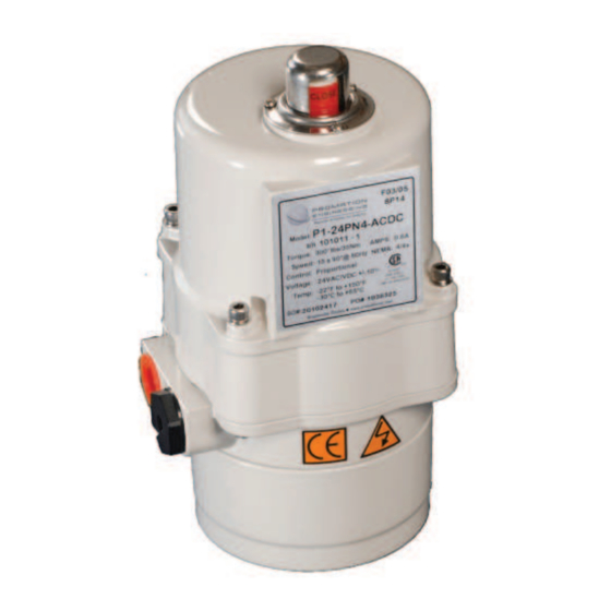
PROMATION
ENGINEERING
Precision Actuation for Industry
...Partners, Above and Beyond
Actuator Specifi cations
Torque lb/Nm
Supply Voltage
Max Inrush Current
Running Current
Runtime (90
@60/50Hz)
O
Weight
Mechanical Connections
Electrical Entry
Electrical Terminations
Environmental Rating
Manual Override
Control
Case material
Motor Protection (On/Off)
120vac or 230vac Operation
Motor Protection
12v/24v AC/DC
Ambient Temperature
Operating Range
The following procedure is to be followed for set-up, calibration, testing and use of the P1 Series Proportional Control
quarter-turn electric actuators. Each unit is shipped from the factory with initial calibration of cams and switches completed.
However, these are general settings and serve as a starting point for proper calibration of the actuator in its' real-world
application.
Note: The P1.A-XOV actuator out put shaft drives CW to close (as viewed from above). However, the indicator
shaft turns CW to open (as viewed from above).
Determine if any adjustments are required
and control connections per the wiring diagram on page 2. Apply power to the actuator and wait 20 seconds for the
controller to power up.
The proportional control card has been calibrated and tested at the factory to provide full scale response between
0 degrees and 90 degrees operating range. Typically all that is required is a power supply and a control signal to
initialize and put the actuator into service with no need for any adjustments.
Important Note:
THIS ACTUATOR MUST HAVE THE EMT FITTINGS WATER TIGHT WITH CONDUIT DRAINAGE INSTALLED A N D
POWER SUPPLIED TO UNIT TO KEEP THE HEATER WARM AT THE TIME OF INSTALLATION .
This unit should NOT be stored outside unless it is powered up.
When this unit is NOT powered up, it should be stored in a clean, dry environment at all times.
Conventions used in this manual:
1. All references to rotation are as viewed from ABOVE the actuator.
The default settings in the controller are as follows:
1. Input/Output Signal: 4-20mA (unless otherwise specifi ed at time of Factory order)
2. Signal Response:
3. Loss of Signal:
P1.A..P-XOV
445"lbs / 50Nm
12vac/vdc
24vac/vdc
120vac
1.5A
3.0A
0.8A
0.5A
0.6A
0.5A
15sec
12sec / 13sec
7lbs / 3.2kg
ISO5211 F07 8pt 17mm
(2) 1/2" NPT
14 - 18 Ga.
4, 4X
none available
Proportional
Aluminum Alloy, Powder Coated
DC Brush Type
O
O
275
F/135
C Thermal H Class
o
o
-22
F to +150
F
o
o
-30
C to +65
C
This design utilizes NO MECHANICAL stops.
BEFORE
making any changes to cams or controller settings. Make the power
Direct Acting (max signal = OPEN)
Fail in Position
Page 1 of 6 P1.A..P-XOV Series
P1.A..P-XOV Series
Proportional Control
230vac
1.0A
0.3A
Field Manual
ISO5211 F07 8P17
Advertisement

Subscribe to Our Youtube Channel
Related Manuals for Promation Engineering P1 A P-XOV Series


Summary of Contents for Promation Engineering P1 A P-XOV Series
- Page 1 Field Manual PROMATION P1.A..P-XOV Series ENGINEERING Proportional Control Precision Actuation for Industry ...Partners, Above and Beyond ISO5211 F07 8P17 Actuator Specifi cations P1.A..P-XOV Torque lb/Nm 445”lbs / 50Nm Supply Voltage 230vac 12vac/vdc 24vac/vdc 120vac Max Inrush Current 1.5A 1.0A 3.0A 0.8A Running Current 0.5A...
-
Page 2: Connections And Settings
Connections and Settings- 1. The actuator is shipped from the factory in 2. Remove the four screws from the BOTTOM its fully CLOSED position. This can be verifi ed of the enclosure casting to facilitate the by viewing the indicator on the TOP of the removal of the cover and spacer casting. - Page 3 Calibration- 4. With the power OFF, set the 8 position DIP switch for proper operation. For 4-20mA Input, 1 is ON, 2 is OFF (default) For 1-5vdc Input, 1 is OFF, 2 is OFF For 2-10vdc INput, 1 is OFF, 2 is ON For 4-20mA Feedback, 3 is OFF, 4 is ON, 5 is OFF (default) For 2-10vdc Feedback, 3 is ON, 4 is OFF, 5 is ON For Direct Acting (5v/10v/20mA = OPEN) 6 is OFF (default)
- Page 4 8. Place hex wrench in the #3 cam set screw, loosen and move cam back clockwise and then counterclockwise into the switch until the switch “clicks”. Then move 1 degree further into the switch and snug up on the set screw. This will assure the aux switch will “trip” before the actuator reaches it’s end of travel.
-
Page 5: Application Notes
Application Notes: 1. These actuators are designed to be used in either a horizontal or upright position. Do NOT mount the actuator with the top below a horizontal position. 2. When installing conduit, use proper techniques for entry into the actuator. Use drip loops to prevent conduit condensate from entering the actuator. - Page 6 PROMATION ENGINEERING Precision Actuation for Industry 16138 Flight Path Drive Brooksville, FL 34604 Phone (352) 544-8436 Fax (352) 544-8439 email: jeff.jones@promationei.com / brian.wheeler@promationei.com Sales and Marketing: Jeff Jones Product Management: Brian J. Wheeler www.promationei.com Page 6 of 6 P1.A..P-XOV Series...
Need help?
Do you have a question about the P1 A P-XOV Series and is the answer not in the manual?
Questions and answers