Table of Contents
Advertisement
Quick Links
FOR YOUR SAFETY
If you smell gas:
1. Open windows.
2. DO NOT try to light any appliance.
3. DO NOT use electrical switches.
4. DO NOT use any telephone in
your building.
5. Extinguish any open flame.
6. Leave the building.
7. Immediately call your local gas
supplier after leaving the building.
Follow the gas supplier's
instructions.
8. If you cannot reach your gas
supplier, call the Fire Department.
WARNING
Fire Hazard
Keep all flammable objects, liquids and
vapors the minimum required clear-
ances to combustibles away from
heater.
Some objects will catch fire or explode
when placed close to heater.
Failure to follow these instructions can
result in death, injury or property
damage.
WARNING
Improper installation, adjustment, alteration, service
or maintenance can result in death, injury or
property damage. Read the Installation, Operation
and Service Manual thoroughly before installing or
servicing this equipment.
Installation must be done by a contractor qualified
in the installation and service of gas-fired heating
equipment or your gas supplier.
© 2018 Roberts-Gordon LLC
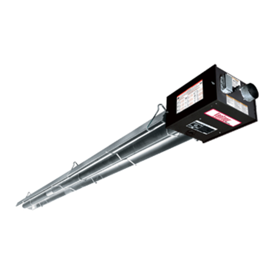
Model HEM
Gas-Fired, Low
Unitary Heater
Installation, Operation &
Please take the time to read and understand
these instructions prior to any installation.
Installer must give a copy of this manual to the owner.
Keep this manual in a safe place in order to provide
your service technician with necessary information.
Roberts-Gordon LLC
1250 William Street
P.O. Box 44
Buffalo, New York 14240-0044
Telephone: +1.716.852.4400
Fax: +1.716.852.0854
Toll Free: 800.828.7450
www.robertsgordon.com
Intensity
Service Manual
HEM-80
HEM-115
HEM-150
HEM-200
Installer
Owner
P/N 139100NA Orig 08/18
Advertisement
Table of Contents
Troubleshooting

Related Manuals for Roberts Gorden Vantage HEM-80


Summary of Contents for Roberts Gorden Vantage HEM-80
- Page 1 FOR YOUR SAFETY If you smell gas: 1. Open windows. 2. DO NOT try to light any appliance. 3. DO NOT use electrical switches. 4. DO NOT use any telephone in Model HEM your building. 5. Extinguish any open flame. 6.
-
Page 3: Table Of Contents
TABLE OF CONTENTS SECTION 1: Heater Safety............. 1 10.2 Central and Satellite Heaters (Zoning Capability) ..46 1.1 Manpower Requirements ..........1 10.3 Communication Wiring within a Zone of Heaters ..48 1.2 Safety Labels and Their Placement ......1 10.3 Communication Wiring within a Zone of Heaters 1.3 California Proposition 65 .......... -
Page 5: Section 1: Heater Safety
SECTION 1: H EATER AFETY SECTION 1: HEATER SAFETY 1.1 Manpower Requirements Your Safety is Important to Us! To prevent personal injury and damage to the heater, This symbol is used throughout two persons will be required for installation. the manual to notify you of possi- ble fire, electrical or burn hazards. - Page 6 HEM-S ERIES NSTALLATION PERATION AND ERVICE ANUAL FIGURE 1: Top and Bottom Panel Label Placement Logo Label Rating Plate Label Bottom Panel Gas Connection Label 45° Top Panel Vent Length Label Description Part Number Gas Connection Label Logo Label 91013221 45°...
- Page 7 SECTION 1: H EATER AFETY FIGURE 2: Side and Back Panel Label Placement 45° Tilt Reflector Level Reflector* Réflecteur U-Tube,Full 45° Réflecteur droit* incliné à 45° Tube en U à plein 45° Lower Shield** One Side Reflector Écran protecteur** U-Tube, Level Réflecteur à...
-
Page 8: Section 2: Installer Responsibility
HEM-S ERIES NSTALLATION PERATION AND ERVICE ANUAL SECTION 2: INSTALLER RESPONSIBILITY Model number and installed configuration are found on the burner and in the Installation, Operation and The installer is responsible for the following: Service Manual. See Page 5, Figure 3 through Page •... -
Page 9: Section 3: Clearances To Combustibles
SECTION 3: C LEARANCES TO OMBUSTIBLES SECTION 3: CLEARANCES TO COMBUSTIBLES WARNING 3.1 Required Clearances to Combustibles Clearances are the required distances that combustible objects must be away from the heater to prevent serious fire hazards. Combustibles are materials, that may catch on fire and include common items such as wood, paper, rubber, fabric, etc. - Page 10 HEM-S ERIES NSTALLATION PERATION AND ERVICE ANUAL NOTE: 1. All dimensions are from the surfaces of all tubes, couplings and elbows. 2. Clearances B, C and D can be reduced by 50% after 25' (7.5 m) of tubing downstream from where the burner and burner tube connect. FIGURE 4: ONE SIDE REFLECTOR (inches) (centimeters)
- Page 11 SECTION 3: C LEARANCES TO OMBUSTIBLES NOTE: 1. All dimensions are from the surfaces of all tubes, couplings and elbows. 2. Clearances B, C and D can be reduced by 50% after 25' (7.5 m) of tubing downstream from where the burner and burner tube connect. FIGURE 7: U-TUBE, LEVEL REFLECTOR (inches) (centimeters)
- Page 12 HEM-S ERIES NSTALLATION PERATION AND ERVICE ANUAL NOTE: 1. All dimensions are from the surfaces of all tubes, couplings and elbows. 2. Clearances B, C and D can be reduced by 50% after 25' (7.5 m) of tubing downstream from where the burner and burner tube connect. FIGURE 10: 2-FOOT DECO GRILLE AND PROTECTIVE GRILLE (inches) (centimeters)
-
Page 13: Section 4: National Standards And Applicable Codes
SECTION 4: N ATIONAL TANDARDS AND PPLICABLE ODES SECTION 4: NATIONAL STANDARDS AND APPLICABLE CODES 4.1 Gas Codes 4.3 Public Garages The type of gas appearing on the nameplate Installation in garages must be in accordance must be the type of gas used. Installation must with the following codes: comply with national and local codes and United States: Refer to Standard for Parking... -
Page 14: Section 5: Major Components
HEM-S ERIES NSTALLATION PERATION AND ERVICE ANUAL SECTION 5: MAJOR COMPONENTS FIGURE 13: Major Component Descriptions - Standard Reflector Standard Burner with Tube Gasket Reflector Must be installed with the (Aluminum or flame observation Stainless window facing down. Steel) Alternate overlap as shown on overview and on Page 19, Figure 18. - Page 15 SECTION 5: M AJOR OMPONENTS FIGURE 14: Major Component Descriptions - High Efficiency Reflector High Efficiency Reflector Burner with Tube Gasket (Aluminum) Must be installed with the Alternate overlap as shown on flame observation overview and on Page 19, window facing down. Figure 18.
-
Page 16: Standard Parts List
HEM-S ERIES NSTALLATION PERATION AND ERVICE ANUAL 5.1 Standard Parts List Table 1: Contents of the Burner Carton Part No. Description HEM-80 HEM-115 HEM-150 HEM-200 039XXXXX Burner Assembly (Rate and Fuel Varies) 02568200 Gasket (Burner to Burner Tube) 138100NA Installation, Operation and Service Manual 03700009 Combustion Air Weather Vent 94273914... - Page 17 SECTION 5: M AJOR OMPONENTS Table 3: Contents of High Efficiency Core and Extension Packages Core Packages Extension Packages Aluminized Aluminized Part No. Description (3m) (6m) (9m) (12m) (3m) (6m) (9m) (12m) 91409408 Tube, HT Aluminized, 10 (3 m) 03051101 Burner Tube, ALUMI-THERM Steel, 10 (3 m) ®...
- Page 18 HEM-S ERIES NSTALLATION PERATION AND ERVICE ANUAL Table 4: Component Package Guide Tubing Length Standard Core Packages Model Minimum Aluminized Stainless Steel HEM-80 20’ (6m) CP20ALUM CP20ALUMSS HEM-115 30’ (9m) CP30ALUM CP30ALUMSS HEM-150 40’ (12m) CP40ALUM CP40ALUMSS HEM-200 50’ (15m) CP30ALUM + EXP20ALUM CP30ALUMSS+ EXP20ALUMSS Table 5: Component Package Guide...
-
Page 19: Section 6: Heater Installation
SECTION 6: H EATER NSTALLATION SECTION 6: HEATER INSTALLATION Expansion and contraction of the tube dictates that the minimum suspension lengths in the table on WARNING Page 16, Figure 15 be maintained. Severe Injury Hazard Secure burner to burner tube with nuts and lockwashers. - Page 20 HEM-S ERIES NSTALLATION PERATION AND ERVICE ANUAL FIGURE 15: Critical Hanger Placement Run Length Typical Expansion Minimum “X” Length Description Part Number 10' - 50' ±1" (3 cm) 12" S-Hook 91907302 51' - 60' ±2" (5 cm) 18" Tube/Reflector Hanger 0309010X 61' - 70' ±3"...
-
Page 21: Outdoor Mounting
SECTION 6: H EATER NSTALLATION 6.1 Outdoor Mounting may be parked within the clearances to combustibles. See Page 17 , Figure 16. The heater is meant for stationary mounting in all sit- uations and should not be suspended from any struc- The bottom of the combustion air inlet shall not be ture which may become mobile or from any organic less than 12"... - Page 22 HEM-S ERIES NSTALLATION PERATION AND ERVICE ANUAL FIGURE 17: Linear Heater Assembly Overview 18 of 80...
- Page 23 SECTION 6: H EATER NSTALLATION FIGURE 18: Linear Heater Layout Overview LEGEND Burner Reflector 20' (6 m) Tube Length Tube Tube/Reflector Hanger Coupling Assembly Vent Adapter a = 14" (36 cm) 30' (9 m) Tube Length reflector width (not shown) b = 2"...
- Page 24 HEM-S ERIES NSTALLATION PERATION AND ERVICE ANUAL Step 6.2 Burner Tube Installation NOTE: Tubing requires a downward slope of 1/2" (1.3 cm) Offset mounting per 20' (6 m) away hole must be from burner. to the top. S-hook Hanger Burner Tube Weld seam must be to the bottom of the tube.
- Page 25 SECTION 6: H EATER NSTALLATION Step 6.4 Coupling and Tube Assembly Close coupling and slide Insert wide end of slide bar/coupling lock into opposite end into tab. guide rail on opposite end of tabs. Slide the slide Position tab underneath bar/coupling lock up the guide rail until snug guide rail.
- Page 26 HEM-S ERIES NSTALLATION PERATION AND ERVICE ANUAL Step 6.4.2 Coupling and Tube Assembly (Continued) Tube Length Model Minimum HEM-80 20' (6 m) HEM-115 30' (9 m) HEM-150 40' (12 m) HEM-200 50' (15 m) 7' 6" ± 1' (2.3 m ± .25 m) 10' ±...
-
Page 27: Reflector Installation
SECTION 6: H EATER NSTALLATION 6.6 Reflector Installation WARNING Fire Hazard Support reflector with reflector hanger and support strap. Reflector must not touch tube. Failure to follow these instructions can result in death, injury or property damage. NOTE: All tube surfaces must be covered by a reflector, except for a U-Tube. - Page 28 HEM-S ERIES NSTALLATION PERATION AND ERVICE ANUAL Step 6.6.1 Reflector, U-Clip and Reflector Support Installation The pictorial drawings of the heater construction in reflector supports and U-clips depends on the Section 6 are schematic only and provide a general individual installation. Use either pop rivets or sheet guideline of where hangers, reflector supports and metal screws instead of u-clips when installing end U-clips are to be installed.
- Page 29 SECTION 6: H EATER NSTALLATION Step 6.7 Burner Installation Burner Gasket S-hook Burner Tube Burner must be installed with the flame observation Lock window facing down. Washer Description Part Number Bolt 94273914 NOTE: To ensure proper orientation, Burner 034XXXXX attach burner tube with tube weld facing Lock Washer 96411600 downward.
-
Page 30: Section 7: Optional Heater Accessories
HEM-S ERIES NSTALLATION PERATION AND ERVICE ANUAL SECTION 7: OPTIONAL HEATER ACCESSORIES WARNING Cut/Pinch Hazard Wear protective gear during installation, operation and service. Edges are sharp. Failure to follow these instructions can result in injury. 7.1 U-Tube Configuration Heaters are approved for optional U-Tube configurations. - Page 31 SECTION 7: O PTIONAL EATER CCESSORIES FIGURE 19: U-Tube Heater Assembly Overview Description Part Number U-Tube Package 03011XXX 180° U-Tube 013359XX Tube and Reflector Hanger 030901XX Coupling 01312700 Reflector End Cap 027508XX U-Tube Support Bracket 030205XX 4" (10 cm) U-Bolts 91912500 Reflector Support Set 030500XX...
- Page 32 HEM-S ERIES NSTALLATION PERATION AND ERVICE ANUAL FIGURE 20: U-Tube Heater Layout Overview LEGEND Burner Reflector 20' (6 m) Tube Length* Tube 10' (3 m) Tube 5' (1.5 m)** Tube/Reflector Hanger Coupling 30' (9 m) Tube Length** Assembly U-tube a = 14" (36 cm) reflector width (not shown) b = 2"...
-
Page 33: Elbow Package Configuration
SECTION 7: O PTIONAL EATER CCESSORIES 7.2 Elbow Package Configuration Step 7.2.1 Elbow Installation Minimum Distance Required Description Part Number Between Burner and Elbow Elbow Package 027187XX Minimum Model Distance 90° Elbow 01335801 Coupling 01312700 HEM-80 10' (3m) HEM-115 Reflector End Cap 027508XX HEM-150 15' (4.5m) - Page 34 HEM-S ERIES NSTALLATION PERATION AND ERVICE ANUAL Step 7.2.4 Reflector Joint Installation Step 7.2.5 Reflector Joint Detail FIGURE 21: Reflector Joint Detail 30 of 80...
-
Page 35: Reflector Side Extension
SECTION 7: O PTIONAL EATER CCESSORIES 7.3 Reflector Side Extension Step 7.3.1 Bracket Installation Tube Reflector Tube and Reflector Hanger Reflector Support Reflector Side Extension Bracket (2 per Reflector) Use additional supports in high air movement applications. Description Part Number Reflector Side Extension Package 0271270X Reflector Side Extension-96"... -
Page 36: Lower Clearance Shield Installation
HEM-S ERIES NSTALLATION PERATION AND ERVICE ANUAL 7.4 Lower Clearance Shield Installation Step 7.4.1 Shield Support Strap Assembly Reflector 12" (30 cm) 17" (43 cm) Align Pilot Holes Lower Clearance Shield Locknuts Washers Description Part Number Lower Clearance Shield Package 01397501 Shield Support Strap 01397500... - Page 37 SECTION 7: O PTIONAL EATER CCESSORIES Step 7.5.2 Frame Shield Installation Description Part Number Deco Grille Shield-24" (61 cm) 01365900 Step 7.5.3 Reflector Side Extension Installation for Decorative Grilles Distance "A" Extension Minimum Maximum Part No. Width 2" (4 cm) 6"...
-
Page 38: Protective Grille Installation
HEM-S ERIES NSTALLATION PERATION AND ERVICE ANUAL 7.6 Protective Grille Installation Step 7.6.1 Silicone Cap Installation Silicone Cap Grille Finger Description Part Number Grille Section 08050001 NOTE: Protective grille available for use with Grille End Cap 08050002 standard reflector ONLY. Silicone Cap 91915951-6P Step 7.6.2 Grille End Cap Installation... -
Page 39: Section 8: Venting
SECTION 8: V ENTING SECTION 8: VENTING Vent pipe must be sloped downward away from the burner 1/2'' (1 cm) for every 20' (6 m). WARNING The heater may be individually vented or common vented. When venting horizontally, a maximum of two heaters can be commonly vented. -
Page 40: Horizontal Venting
HEM-S ERIES NSTALLATION PERATION AND ERVICE ANUAL 8.3 Horizontal Venting length per vent elbow if more than two are used. In noncombustible walls only, vent terminal 8.6.1 Vent Material Recommendations (P/N 02537801-1P) may be used. Vent recommendations: For 4" (10 cm) vents in either combustible or 1. - Page 41 SECTION 8: V ENTING FIGURE 23: Combustion Air Weather Vent (P/N 03700009) To be installed in place of flue collar for installations without fresh air vent pipe. Step A Step B Set Screws Screws Flue Collar Access Door Lock Nuts Apply Silicone Sealant Step C Step D...
-
Page 42: Venting Options
HEM-S ERIES NSTALLATION PERATION AND ERVICE ANUAL 8.7 Venting Options Indoor Harsh/Corrosive Environments 4" (10 cm) Fresh Single Air In Wall Pipe Burner Tube Burner Vent Out Vent Adapter Vent Vent Terminal Indoor Vented and Unvented Burner Tube Burner Vent Out Vent Adapter Vent Terminal Burner Tube... -
Page 43: Vertical Ventilation 4" (10 Cm) Pipe
SECTION 8: V ENTING 8.9 Vertical Ventilation 4" (10 cm) Pipe Description Part Number Vent Cap 4" (10 cm) 90502300 8.10 Common Side Wall Venting Description Part Number Vent Terminal 6" (15 cm) 90502101 Requirements: • Heaters must be of the same BTU output. •... -
Page 44: Common Vertical Venting
HEM-S ERIES NSTALLATION PERATION AND ERVICE ANUAL 8.11 Common Vertical Venting Requirements: • Maximum of four heaters can be commonly vented through the roof. • Heaters must be of the same BTU output. • Heaters must be controlled by a common thermostat. -
Page 45: Outside Combustion Air Supply
SECTION 8: V ENTING 8.12 Outside Combustion Air Supply IMPORTANT: If the building has a slight negative 8.12.1 Length Requirements pressure or corrosive contaminants such as Follow the constraints listed on Page 36, Section 8.6. halogenated hydrocarbons are present in the air, an outside combustion air supply to the heater is required. - Page 46 HEM-S ERIES NSTALLATION PERATION AND ERVICE ANUAL 8.12.4 Vertical Outside Air Supply for Double Heater Installation SIDE VIEW Description Part Number Vent Cap 6" (15 cm) 90502302 Requirements: • Heaters must be controlled by a common thermostat. 8.12.5 Horizontal Outside Air Supply for Double Heater Installation TOP VIEW Description Part Number...
-
Page 47: Section 9: Gas Piping
SECTION 9: G IPING SECTION 9: GAS PIPING There is an expansion of the tube with each firing cycle. This will cause the burner to move with respect WARNING to the gas line. This can cause a gas leak resulting in an unsafe condition if the gas connection is not made in strict accordance with Figure 24. - Page 48 HEM-S ERIES NSTALLATION PERATION AND ERVICE ANUAL FIGURE 24: Gas Connection with Flexible Gas Hose See Page 74, Section 14 Description Part Number 3.High Pressure Regulator - 2 psi 90207600 3.High Pressure Regulator - 5 psi 90207601 Description Part Number 3/4"...
-
Page 49: Section 10: Wiring
SECTION 10: W IRING SECTION 10: WIRING Heater must be grounded in accordance with applicable codes: United States: refer to National Electrical Code NFPA 70 - latest revision ® DANGER Canada: refer to Canadian Electrical Code, CSA C22.1 Part I - latest revision. If any of the original internal wiring must be replaced, it must be replaced with wiring materials having a temperature rating of at least 105°C and 600 Volts. -
Page 50: Central And Satellite Heaters (Zoning Capability)
HEM-S ERIES NSTALLATION PERATION AND ERVICE ANUAL 10.2 Central and Satellite Heaters (Zoning Capability) The heater can be configured so that several heaters 10.2.1 Central Heater Configuration within the same heating zone will modulate Central heater configuration is set by positioning of simultaneously with connection to a single heat jumpers on pin blocks (J10 and J9) located on the demand control device. - Page 51 SECTION 10: W IRING 10.2.2 Satellite Heater Configuration Satellite heater configuration is set by positioning of jumpers on pin block J10 located on the control board inside the heater compartment, See Page 47 , Figure 27. Jumper position on J10, shown on Page 47 , Figure 27 will configure heater as a satellite heater.
-
Page 52: Communication Wiring Within A Zone Of Heaters
HEM-S ERIES NSTALLATION PERATION AND ERVICE ANUAL 10.3 Communication Wiring within a Zone of Heaters Satellite heaters will be wired in series to the central Communication wiring uses the T28-T31 terminals heater via low voltage control wiring. on the control, see Page 48, Figure 28. FIGURE 28: Communication Wiring within a Zone of Heaters CENTRAL HEATER CONTROL 48 of 80... -
Page 53: Communication Wiring Within A Zone Of Heaters (Continued)
SECTION 10: W IRING 10.3 Communication Wiring within a Zone of Heaters (continued) Satellite heaters will be wired in series to the central heater via low voltage control wiring. Communication wiring uses the T28-T31 terminals on the control, See Page 48 through Page 49, Figure 28. FIGURE 28: Communication Wiring within a Zone of Heaters (continued) 49 of 80... -
Page 54: Heat Demand Control Wiring
HEM-S ERIES NSTALLATION PERATION AND ERVICE ANUAL 10.4 Heat Demand Control Wiring W wires to the heater control and does not connect the Y (cooling) and G (fan) wires to the heater The heater input can be controlled by any one of the control. - Page 55 SECTION 10: W IRING 10.4.3 Analog Signal Modulating Thermostat (P/N allow integral peer to peer BACnet ® MS/TP LAN 90425105) network communications with configurable baud rates and can easily integrate with a building A programmable, 7-day programming, modulating automation system. thermostat can be installed to supply an analog (4- 20mA) or (2-10Vdc with 500 Ohm resistor) control signal to dictate the heater(s) firing rate.
- Page 56 HEM-S ERIES NSTALLATION PERATION AND ERVICE ANUAL 10.4.7 Cable Termination thermostat without communication (P/N 90425105) and BACnet ® programmable thermostat (provided by Table lists wiring types, sizes and distances for others) modulating thermostat with LonWorks ® communication (P/N 90425104), modulating Table 6: Cable Requirements Wire Function...
- Page 57 SECTION 10: W IRING For 4-20mA control of the heater(s) firing rate, the 2. Based on sensed temperatures, the BMS will following control conditions apply: output an analog signal for the desired heater(s) firing rate. ON/OFF relay at the external controller or BMS must be wired to R and W terminals on the heater control 3.
- Page 58 HEM-S ERIES NSTALLATION PERATION AND ERVICE ANUAL 10.4.9 Potentiometer Control Device Potentiometer (10K Ohm"Linear Taper") device offers manual control over heater(s) firing rate. This type of potentiometer can be found at a typical electrical supply retailer. Potentiometer dial position directly dictates heater(s) firing rate.
- Page 59 SECTION 10: W IRING FIGURE 32: Modulating Thermostat Wiring Diagram (LonWorks ® [4-20 mA] optional) ® NOTE: 1. For non-communicating thermostats without LonWorks bus, thermostat terminals marked "EB" will be marked "_____" and no LonWorks ® bus communication wires are used. * Separate on/off switch is optional for "satellite"...
- Page 60 HEM-S ERIES NSTALLATION PERATION AND ERVICE ANUAL FIGURE 33: Modulating Thermostat Wiring Diagram (LonWorks ® [2-10Vdc with 500 Ohm resistor] optional) ® NOTE: 1. For non-communicating thermostats without LonWorks bus, thermostat terminals marked "EB" will be marked "_____" and no LonWorks ®...
-
Page 61: Potentiometer With On/Off Control
SECTION 10: W IRING 10.5 Potentiometer with On/Off Control "Min" and "Max". Minimum and maximum heater firing rates (inputs) are marked on the heater's rating Potentiometer on/off control (10K Ohm "Linear plate. ON/OFF switch is used to disable heater Taper") offers manual control over heater(s) firing operation or reset heater from lockout. -
Page 62: Internal Wiring
HEM-S ERIES NSTALLATION PERATION AND ERVICE ANUAL 10.6 Internal Wiring See Page 45, Section 10.1 through Page 54, Section 10.4.9 for temperature control device options and wiring schematic. 58 of 80... -
Page 63: Ladder Diagram
SECTION 10: W IRING 10.7 Ladder Diagram 120V GAS VALVE DOOR SWITCH MOTOR AIR SWITCH SURFACE CONTROL IGNITER FLAME SENSOR See Page 45, Section 10.1 through Page 54, Section 10.4.9 for temperature control device options and wiring schematic. 10.8 Line Voltage Power Wiring uninterrupted NOTE: The burners must have an 120 V, 60 Hz, 1 Ø... -
Page 64: Electrical Connection To The Burner Box Using Line Voltage Thermostat On Control
HEM-S ERIES NSTALLATION PERATION AND ERVICE ANUAL 10.9 Electrical Connection to the Burner Box using Line Voltage Thermostat on Control Connect wires together with suitable approved wire connections. White Green Black Green to Gnd. White to L2 Black to L1 Gnd. -
Page 65: Low Voltage Control Wiring Installation
SECTION 10: W IRING 10.10 Low Voltage Control Wiring Installation CONTROL WIRING CONNECTION CONNEXION DE CÂBLAGE DE CONTRÔLE www.robertsgordon.com Printed in U.S.A imprimé aux États-Unis P/N 90139701 Orig ELECTRICAL CONNECTION CONNEXION ÉLECTRIQUE Control Wiring Power Wiring Description Part Number Cable Grommet with Tie 91309605 61 of 80... -
Page 66: Section 11: Operation And Maintenance
HEM-S ERIES NSTALLATION PERATION AND ERVICE ANUAL SECTION 11: OPERATION AND MAINTENANCE WARNING DANGER Electrical Shock Hazard Explosion Hazard Burn Hazard Cut/Pinch Hazard Turn off gas supply to Allow heater to cool Wear protective gear Disconnect electric before service. heater before service. before service. - Page 67 SECTION 11: O PERATION AND AINTENANCE service or maintenance. Allow heater to cool before Installation Code and Annual Inspections: servicing. All installation and service of ROBERTS GORDON ® equipment must be performed by a contractor Before every heating season, a contractor qualified in qualified in the installation and service of equipment the installation and service of gas-fired heating sold and supplied by Roberts-Gordon LLC and...
- Page 68 HEM-S ERIES NSTALLATION PERATION AND ERVICE ANUAL Check for gas leaks. See Page 43, Section 9. Gas Line Burner Observation Make sure it is clean and free of cracks or holes. Window Clean and replace as required. Blower Scroll, Wheel and Compressed air or a vacuum cleaner may be used to clean dust and dirt.
-
Page 69: Section 12: Troubleshooting
SECTION 12: T ROUBLESHOOTING SECTION 12: TROUBLESHOOTING DANGER Electrical Shock Hazard Disconnect electric before service. More than one disconnect switch may be required to disconnect electric from heater. Heater must be properly grounded. Failure to follow these instructions can result in death or electrical shock. WARNING Fire Hazard Explosion Hazard... - Page 70 HEM-S ERIES NSTALLATION PERATION AND ERVICE ANUAL start pre-purge function or intake or exhaust vent. H.S.I. warm-up. RED, 3 flashes: Lockout- Flame is sensed on when it should be off or off when it should be on. GREEN, 2 flashes: Call for heat indicates the Could be caused by: heater is performing light off,...
-
Page 71: Troubleshooting Flow Chart
SECTION 12: T ROUBLESHOOTING 12.3 Troubleshooting Flow Chart 67 of 80... - Page 72 HEM-S ERIES NSTALLATION PERATION AND ERVICE ANUAL 68 of 80...
-
Page 73: Manifold Gas Pressure Measurement
SECTION 12: T ROUBLESHOOTING 12.4 Manifold Gas Pressure Measurement WARNING Carbon Monoxide Hazard Do not adjust gas valve pressure regulator. Do not tamper with sealed parts. Pressure regulator is factory calibrated for safe operation. Failure to follow these instructions can result in death or injury. -
Page 74: Pneumatic Connections
HEM-S ERIES NSTALLATION PERATION AND ERVICE ANUAL 12.5 Pneumatic Connections 70 of 80... -
Page 75: Section 13: Replacement Parts
SECTION 13: R EPLACEMENT ARTS SECTION 13: REPLACEMENT PARTS WARNING DANGER Electrical Shock Hazard Explosion Hazard Carbon Monoxide Hazard Fire Hazard Use only genuine ROBERTS GORDON ® replacement parts per this installation, operation and service manual. Failure to follow these instructions can result in death, electric shock, injury or property damage. See warnings and important information before removing or replacing parts. - Page 76 HEM-S ERIES NSTALLATION PERATION AND ERVICE ANUAL 72 of 80...
- Page 77 SECTION 13: R EPLACEMENT ARTS Description Part Number Gas Valve (Natural) 90033105K Gas Valve (LP) 90033104K Tube Gasket 02568200 Blower Inlet Gasket (80, 115 models) 03050900 Blower Inlet Gasket (150, 200 models) 90709910 Blower Assembly (80, 115) 90708602-P Blower Assembly (150, 200) 90709900-P Air Collar (80, 115 models) 91911704...
-
Page 78: Section 14: General Specifications
HEM-S ERIES NSTALLATION PERATION AND ERVICE ANUAL SECTION 14: GENERAL SPECIFICATIONS 14.1 Material Specifications 14.3 Suspension Specifications 14.1.1 Reflectors Hang heater with materials with a minimum working load of 75 lbs (33 kg). See Page 16, Figure 15. .024 Aluminum (Optional .024 Stainless Steel Type 304) 14.4 Controls Specifications 14.2 Heater Specifications... -
Page 79: Section 15: The Roberts Gordon Vantage Hem War- Ranty
SECTION 15: T ROBERTS GORDON ® VANTAGE ® HEM W ARRANTY The ownership of the ROBERTS GORDON ® VANTAGE ® SECTION 15: THE ROBERTS GORDON ® HEM is moved or transferred. This warranty is ® VANTAGE HEM WARRANTY nontransferable. ROBERTS-GORDON WILL PAY FOR: Roberts-Gordon LLC is not permitted to inspect the damaged controller and/or component parts. - Page 81 SECTION 15: T ROBERTS GORDON ® VANTAGE ® HEM W ARRANTY 2017 77 of 80...
Need help?
Do you have a question about the Vantage HEM-80 and is the answer not in the manual?
Questions and answers