Table of Contents
Advertisement
FOR YOUR SAFETY
If you smell gas:
1. Open windows.
2. DO NOT try to light any appliance.
3. DO NOT use electrical switches.
4. DO NOT use any telephone in
your building.
5. Leave the building.
6. Immediately call your local gas
supplier after leaving the building.
Follow the gas supplier’s
instructions.
WARNING
Fire Hazard
Do not store or use petrol or other
flammable vapours and liquids in the
vicinity of this or any other appli-
ance.
Failure to follow these instructions
can result in death, injury or property
damage.
WARNING
Improper installation, adjustment, alteration,
service or maintenance can result in death, injury
or property damage. Read the Installation,
operation and service manuals thoroughly before
installing or servicing this equipment
Installation must be done by a contractor qualified
in the installation and service of gas/oil fired
heating equipment (whichever is applicable).
© Copyright 2002 Roberts-Gordon
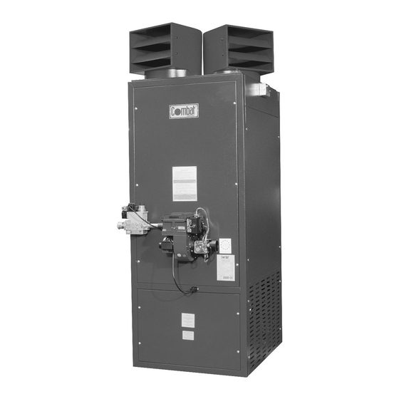
Combat
Warm Air Cabinet
& High-Flow Heaters
Installation, Commissioning,
Service & User Instructions
OIL FIRED: POP, POPH and
Models 015 to 0100
GAS FIRED: PGP, PGPH and
PGP /H/M versions
Models 015 to PGP 0100
Please take time to read and understand these
instructions prior to any installation. Installer must
give a copyof this manual to the user/owner.
Owner/User
Keep this manual in a safe place close to the heater
to provide your serviceman with information should it
become necessary.
Roberts-Gordon Europe Ltd.
Oxford Street
Bilston, West Midlands WV14 7EG UK
Telephone: +44 (0)1902 494425
Fax: +44 (0)1902 403200
email: uksales@rg-inc.com
www.combat.co.uk
www.rg-inc.com
POP /H versions
Installer
X523F 02/03
®
Advertisement
Table of Contents

Related Manuals for Roberts Gorden HF 30 v4

![Heater Roberts Gorden Combat UHA[X][S] 100 Installation & Operation Manual](https://static-data2.manualslib.com/product-images/bdb/141375/60x60/roberts-gorden-combat-uha-x-s-100-heater.jpg)


Summary of Contents for Roberts Gorden HF 30 v4
- Page 1 FOR YOUR SAFETY Combat If you smell gas: 1. Open windows. 2. DO NOT try to light any appliance. ® 3. DO NOT use electrical switches. 4. DO NOT use any telephone in your building. 5. Leave the building. 6. Immediately call your local gas supplier after leaving the building.
- Page 3 CABINET HEATER 2H 3P © 2003...
- Page 4 CABINET HEATER Contents...
-
Page 5: General Specification
CABINET HEATER Section 1. General Specification General Information - Standard Models... - Page 6 CABINET HEATER Air Diffuser Heads Fan/Limit Thermostat Flue Flue Spigot (female) Heat Exchanger Rear Pressure Relief Stainless Steel Combustion Chamber Double Skin Panels Burner Tube (for mounting the 'packaged' burner) Electrical Connections Lower Front Panel Main Fan Assembly (Direct Drive on Models 15 - 50, Belt Dive on Models 60 -100)
- Page 7 CABINET HEATER Basic Information - High Flow (HF) Models 1.2.1 Introduction 1.2.2 Electrical Supply 1.2.3 Controls 1.2.4 Fan Operation...
- Page 8 CABINET HEATER Heater Operation (On/Off) Note: 1.2.1 Heater Operation (High/Low) 1.2.2 Heater Operation (Fully Modulating)
-
Page 9: Technical Data
CABINET HEATER Section 2. Technical Data Table 2.1 General Data All Standard Models PGP and POP and All Versions for High/Low or Modulating Burners... - Page 10 CABINET HEATER Dimensions - All Models PGP and POP Dimensions of outlet spigots - Standard Cabinet Heaters 015/020/030 060/070/080 0100 Air Outlet Spigot Dimensions - Standard Cabinet Heaters...
- Page 11 CABINET HEATER Table 2.2 General Data - High Flow Cabinet Heaters Model Num ber HF 30 v4 HF 30 v5 HF 30 v6 HF 40 v1 HF 40 v2 HF 40 v3 HF 50 v1 HF 50 v2 HF 50 v3...
- Page 12 CABINET HEATER Table 2.3 Oil Fired Burner Data (Ecoflam Burner) Burner Reference "G" M ode l POP 015 POP 020 POP 030 POP 040 POP 050 POP 060 POP 070 POP 080 POP 0100 He at Input (gr os s ) 73.6 109.7 146.2...
- Page 13 CABINET HEATER Table 2.4 Ecoflam ON/OFF Natural Gas (G20) Dungs Valve, Burner Reference C Data for all versions "H" horizontal, "HF" high flow Gas rates corrected to standard conditions 1013.25 mbar 15°C INLET PRESSURE 20 m ba r (Minim um 17 m ba r, Ma x im um 25 m ba r) M ODEL PGP 015 PGP 020 PGP 030 PGP 040 PGP 050 PGP 060 PGP 070 PGP 080 PGP 0100 Gross heat input...
- Page 14 CABINET HEATER Table 2.5 Ecoflam ON/OFF LPG (G31) with Dungs Valve, Burner Reference C Data for all versions "H" horizontal, "HF" high flow Gas rates corrected to standard conditions 1013.25 mbar 15°C INLET PRESSURE 37 mbar (MINIMUM 25 mbar , MAXIMUM 45 mbar) MODEL PGP 015 PGP 020 PGP 030 PGP 040 PGP 050 PGP 060 PGP 070 PGP 080 PGP 0100 Gross heat Input...
- Page 15 CABINET HEATER Table 2.6 Ecoflam HIGH/LOW or MODULATING Burner with Dungs Valve, Burner Reference "H" Natural Gas G20 Data for all versions "H" horizontal, "HF" high flow Gas rates corrected to standard conditions 1013.25 mbar 15°C ECOFLAM HIGH/LOW GAS BURNER WITH DUNGS GAS VALVES FOR NATURAL GAS G20 INLET PRESSURE 20 mbar (minimum 17mbar maximum 25mbar) MODEL PGP 015 PGP 020 PGP 030 PGP 040 PGP 050 PGP 060 PGP 070 PGP 080 PGP 0100...
- Page 16 CABINET HEATER Table 2.7 Ecoflam HIGH/LOW or MODULATING Burner with Dungs Valve Burner Reference "H" L.P.G. G31 Data for all versions "H" horizontal, "HF" high flow Gas rates corrected to standard conditions 1013.25 mbar 15°C INLET PRESSURE 37 m bar (minimum 25m bar, maximum 45mbar) M ODEL PGP 015 PGP 020...
-
Page 17: Operating Sequence
CABINET HEATER Control Box - Oil Fired Heaters High /Low oil burners although following the general sequence as described below also have extra functional stages related to air damper positions. Refer to burner manufacturers instructions for further detail. 2.2.1 2.2.2 Operating Sequence Fig. - Page 18 CABINET HEATER 2.2.3 Sequence of Events 2.2.4 Fault Conditions Control Box - Gas Fired Heaters High /Low and Modulating burners although following the general sequence as described below also have extra functional stages related to air damper positions. Refer to burner manufacturers instructions for further detail. Ecoflam gas burner have only one pressure switch which is configured to cover both available combustion air and reaction to increases in combustion chamber pressure.
- Page 19 CABINET HEATER Fig 2.2 Gas Fired Heater Control Box Sequence 2.3.3 Air Pressure Switch Contacts 2.3.4 Purge 2.3.5 Electric Ignition ON 2.3.6 Start Gas Valve (Main gas for models 015 to 030) 2.3.7 Electric Ignition OFF...
-
Page 20: Combination Fan/Limit Thermostat
CABINET HEATER 2.3.8 Main Gas Valve (For models above 030) 2.3.9 Fault Conditions Honeywell Combination Fan/Limit Thermostat Fig. 2.3 Combination Fan/Limit Thermostat... -
Page 21: Motor Starter And Thermal Overload
CABINET HEATER Motor Starter and Thermal Overload Burners Fig. 2.4 Motor Starter (Models 040 - 0100) and Thermal Overload (Models 060- 0100 only) Gas Valves Used with All Burners 2.7.1 Dungs Combination Gas Valves... - Page 22 CABINET HEATER 2.7.1.1 Start Gas Valves 2.7.1.2 Main Gas Valves Note: For Ecoflam High/Low or Modulating burners then the Dungs gas valve has extra features as it is an air/gas ratio control valve.Please refer to the manufacturers instructions regarding the setting of these controls. 2.7.1.3 Throughput Adjuster 2.7.1.4...
- Page 23 CABINET HEATER Models 015 to 030 - all types of valve Models 040 to 0100 - all types of valve Automatic TO BURNER TO BURNER Burner Regulator gas valves flange Union Automatic Automatic gas valve & gas valve regulator INLET INLET Note orifice plate Automatic...
- Page 24 CABINET HEATER Fan Data - High Flow Cabinet Heaters air flow v static pressure air flow v fan motor current Fig 2.7 Air Flow v Static Pressure & Motor Current - HF30 v4 Graph Air Flow v Static Pressure & Motor Current HF30 v 4 HF 11 with 2.2 kW motor and 85mm pulley fan pulley 180 mm.
- Page 25 CABINET HEATER Fig 2.8 Air Flow v Static Pressure & Motor Current - HF30 v5 Graph Air Flow v Static Pressure & Motor Current HF12 30 V 5 with 4 kW motor and 106mm pulley fan pulley 180 mm. Fan 457-486 ( Based on Model 30 in 50 cabinet ) Air Flow m Air flow v static pressure :...
- Page 26 CABINET HEATER Fig 2.10 Air Flow v Static Pressure & Motor Current - HF40 v1 Graph Graph of Air Flow v Static Pressure and Current. Model HF40 v1 with 2.2kW motor and 95mm pulley. Fan pulley 180mm. Air Flow m /sec Air flow v Static Pressure Air Flow v Motor Current...
- Page 27 CABINET HEATER Fig 2.12 Air Flow v Static Pressure & Motor Current - HF40 v3 Graph Graph of air flow v staic pressure and current for model HF40 v3 with 5.5kW motor with 140mm pulley. Fan pulley 200mm 12.5 11.5 10.5 Air Flow m /sec...
- Page 28 CABINET HEATER Fig 2.14 Air Flow v Static Pressure & Motor Current - HF50 v2 Graph Graph of air flow v staic pressure and current for model HF50 v2with 5.5kW motor with 112mm pulley. Fan pulley 180mm 11.5 10.5 Air Flow m /sec Air Flow v Static pressure : Air Flow v Motor Current...
- Page 29 CABINET HEATER Fig 2.16 Air Flow v Static Pressure & Motor Current - HF50 v4 Graph Graph of air flow v staic pressure and current for model HF50 v4with HF10 7.5kW motor with 140mm pulley. Fan pulley 200mm 16.5 15.5 14.5 13.5 12.5...
-
Page 30: Installation Requirements
CABINET HEATER Section 3. Installation Requirements Required Standards CONSULT BS 6230 FOR FURTHER INFORMATION ON HAZARDOUS AREAS... - Page 31 CABINET HEATER Terminal Lead Roof Cravat Plate 1000mm minimum Guy wires (where flue extends more than 2m above roof) Air distribution heads Flue See text for spacing from Building ventilation walls Electrical supply Gas service cock via isolator Navy union Terminal Lead Roof Cravat...
- Page 32 CABINET HEATER Location of the Heater 3.2.1 Clearances Air Supply (Plant Rooms)
-
Page 33: Building Ventilation
CABINET HEATER 3.3.1 Return Air Ducting Note: Building Ventilation... -
Page 34: Section 4. Installation Of The Heater
CABINET HEATER Section 4. Installation of the Heater Flue... -
Page 35: Electrical Supply
CABINET HEATER Electrical Supply Remote Controls 4.3.1 Individual Controls Siting of Thermostats or Temperature Sensors... - Page 36 CABINET HEATER 4.3.1.1 Controls for High/ Low Burner Operation 4.3.1.2 Controls for Fully Modulating Burners...
-
Page 37: Fuel Oil Supply
CABINET HEATER Fuel Oil Supply 4.4.1 Fuel Storage Tank 4.4.2 Fuel Pipes 4.4.3 Gravity Feed System 4.4.4 B. M. Oil Lifter 4.4.5 Pressurised Systems... - Page 38 CABINET HEATER Total Suction Length in Feet 8mm ( ") O.D. Copper Tube 33ft 65ft 99ft 132ft 165ft 240V Oil Lifter Lift in Feet Lift in Metres Oil Heater Technical data Maximum lift....8 metres Air Vent Filler Pipe Maximum capacity..20 litres/hr Actual capactity..
-
Page 39: Gas Supply
CABINET HEATER Gas Supply General Natural Gas L.P.G. -
Page 40: Commissioning The Heater
CABINET HEATER Section 5. Commissioning the Heater Note: Note: 5.1.1 Pre Commission Checks - All Heaters 5.1.1.2 Electrical Tests 5.1.1.3 Earth Continuity Check... - Page 41 CABINET HEATER 5.1.1.4 Polarity Test - Single phase Note: 5.1.1.5 Polarity Test - Three Phase 1, 2 5.1.1.6 Fan Rotation Check 5.1.2 Electrical Settings 5.1.2.1 Combination Fan/Limit Thermostat Settings Check 5.1.2.2 Fan Motor Overload Check...
-
Page 42: Commissioning The Burner - Oil Heaters
CABINET HEATER Commissioning the Burner - OIL HEATERS 5.2.1 5.2.2 Preparation of Test for Burner Pressure 5.2.3 Switching On Note: Note:... - Page 43 CABINET HEATER 5.2.4 Adjust Burner Oil Pressure 5.2.5 Set Combustion Air 5.2.6 Completion 5.2.7 Hand Over...
- Page 44 CABINET HEATER Commissioning the Burner - GAS HEATERS 5.3.1 Preparation of the Burner 5.3.2 Carry Out A Dry Run 5.3.3 Switching On Note:...
-
Page 45: Initial Setting
CABINET HEATER 5.3.4 Fire the Burner for Dungs Combination Gas Valves 5.3.5 Initial Setting Note: 5.3.6 Set Gas Rate Note: 5.3.7 Set Combustion Air - All Gas Valve Types... - Page 46 CABINET HEATER 5.3.9 Set Air Pressure Switch Note: 5.3.10 Completion 5.3.11 Hand Over...
-
Page 47: Wiring Diagrams
CABINET HEATER Section 6. Wiring Diagrams Fig 6.1 As Wired Diagram for Models 015 to 030 - Floor Standing... - Page 48 CABINET HEATER Fig 6.2 As Wired Diagram for Models 015 to 030 - Horizontal Mounting...
- Page 49 CABINET HEATER Fig 6.3 As Wired Diagram for Models 040 and 050 - Floor Standing...
- Page 50 CABINET HEATER Fig 6.4 As Wired Diagram for Models 040 & 050 - Horizontal Mounting...
- Page 51 CABINET HEATER Fig 6.5 As Wired Diagram for Models 060 to 0100 - Floor Standing...
- Page 52 CABINET HEATER Fig 6.6 As Wired Diagram for Models 060 to 0100 - Horizontal Mounting...
- Page 53 CABINET HEATER Fig 6.9 Final Connections to Ecoflam On/Off Burners, All Models Fig 6.10 Final Connection to Ecoflam High/Low or Modulating Burners, All Models...
- Page 54 CABINET HEATER Fig 6.11 Wiring Diagram for all High Flow Models (except HF 40 v3, HF 50 v2, HF50 v3 and HF50 v4)
- Page 55 CABINET HEATER Fig 6.12 Wiring Diagram for High Flow Models HF40 v3, HF50 v2, HF50 v3 and HF50 v4 Page 55...
- Page 56 CABINET HEATER Star Delta Starters 6.1.1 Lovato Star Delta Starter Fig 6.14 Lovato Star Delta Starter...
-
Page 57: Servicing Instructions
CABINET HEATER Section 7. Servicing Instructions NOTE 1: NOTE 2: NOTE 3: Burner Maintenance Main Fan... -
Page 58: Thermal Insulation
CABINET HEATER Fig. 7.1 Fan Belt Tension Heat Exchanger Maintenance Thermal Insulation... -
Page 59: Removal And Replacement Of Parts
CABINET HEATER Section 8. Removal & Replacement of Parts The Burner and it's Components Direct On Line Main Fan Starter & Thermal Overload Unit (Three Phase Models Only) Control Circuit Fuse (10 or 5 amp 1 ¼" long sand filled) - Page 60 CABINET HEATER Combination Fan/Limit Thermostat (See Fig. 1.1) Main Fan Motor (Three Phase Belt Drive Heaters Only) Main Fan Units Note:...
-
Page 61: Fault Finding Charts
CABINET HEATER Section 9. Fault Finding Charts General - All heaters START Assuming fuel & electrical supplies are ON Is the 'lockout' button on Check control fuse in Does the burner fire ? Repair as necessary the burner alight ? heater has not blown Test burner as in Check external controls... - Page 62 CABINET HEATER Oil Burner Fault Finding (See Burner Manufacturer's Instructions) Check if the control fuse in heater Does the burner fire ? has blown Check supply to burner motor Repair or replace Check control box Does the burner control box 'lockout' Disconnect photo cell and try again Control Box faulty - Replace before 15 seconds ?
- Page 63 CABINET HEATER Gas Burner Fault Finding (see also Burner Manufacturer's Instructions) Is the air pressure switch Does the burner fan run ? See Section 5 for setting at rest (no contact open) Fault lies elsewhere Does 'lockout' occur before the Use 9.3 to check the flame burner has run for 10 secs ? monitoring system...
- Page 64 CABINET HEATER Flame Supervision Systems Connect a DC ammeter in series with the flame monitor Turn on all controls and ensure OIL FIRED supply to burner Is there a stray light entering the burner or is there a flame Is there a current flowing in excess GAS FIRED Repair or replace as necessary of the max.
- Page 65 CABINET HEATER Solenoid Valve Circuit Is there pressure on the outlet of the Is there an electrical supply to the Fault lies elsewhere. valve when the valve valve terminals ? Investigate and correct. should be closed ? Valve faulty. Replace with correct type. Is there an electrical supply to the Fault lies elsewhere.
- Page 66 CABINET HEATER Main Fan Circuit (Single Phase) Main fan will not operate following warm up period of heat exchanger Fault lies elsewhere Re check supply to Check for 230v Press in white button terminals L1 to N at terminals 1 to N of fan/limit thermostat and retest.
- Page 67 CABINET HEATER Main Fan Circuit (Three Phase) Main fan will not operate following warm up period of heat exchanger Fault lies elsewhere Check for 400v three phase supply at main terminals Press in white button of fan/limit Check for 230v at terminals 1 to N Fault lies elsewhere thermostat and retest.
-
Page 68: Section 10. User Instructions
CABINET HEATER Section 10. User Instructions 10.1 Heater Operation (On/Off Operation) Note: 10.1.1 Heater operation (for High/Low or Modulating) - Page 69 CABINET HEATER 10.2.1 Burner Lockout Reset Button 10.2.2 Combination Fan/Limit Thermostat...
- Page 70 CABINET HEATER 10.3 Lighting Instructions (All Heaters) 10.3.1 To Turn the Heater On Note: 10.3.2 To Turn the Heater Off 10.3.2.1 (Short Periods) 10.3.2.2 (Long Periods) 10.3.3 To Restart After Long Shut Off Period...
-
Page 71: Service Information
CABINET HEATER 10.4.1 Simple Fault Finding (All Heater Types) 10.4.2 Simple Fault finding (Oil Fired Heaters) Note: 10.4.3 Simple Fault Finding (Gas Fired Heaters) 10.5 Service Information... - Page 72 CABINET HEATER Note: 10.5.1 Care Of Heater...
-
Page 73: Section 11. Conversion Information
CABINET HEATER Section 11. Conversion Information... -
Page 74: Parts List
CABINET HEATER Section 12. Parts List Roberts-Gordon Contact Numbers... - Page 75 CABINET HEATER GAS HEATER COMMISSIONING DATA SHEET OIL HEATER COMMISSIONING DATA SHEET...
- Page 76 C O N T A C T S SERVICE Tel: 01902 498733 Fax: 01902 401464 SPARES Tel: 01902 499051 Fax: 01902 499042 MAIN SWITCHBOARD Tel: 01902 494425 Fax: 01902 403200 Roberts-Gordon Europe Ltd. Oxford Street, Bilston, West Midlands WV14 7EG Tel: 01902 494425 Fax: 01902 403200 e - m a i l : u k s a l e s @ r g - i n c .
Need help?
Do you have a question about the HF 30 v4 and is the answer not in the manual?
Questions and answers