Table of Contents
Advertisement
Available languages
Available languages
Quick Links
Advertisement
Chapters
Table of Contents

Related Manuals for Gastrodomus SFO500B


Summary of Contents for Gastrodomus SFO500B
- Page 1 MANUALE D'ISTRUZIONE SFOGLIATRICE DA BANCO mod. SFO500B...
-
Page 2: Table Of Contents
INDICE Capitolo 1 Informazioni generali............ 1 Documentazione fornita ............1 Questo manuale ..............1 Proprietà delle informazioni ........... 1 Convenzioni ................. 2 Dati di identificazione del fabbricante ........3 Dati di identificazione della macchina ........3 Dichiarazione CE di conformità ..........3 Garanzia ................ - Page 3 Capitolo 7 Demolizione ..............26 Qualifica dell'operatore ............26 Disattivazione della macchina ..........26 Procedura di disattivazione..........26 Rischi residui dopo la disattivazione ........26 Smaltimento dei rifiuti di apparecchiature elettriche ed elettroniche ............ 27 Capitolo 8 Elenco allegati.............. 28...
-
Page 4: Capitolo 1 Informazioni Generali
Manuale di istruzioni (questo manuale). • Manuale parti di ricambio . Altra documentazione • Schemi elettrici Questo manuale Dati del manuale Manuale di istruzioni SFOGLIATRICE Modello SFO500B • Edizione: 1.0 • Mese e Anno di stampa: Febbraio 2007 Destinatari • Trasportatore. •... -
Page 5: Convenzioni
Capitolo 1 - Informazioni generali. dichiara che le informazioni contenute in questo manuale sono congruenti con le specifiche tecniche e di sicurezza della macchina a cui il manuale si riferisce. Il fabbricante non si assume alcuna responsabilità per danni diretti o indiretti a persone, cose o animali domestici conseguenti all'uso di questo materiale documentale o della macchina in condizioni diverse da quelle previste. -
Page 6: Dati Di Identificazione Del Fabbricante
Capitolo 1 - Informazioni generali. Dati di identificazione del fabbricante __________________________ E mail: ____________________ Dati di identificazione della macchina Tipo:SFOGLIATRICE Modello: SFO500B Matricola:________________ Anno di costruzione:_______________ Fig. 1.1 Targa di identificazione Dichiarazione CE di conformità Vedere Dichiarazione CE di conformità allegata. - Page 7 Capitolo 1 - Informazioni generali. NOTA Nel caso di riparazione sul luogo di installazione della macchina il tagliando di garanzia deve essere esibito al tecnico dell’assistenza e la garanzia è operante solo se lo stesso è compilato in tutte le sue parti. Garanzie particolari saranno espressamente citate nel contratto di vendita.
-
Page 8: Utilizzo Del Manuale
Capitolo 1 - Informazioni generali. Richiesta di interventi in garanzia Modalità Eventuali richieste di parti di ricambio o interventi tecnici in garanzia devono essere segnalate a o al rivenditore autorizzato, immediatamente quando viene riscontrato un difetto che rientra nelle specifiche di Condizioni generali a pag. 3. ATTENZIONE Si consiglia l’uso di ricambi originali. - Page 9 Capitolo 1 - Informazioni generali. Modalità di utilizzo previste La macchina è stata progettata e realizzata per funzionare in ambienti chiusi e protetti dagli agenti atmosferici. Modalità di azionamento previste La macchina è alimentata da energia elettrica, che converte in energia meccanica per gli usi previsti.
- Page 10 Capitolo 1 - Informazioni generali. Struttura della macchina In questa sezione sono descritti gli elementi principali della macchina e la loro funzione all'interno del ciclo di produzione. Parti principali della macchina La macchina è costituita dalla seguenti parti principali: 1. Struttura di base 2.
- Page 11 Capitolo 1 - Informazioni generali. PERICOLO Non indossare indumenti larghi, cravatte, catenine, orologi che possano impigliarsi nelle parti in movimento della macchina. NOTA non si assume alcuna responsabilità per eventuali danni a persone, animali domestici o cose derivanti dal mancato rispetto delle norme di sicurezza e delle raccomandazioni contenute nella documentazione fornita.
-
Page 12: Qualifica Del Personale
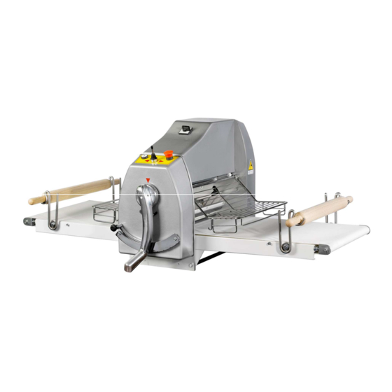
Capitolo 1 - Informazioni generali. 1.11 Qualifica del personale Fase della vita tecnica della macchina Qualifica operatore responsabile Trasporto Trasportatore qualificato che ha recepito i contenuti di: Fig. 1.2 Vista complessiva della macchina, 4.3 Trasporto a pag. 17 di questo manuale. Installazione Un elettricista qualificato e un meccanico qualificato che hanno recepito i contenuti di:... -
Page 13: Protezioni
Capitolo 1 - Informazioni generali. 1.12 Protezioni DEFINIZIONE Sono protezioni tutte le misure di sicurezza che consistono nell'impiego di mezzi tecnici specifici (ripari, dispositivi di sicurezza) per proteggere le persone dai pericoli che non possono essere ragionevolmente limitati attraverso la progettazione. Ripari fissi e mobili •... -
Page 14: Zone Pericolose E Rischi Residui
Capitolo 1 - Informazioni generali. 1.13 Zone pericolose e rischi residui DEFINIZIONE E' zona pericolosa qualsiasi zona all'interno o in prossimità della macchina nella quale una persona è esposta a rischio di lesioni o danni alla salute. Durante alcune procedure di intervento sulla macchina, di volta in volta segnalate in questo manuale, esistono dei rischi residui per l'operatore. -
Page 15: Caratteristiche Della Macchina
Capitolo 2 - Caratteristiche della macchina Caratteristiche della macchina Capitolo 2 Specifiche tecniche Dimensioni e massa della macchina Modello Misura macchina Misura macchina Peso aperta chiusa (kg) SFO500x700B 148x87x60 65x87x73 SFO500x1000B 200x87x60 85x87x99 Altre caratteristiche tecniche Modello Lunghezza Diametro cilindri cilindri Apertura cilindri Misura piani... - Page 16 Capitolo 2 - Caratteristiche della macchina ulteriore distorsione per la somma delle armoniche dalla sesta alla trentesima del 2% sul valore efficace totale tra conduttori in tensione. Squilibrio della tensione di alimentazione trifase Né la componente di sequenza inversa, né la componente di sequenza zero devono essere superiori al 2% della componente di sequenza diretta della tensione.
- Page 17 Capitolo 2 - Caratteristiche della macchina ALTRI PARTICOLARI TECNICI Raschiatore. In caso di spostamento è possibile riposizionare il raschiatore: • estrarre la molla dalla vite di fissaggio • svitare la vite • regolare il raschiatore • rifissare la vite • riagganciare la molla nella vite Il raschiatore...
-
Page 18: Capitolo 3 Interfaccia Operatore
Capitolo 3 - Interfaccia operatore Interfaccia operatore Capitolo 3 Comandi Comandi Simb. Descrizione Funzioni comandate Manipolatore Se viene spostato a DX fa spostare i nastri trasportatori a DX, se spostato a SX fa spostare i nastri trasportatori a SX. Pulsante ON/OFF Se viene azionato la tensione elettrica viene erogata al motore della macchina. -
Page 19: Capitolo 4 Installazione
Capitolo 4 - Installazione Installazione Capitolo 4 NOTA Nella lettura di questo capitolo fare riferimento alle figure dei pannelli di comando riportate nel Capitolo 3 Interfaccia operatore. Zone pericolose e rischi residui durante l’installazione Obbligo di utilizzare i guanti di protezione. Obbligo di utilizzare le scarpe di protezione. -
Page 20: Trasporto
Capitolo 4 - Installazione Trasporto Le indicazioni contenute in questa sezione devono essere rispettate durante le fasi di trasporto della macchina che si possono verificare nelle seguenti situazioni: • Immagazzinamento della macchina. • Prima installazione della macchina. • Ricollocazione della macchina. Condizioni di trasporto La macchina e il suo corredo possono essere trasportati nei seguenti modi, secondo le richieste del cliente:... - Page 21 Capitolo 4 - Installazione abbiano l’etichetta riportante tutti i dati del costruttore e che la portata sia chiaramente leggibile. • Ispezionare le funi prima di utilizzarle: non devono presentare danni, trefoli spezzati o segni di usura. • Non attorcigliare o annodare le funi e seguire le modalità d’uso indicate dal costruttore.
-
Page 22: Operazioni Preliminari
Capitolo 4 - Installazione • Campanella tipo 0-10000. • Staffe di sollevamento. ATTENZIONE Nel caso vi fossero danni, verificatisi durante il trasporto, questi andranno immediatamente comunicati al come pure eventuali differenze che si dovessero riscontrare fra il materiale pervenuto e quanto citato nell’elenco dettagliato del “Packing list”. -
Page 23: Messa In Servizio
Capitolo 4 - Installazione • In prossimità della zona di collocazione devono essere predisposte le fonti di alimentazione di energia, in conformità a Dati di alimentazione a pag. 12. • L'operatore deve circolare senza impedimenti intorno alla macchina. La distanza rispetto alla parete più... -
Page 24: Impianto Elettrico
Capitolo 4 - Installazione Impianto elettrico Fig. 4.2 Posizione dell’impianto elettrico IMPIANTO ELETTRICO Collaudo Prima della consegna la macchina viene collaudata presso il costruttore effettuando le seguenti operazioni: • Regolazione generale della macchina, delle apparecchiature ausiliarie e delle protezioni applicate. •... -
Page 25: Capitolo 5 Uso
Capitolo 5 - Uso Capitolo 5 NOTA Nella lettura di questo capitolo fare riferimento alle figure dei pannelli di comando riportate in Capitolo 3 Interfaccia operatore. Qualifica dell’operatore L'uso della macchina deve essere effettuato esclusivamente da personale addestrato, qualificato e autorizzato, dopo aver studiato e acquisito le informazioni fornite da questo manuale. -
Page 26: Modi Di Funzionamento
Capitolo 5 - Uso Modi di funzionamento La macchina funziona in modo manuale seguendo le istruzioni descritte in Capitolo 5 Uso a pag. 22. Accensione della macchina Procedura di accensione: 1. Ruotare in posizione I l'interruttore-sezionatore sito sul carter motore nel fronte della macchina. -
Page 27: Capitolo 6 Manutenzione
Capitolo 6 - Manutenzione Manutenzione Capitolo 6 PERICOLO Rischi di scosse elettriche e di movimenti intempestivi durante la manutenzione. Isolare la macchina dalle fonti di alimentazione di energia elettrica . Dissipare e/o contenere le energie residue (vedi Capitolo 5 Uso). Manutenzione ordinaria Rientrano nella manutenzione ordinaria tutte quelle operazioni che possono essere eseguite dall'utilizzatore. -
Page 28: Manutenzione Programmata
Capitolo 6 - Manutenzione ATTENZIONE Non impiegare getti d’acqua per la pulizia dei pannelli di comando e dell’armadio elettrico. Attrezzi e prodotti per la pulizia Metodo di pulizia ATTENZIONE Evitare l'uso di solventi che danneggiano la vernice e i materiali sintetici. In particolare, evitare l'uso di benzina, diluente nitro - percloro e trielina. - Page 29 Capitolo 7 - Demolizione Demolizione Capitolo 7 Qualifica dell'operatore Meccanico qualificato che ha recepito i contenuti di Fig. 1.2 Vista complessiva della macchina e Capitolo 7 Demolizione. Disattivazione della macchina Una volta raggiunta la fine della vita tecnica e operativa della macchina, la macchina deve essere disattivata.
- Page 30 Capitolo 7 - Demolizione ATTENZIONE La macchina è realizzata con materiali non biodegradabili. Portare la macchina in un deposito autorizzato per lo smaltimento. Smaltimento dei rifiuti di apparecchiature elettriche ed elettroniche Ai sensi dell'Art. 13 del Decreto legislativo 25 Luglio 2005, n.° 151 "Attuazione delle Direttive 2002/95/CE, 2002/96/CE e 2003/108/CE, relative alla riduzione dell'uso di sostanze pericolose nelle apparecchiature elettriche ed elettroniche , nonchè...
- Page 31 Capitolo 8 - Elenco allegati Elenco allegati Capitolo 8 Allegato 1 Schemi elettrici Allegato 2 Pezzi di ricambio...
- Page 32 Capitolo 8 - Elenco allegati Fig. 8.1 Schema elettrico 1...
- Page 33 Capitolo 8 - Elenco allegati Fig. 8.2 Schema elettrico 2...
- Page 34 Capitolo 8 - Elenco allegati Fig. 8.3 Schema elettrico 3...
- Page 35 Capitolo 8 - Elenco allegati PEZZI DI RICAMBIO Descrizione Descrizione SPALLA DESTRA 59 CUSCINETTO 6005 2RS SPALLA SINISTRA 60 CORONA TENDICATENA PANNELLO DESTRO 61 TIRANTE CATENA PANNELLO SINISTRO 62 DISTANZIALE TIRANTE CATENA FLANGIA 63 BOCCOLA ALBERO PER SOLLEVAMENTO CUSCINETTO 6004 2RS 64 PULEGGIA MOTORE ANELLO SEEGER 65 MOTORE ELETTRICO...
- Page 36 Capitolo 8 - Elenco allegati...
- Page 37 USER MANUAL BENCH PASTRY SHEETER mod. SFO500B...
- Page 38 CONTENTS Chapter 1 General information............1 Documentation provided ............1 This manual ................ 1 Proprietary rights of the information ........1 Conventions ................ 2 Manufacturer identification details ........3 Machine identification details..........3 EC declaration of conformity ..........3 Guarantee................
- Page 39 Chapter 7 Machine scrapping ............26 Qualifications of operator ........... 26 Disconnecting the machine..........26 Disconnection procedure............ 26 Residual risks after machine disconnection ......26 Chapter 8 List of attached documentation ........28...
-
Page 40: Chapter 1 General Information
User Manual (this manual). • Spare Parts Manual . Additional documentation • Electrical wiring diagrams This manual Manual data User Manual SHEETER Model SFO500B • Edition no.: 1.0 • Printed in Month and Year: February 2007 For the use of • Carrier. •... -
Page 41: Conventions
Chapter 1 - General information. The manufacturer reserves the right to introduce technical modifications or improvements both to the documentation and to the machines without prior notice. Modifications and improvements may also concern other machines of the same model described in this manual, but which have a different serial number. -
Page 42: Manufacturer Identification Details
_________________________________________ _________________________________________ _________________________________________ _________________________________________ _________________________________________ _________________________________________ Machine identification details Type:DOUGH SHEETER Model: SFO500B Serial no.:________________ Year of manufacture:_______________ Fig. 1.1 Data plate EC declaration of conformity See EC declaration of conformity attached. Guarantee General conditions 1. This machine (with appropriate serial number) is guaranteed for 12 months after the date of actual delivery. - Page 43 Chapter 1 - General information. 2. The guarantee covers the replacement or repair of the faulty part (component, machine or part of the machine) but does not cover the cost of dismantlement, re-assembly or shipping. 3. The replacement of any part does dot bring about the renewal of the guarantee period for the entire machine, unless the entire machine is replaced.
-
Page 44: Use Of The Manual
Chapter 1 - General information. Claiming under guarantee Method Requests for spare parts or service visits under guarantee must be made to the manufacturer or to your authorised dealer as soon as possible after having encountered the defect which is covered by the General conditions on page 3. -
Page 45: Description Of The Machine
Chapter 1 - General information. 1.10 Description of the machine Intended use Intended operations The machine has been built and designed to sheet dough to the thickness required by the operator. Conditions of intended use The machine has been designed and built to operate in a closed environment, protected from atmospheric agents. - Page 46 Chapter 1 - General information. Machine structure This section describes the main machine components and their function within the production cycle. Main machine components The machine is composed of the following principal components: 1. Base 2. Control Panel. 3. Conveyor Belts. 4.
- Page 47 Chapter 1 - General information. NOTE The manufacturer will not be liable for any damage or injury to persons, animals or things caused by non-observance of the safety rules and/or recommendations given in the documentation supplied.
-
Page 48: Qualifications Of Personnel
Chapter 1 - General information. 1.11 Qualifications of personnel Stage in the technical life of the machine Qualification of operator in charge Transport Qualified carrier informed of: Fig. 1.2 Overall view of machine, 4.3 Transport on page 17 of this manual. Installation Qualified electrician and qualified mechanic informed of : Fig. -
Page 49: Safeguards
Chapter 1 - General information. 1.12 Safeguards DEFINITION Safeguards are any safety measures which involve the application of specific technical mechanisms (guards, safety devices) to protect people from dangers which cannot be made sufficiently harmless through design. Fixed and moveable guards •... -
Page 50: Hazardous Areas And Residual Risks
Chapter 1 - General information. 1.13 Hazardous areas and residual risks DEFINITION A hazardous area is any area inside or in the vicinity of the machine which would constitute a risk for the health and safety of an exposed person. This manual indicates all the procedures during which residual risks for the operator are present. -
Page 51: Chapter 2 Machine Specifications
Chapter 2 - Machine Specifications Machine Specifications Chapter 2 Technical specifications Dimensions and weight of the machine Model Measurement Measurement Weight machine open machine closed (kg) SFO500x700B 148x87x60 65x87x73 SFO500x1000B 200x87x60 85x87x99 Other technical characteristics Model Cylinder Cylinder Cylinder length diameter opening Table... - Page 52 Chapter 2 - Machine Specifications Harmonics The harmonic distortion, for the sum of harmonics from the second to the fifth, should not exceed 10% of the total voltage with effective value between live conductors. A further distortion of 2% for the sum of the harmonics from the sixth to the thirtieth on the total effective value between live conductors is tolerated.
- Page 53 Chapter 2 - Machine Specifications Other Technical Details Scraper. In case of movement it is possible to reposition the scraper: • remove the spring from the fixing screw • unscrew the screw • adjust the scraper • tighten the screw •...
-
Page 54: Chapter 3 Operator Interface
Chapter 3 - Operator Interface Operator Interface Chapter 3 Controls Controls Symbol Description Functions controlled Manipulator when it is moved to the right the conveyor belts shift to the right, when it is moved to the left the conveyor belts shift to the left. ON /OFF button When On is pressed power is supplied to the machine's motor. -
Page 55: Chapter 4 Installation
Chapter 4 - Installation Installation Chapter 4 NOTE When reading this chapter refer to the pictures of the control panels given in Chapter 3 Operator Interface. Hazardous areas and residual risks during installation Protective gloves must be worn. Protective footwear must be worn. Handling area of the packed or unpacked machine. -
Page 56: Transport
Chapter 4 - Installation Transport The instructions given in this section should be carefully followed when transporting the machine. This operation may include the following situations: • Storage of the machine. • Initial installation of the machine. • Re-location of the machine. Transport conditions The machine and its equipment can be transported in the following ways, according to the customer's requirements:... - Page 57 Chapter 4 - Installation • Check that the hoisting cables or ropes are equipped with bell and have the label which contains all the manufacturer's details and that the lifting capacity is clearly stated. • Check the cables or ropes before each lifting operation. Do not use these if they are damaged or worn or have broken strands or wires.
-
Page 58: Preliminary Operations
Chapter 4 - Installation • Hook type 0-10000. • Lifting brackets. BEWAREE If the machine has been damaged during transport, inform the manufacturer immediately. The manufacturer should also be informed if there are differences between the "Packing list" and the goods actually delivered. -
Page 59: Preparation For Start-Up
Chapter 4 - Installation be near the installation site. • Nothing should hinder the free movement of the operator around the machine. The machine should be situated at least 1 metre from the nearest wall or object. • Cabinets should be accessible at all times and the doors should open wide without obstacle. -
Page 60: Electric System
Chapter 4 - Installation Electric system Fig. 4.2 Electric system position ELECTRIC SYSTEM Testing Before delivery the machine is tested at the manufacturer's works where the following operations are carried out: • General setting of the machine, of the auxiliary equipment and of the installed safety devices. -
Page 61: Chapter 5 Machine Operation
Chapter 5 - Machine operation Machine operation Chapter 5 NOTE When reading this chapter refer to the pictures of the control panels given in Chapter 3 Operator Interface. Qualifications of operator The machine should be operated only by trained, qualified and authorised personnel who have read and understood the information contained in this manual. -
Page 62: Operating Modes
Chapter 5 - Machine operation Operating modes The machine operates in manual mode following the instructions described in Chapter 5 Machine operation on page 22 Machine switching on To switch the machine on proceed as follows: 1. Turn the knife-switch situated upstream from the outside power supply cable to position I. Tooling, adjustments and setting up Adjustment warnings 1. -
Page 63: Chapter 6 Maintenance
Chapter 6 - Maintenance Maintenance Chapter 6 DANGER Risk of electric shock and unexpected movements during maintenance. Isolate the machine from electric and hydraulic power sources. Dissipate and/or limit residual energy (see Chapter 5 Machine operation). Routine maintenance Any operation that can be carried out by the user is considered routine maintenance. It includes operations of cleaning, inspection and prevention carried out to ensure safe operation of the machine. -
Page 64: Scheduled Servicing
Chapter 6 - Maintenance Suitable cleaning tools and products Cleaning method BEWAREE Do not use solvents which could damage the paint and the synthetic materials. Avoid especially petrol, nitro-perchlorate thinners and trichloroethane.. Parts to be cleaned Method and tools Painted steel Use warm water and food-friendly degreaser. - Page 65 Chapter 7 - Machine scrapping Machine scrapping Chapter 7 Qualifications of operator Qualified mechanic who has read and understood Fig. 1.2 Overall view of machine e Chapter 7 Machine scrapping. Disconnecting the machine At the end of its technical and working life the machine has to be disconnected. Even though de-commissioning has taken place and the machine is no longer suited to the purpose for which it has been designed and built, it must still be possible to re-cycle the raw materials from which the machine was built.
- Page 66 Chapter 7 - Machine scrapping followed carefully, there are no residual risks after the machine has been disconnected. BEWAREE The materials used for building the machine are non-biodegradable. The machine must therefore be taken to an authorised scrap yard for disposal.
- Page 67 Chapter 8 - List of attached documentation List of attached documentation Chapter 8 Enclosure 1 Wiring diagrams Enclosure 2 Spare parts catalogue...
- Page 68 Chapter 8 - List of attached documentation Fig. 8.1 Wiring diagram 1...
- Page 69 Chapter 8 - List of attached documentation Fig. 8.2 Wiring diagram 2...
- Page 70 Chapter 8 - List of attached documentation Fig. 8.3 Wiring diagram 3...
- Page 71 Chapter 8 - List of attached documentation SPARE PARTS Description Description RIGHT SHOULDER 59 BEARING 6005 2RS LEFT SHOULDER 60 CHAIN TIGHTENER CROWN GEAR RIGHT PANEL 61 CHAIN TIE ROD LEFT PANEL 62 CHAIN TIE ROD SPACER FLANGE 63 LIFTING SHAFT BUSH BEARING 6004 2RS 64 MOTOR PULLEY SEEGER RING...
- Page 72 Chapter 8 - List of attached documentation...
- Page 73 � ASTRODOMUS...
Need help?
Do you have a question about the SFO500B and is the answer not in the manual?
Questions and answers