
Related Manuals for IDTECH SmartPIN L80


Summary of Contents for IDTECH SmartPIN L80
- Page 1 SmartPIN L80 User Manual 80180501-001 Rev. A 10 November 2021 ID TECH 10721 Walker Street Cypress, CA 90630 Voice: (714) 761-6368 Fax: (714) 761-8880...
- Page 2 Copyright 2021© by ID TECH, Inc. All rights reserved. The information contained herein is provided to the user as a convenience. While every effort has been made to ensure accuracy, ID TECH is not responsible for damages that might occur because of errors or omissions, including any loss of profit or other commercial damage, nor for any infringements or patents or other rights of third parties that may result from this information’s use.
- Page 3 Revision History Date Changes 11/10/2021 • Initial Release Page | 3...
-
Page 4: Table Of Contents
Table of Contents 1. OVERVIEW ....................................6 1.1. Features .................................... 6 1.2. Agency Approvals ................................7 2. SPECIFICATIONS ..................................8 2.1. LED Specifications ................................8 2.2. Keypad Specifications ..............................9 2.1. L80 Dimensions................................10 3. BASE FUNCTIONALITY ................................11 3.1. PIN Pad Functions.................................11 3.2. - Page 5 6.2.13. Set Enter Sleep Mode Time......................................32 6.3. Bootloader Commands ..............................33 6.3.1. Enter into Bootloader..........................................33 6.4. Other PIN Pad Group (Task) Commands........................34 6.4.1. Get Encrypted PIN............................................34 6.4.2. Get Numeric with Display Message .................................... 36 6.4.3. Display Message and Get Numeric Key................................... 38 6.4.4.
-
Page 6: Overview
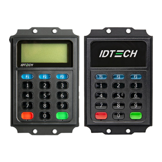
PIN and/or manual-entry capability. The device’s 15-key layout and optional built-in LCD make it ideal for kiosks and other unattended applications. For development of applications that communicate with the SmartPIN L80, please ask your ID TECH representative about the ID TECH Universal SDK for L80 (Windows), which contains libraries (DLLs), C# source code, a demo app, and documentation for a C# API on Windows. -
Page 7: Agency Approvals
1.2. Agency Approvals FCC Class A • • RoHS • REACH • VCCI • Page | 7... -
Page 8: Specifications
2. Specifications Hardware Interface USB-HID, RS-232 (serial) USB power supplied by host cable USB-HID mode or AC-adapter in Power Supply RS-232 mode Power Consumption Run mode: <200 mA Sleep mode: 2.5 mA Stop mode: 0.5 mA Physical Length 93.5mm 60mm Width 26.4mm Depth... -
Page 9: Keypad Specifications
2.2. Keypad Specifications Color: Number keys are Black C; Function keys (A) are blue Pantone 7700C; Cancel key (B) is red Pantone 032U; Enter key (C) is green Pantone 355U. Layout: Alphanumeric characters printed on the keys. Tactile identifier on the numeral key 5 (D) meets ADA standards. -
Page 10: L80 Dimensions
2.1. L80 Dimensions Page | 10... -
Page 11: Base Functionality
3. Base Functionality The section below describes the SmartPIN L80’s base functionality. 3.1. PIN Pad Functions PIN MK/SK, DUKPT Key Management. • TDES Encryption/AES encryption. • Compact key layout (3 x 5 layout: 0-9 numerical keys, Cancel, Enter, F1, F2, F3). -
Page 12: Low-Power Modes
3.3. Low-Power Modes The L80 features two low-power modes: Sleep Mode and Stop Mode. 3.3.1. Sleep Mode While using the RS232 interface, Sleep Mode is controlled by a timeout after the L80 is idle for a specified time (default is 120s). While using the USB interface, Sleep Mode is controlled by the USB suspend and resume signals. -
Page 13: Installation And Pairing
The following sections describe how to install and mount the L80, as well as how to pair it with a VP5300 or VP5300M reader. 4.1. Equipment Checklist Verify that you have the following hardware for installing the SmartPIN L80: SmartPIN L80 (P/N 80180003-51) •... -
Page 14: Mounting
6. Observe the LCD, LED, and buzzer, and make sure the device is not in tamper mode. If the device is in tamper mode, the device behavior is: SmartPIN L80 w/o LCD SmartPIN L80 w/ LCD Fatal Error Buzzer Buzzing noise Buzzing noise 4.3. -
Page 15: Pin Pad And Msr Pairing Solution
4.4. PIN Pad and MSR Pairing Solution The steps below describe how to pair an L80 and MSR device. 4.4.1. Step 1: Send the Send MSR KSN for Pairing to the L80 First, use the Send MSR KSN for Pairing command to send the Pairing MSR KSN from MSR device to the L80. -
Page 16: Step 2: Send The Mac To The L80
4.4.2. Step 2: Send the MAC to the L80 Use the Send MAC for Pairing command to pass the MAC to the L80. Command Name: Send MAC for Pairing Command Body: 75 46 10 01 + [20 bytes ASCII KSN] + [6 bytes ASCII MAC] Command Example Command Body High... - Page 17 4. Under Device, select Update Device Firmware, then click Execute Command. 5. Navigate to and select the L80 firmware you downloaded earlier and click Open. 6. The L80 will reboot and enter the bootloader, at which point the SDK demo begins updating the device.
-
Page 18: Lcd, Beeper, And Led States
5. LCD, Beeper, and LED States The section below describes the L80’s LCD screen and LED and beeper behaviors. 5.1. LCD and Beeper State Diagram • PK: Public Key (Manufacture Key) • FK: Firmware Key • NK: Numeric Key CV: Check Value •... -
Page 19: Other Lcd State For Pin Function
Device State Definition LCD Display Message Beeper State LED auxiliary indicator Activation2 Activation Ready Not beeping • If not set user PK, FK, SCV, passwords: Blink NK, and DTV Yellow loaded successfully • If set user passwords: Steady Yellow At least DUKPT Key •... -
Page 20: Tamper And Failed Self-Check Indicators
Beep short tone 3 times 5.4. Tamper and Failed Self-Check Indicators The SmartPIN L80 displays the following indicators when it has been tampered or has any of the other following internal issues, such as an expired certificate, missing key, or similar fault discovered during a self-check. -
Page 21: Firmware Commands
6. Firmware Commands The following sections list the L80’s firmware commands. 6.1. NGA Command and Response Format The L80 uses NGA protocol commands and responses in general communication. The format is: <STX><Len_Low><Len_High><Command Body/Response Body/Notification Body><CheckLRC><CheckSUM><ETX> Where: • <STX> is 0x02 and <ETX> is 0x03 •... -
Page 22: General Firmware Commands
49 4E 20 4C 31 30 30 20 46 69 72 6D 77 61 72 65 20 56 31 2E 30 30 3A 74 03 <STX><length byte low><length byte high><ACK>ID TECH SmartPIN L80 Firmware V1.00 <LRC><SUM><ETX> 6.2.2. Get Internal Firmware Version The Get Internal Firmware Version command retrieves the internal version number for the L80’s... -
Page 23: Get Serial Number
6.2.3. Get Serial Number The Get Serial Number command retrieves the L80’s serial number. Command Body: 78 46 02 Command Example Command Body High 78 46 01 Output Hex String: 02 03 00 78 46 02 3C C0 03 Response Body: 06 + 10 bytes ASCII code Serial Number 15 62 00: No Serial Number Response Example... -
Page 24: Get Model Status
6.2.4. Get Model Status The Get Model Status command retrieves the L80’s current model status. Command Body: 78 46 20 Command Example Command Body High 78 46 20 Output Hex String: 02 03 00 78 46 20 1E DE 03 Response Body: 06 + Model Status Response Example Response Body... -
Page 25: Get Status For Key
6.2.6. Get Status for Key The Get Status for Key command retrieves the status for a specified key. Command Body: 78 46 25 Command Example Command Body High 78 46 25 Output Hex String: 02 03 00 78 46 25 1B E3 03 Response Body: 06 <2-byte Block Length><KeyStatusBlock1><[KeyStatusBlock2]>... - Page 26 Response Example Response Body High 06 <Block Length Low><Block Length High><KeyStatusBlock1> <[KeyStatusBlock2]> … <[KeyStatusBlockN]> Response Hex String Example: If one device supports PIN DUKPT Key, 12 PIN Master Key (Slot is 0-11), 1 PIN Session Key, PCI Pairing BDK Key (include HSM KEK DUKPT Key). The response: 06 18 00 <00 00 00 00>...
-
Page 27: Get Key Status
Key Name Key Index and Key Name Desjardins PIN Session Key 0x41 <key slot>: 2 bytes. Range is 0: 9999 (If key has not Slot, the value is 0x00 0x00, if key slot is • 1000, the value is 0x03 0xE8) <key status>: 1 byte: •... - Page 28 Where: Status Note 0: None. PIN DUKPT Key 1: Exist 0xFF: STOP 0: None PIN Master Key 1: At least Exist a Master 0: None. Standard PIN Session Key 1: Exist 0: None. Desjardins PIN Session Key 1: Exist 0: None. Does not support this key.
-
Page 29: Set Remote Key Injection Timeout
6.2.8. Set Remote Key Injection Timeout The Set Remote Key Injection Timeout command sets the L80’s timeout for RKI. Command Body: 78 53 01 01 02 <Timeout_H><Timeout_L> Command Example Command Body High 78 53 01 01 02 00 C0 Output Hex String: 02 07 00 78 53 01 01 02 00 C0 E9 8F 03 In this example, the timing value is 0x00C0 or 192 (decimal) seconds. -
Page 30: Set Date & Time
6.2.10. Set Date & Time The Set Date & Time command sets the L80’s date and time. Command Body: 78 53 01 50 06 <Date Time> Command Example Command Body High 78 53 01 50 06 Output Hex String (example): 02 0B 00 78 53 01 50 06 16 05 20 10 30 56 39 F3 Where: <Data Time>... -
Page 31: Enter Stop Mode
Response Example Response Body High 06 78 01 50 06 16 05 10 13 16 19 Output Hex String: 02 0B 00 06 78 01 50 06 16 05 10 13 16 19 36 42 03 Which is STX, 2 length bytes, ACK + 78 01 50 06 + <Data Time> Where: <Data Time>... -
Page 32: Set Enter Sleep Mode Time
6.2.13. Set Enter Sleep Mode Time The Set Enter Sleep Mode Time command sets the L80’s timeout period (the period after which the L80, if idle, goes to sleep); the default is 120 seconds. Command Body: 78 46 71 <TimeH><TimeL> Command Example Command Body High... -
Page 33: Bootloader Commands
6.3. Bootloader Commands When the L80 enters the Bootloader, the device is in the “Waiting State” with “Bootloader…” in Line 0 of the LCD display. In this state, the device can only receive the Get Version command. The expected response is the Bootloader version. The L80 can receive the Get Version command and all Data Blocks commands: If the L80 successfully receives Get Version command, it respond with “Bootloader”... -
Page 34: Other Pin Pad Group (Task) Commands
6.4. Other PIN Pad Group (Task) Commands The section below details commands related to the L80’s PIN pad. 6.4.1. Get Encrypted PIN The Get Encrypted PIN command retrieves the encrypted PIN from the L80. Command Body: 75 46 07 <KeyType><PAN (Account#)><LCD len><LCD Command format> Command Example Command Body High... - Page 35 Note: If Get Encrypted PIN using Plaintext PAN: • If the Plaintext PAN is an error, the response is 15 07 02 If Get Encrypted PIN using encrypted PAN: • If there is no BDK of the Pairing MSR Key, the response is 15 07 00 If there is a BDK of the Pairing MSR Key, but pairing is not implemented successfully, the response is 15 07 01 If pairing is implemented successfully, but the Encrypted PAN is an error, the response 15 07 02...
-
Page 36: Get Numeric With Display Message
6.4.2. Get Numeric with Display Message The Get Numeric with Display Message command gets the numbers entered on the PIN pad and displays them on the LCD. Command Body: 75 46 08 & <Len><Flag><Display Message String><256 bytes Signature> Command Example Command Body High 75 46 08 08 00 41 42 43 44 45 46 47 48 83... - Page 37 Where: <Len>: 1 byte, is the length of Display Message String <Flag>: 1 byte, is Display Option of Line2 Bit0 = 0: When a numeric key is pressed, the L80 increases the display with that number on the LCD if the Total numeric length is less than 16 When the Backspace key is pressed, the L80 decreases the display with the last number on the LCD if the Total numeric length is not 0.
-
Page 38: Display Message And Get Numeric Key
When the Cancel key is pressed, the L80 displays the cursor on the LCD if the Total numeric • length is not 0, or the L80 quits the work state. When the Cancel Command is sent, the L80 quits the work state. •... - Page 39 Output Hex String: 02 0F 01 75 46 22 00 0C 04 08 41 42 43 44 45 46 47 48 2B 9A B6 F5 A9 A1 46 33 1E E9 BF A2 19 F7 88 85 CB B3 EF B2 E5 6A 8B EA D3 BA 7E BC 42 05 41 F2 93 B1 5C D2 3A 50 91 D8 61 79 40 46 36 80 CC 46 2C EB D3 04 7C 60 3D 0B 7B 9C 0C 95 CD AB D4 D5 2F 27 A4 CA 29 4F 25 45 6C E0 18 E7 24 BC F0 B8 D0 18 76 6F 87 1D 55 E1...
-
Page 40: Display Message And Get Amount
When the Cancel key is pressed, the L80 displays the cursor on the LCD if the Total numeric • length is not 0, or the L80 quits the work state. When the Cancel Command is sent, the L80 quits the work state. •... - Page 41 Output Hex String: 02 0F 01 75 46 23 00 0C 04 08 41 42 43 44 45 46 47 48 2B 9A B6 F5 A9 A1 46 33 1E E9 BF A2 19 F7 88 85 CB B3 EF B2 E5 6A 8B EA D3 BA 7E BC 42 05 41 F2 93 B1 5C D2 3A 50 91 D8 61 79 40 46 36 80 CC 46 2C EB D3 04 7C 60 3D 0B 7B 9C 0C 95 CD AB D4 D5 2F 27 A4 CA 29 4F 25 45 6C E0 18 E7 24 BC F0 B8 D0 18 76 6F 87 1D 55 E1...
-
Page 42: Get Function Key
6.4.5. Get Function Key The Get Function Key command retrieves the function key pressed on the PIN pad. Command Body: 75 46 0B Command Example Command Body High 75 46 0B Output Hex String: 02 03 00 75 46 0B 38 C6 03 Response Body: 06 + 1 byte ASCII code Func Key or 2 bytes ASCII code Func Key. -
Page 43: Set Pin Len
6.4.7. Set PIN Len The Set PIN Len command sets the L80’s expected PIN length. Command Body: 75 53 01 01 02 MinLen MaxLen Command Example Command Body High 75 53 01 01 02 MinLen MaxLen Output Hex String: 02 07 00 75 53 01 01 02 04 0A 2A DA 03 MinLen need be 4~12 MaxLen need be 4~12 MinLen need be same or less than MaxLen Response Body: 06... -
Page 44: Set Numeric Len
6.4.9. Set Numeric Len The Set Numeric Len command sets the L80’s expected numeric length. Command Body: 75 53 01 02 02 MinLen MaxLen Command Example Command Body High 75 52 01 02 02< MinLen><MaxLen> Output Hex String: 02 07 00 75 52 01 02 02 08 10 3E E4 03 MinLen need be 1~16 MaxLen need be 1~16 MinLen need be same or less than MaxLen Response Body: 06... -
Page 45: Default Pin Pad Group All Setting
6.4.11. Default PIN Pad Group All Setting The Default PIN Pad Group All Setting command resets the L80’s PIN pad group settings back to the default configuration. Command Body: 75 53 00 Command Example Command Body High 75 53 00 Output Hex String: 02 03 00 75 53 00 26 C8 03 Response Body: 06 The following settings will be reset to their default values:... - Page 46 Command Example Command Body High 75 46 06 07 Output Hex String: 02 04 00 75 46 06 07 32 C8 03 Where: Para is 1 byte. Bit0 User does not input CVV data. User inputs CVV data. Bit1 User does not input ADR data. User inputs ADR data. Bit2 User does not input ZIP data.
-
Page 47: Real Time Key Press Support
If the user presses Cancel, the L80 displays a cursor on the LCD if the total PIN length is not 0, • or L80 quits the work state. When the Cancel command is sent or the user presses Cancel, the L80 quits the work state. •... - Page 48 Bits Description bit 1 0: When the Get PIN from CR command is executed, the L80 will not output any key event when a key pressed (a requirement for the Spectrum Pro/VP5300) and outputs the encrypted PIN block when the Enter Key is pressed.
-
Page 49: Beeper Control Commands
6.5. Beeper Control commands The section below details commands that control the L80’s beeper. 6.5.1. Open / Close Beeper The Open / Close Beeper command turns the beeper on and off. Command Body: 75 46 01 01 <On/Off> Command Example Command Body High 75 46 01 01 01... -
Page 50: Lcd Group (Task) Commands
<Dur3><Dur4> is the first and second nibble for the second byte of Duration. • If the Duration is 200 (0x00C8), <Fre1><Fre2><Fre3><Fre4> will be 0x43 0x38 0x30 0x30. • Duration need be more than 16ms and less than 65535 ms. Response: If the Beeper is Off, the response 15. -
Page 51: Save Prompt Display
6.6.2. Save Prompt Display The Save Prompt Display command saves a specified prompt (0-9) and a 16-character message. Command Body: 8A 46 24 <Prompt><Message> Where: <Prompt>: Prompt number 0-9 • <Message>: Display message 16 char MAX ((ASCII Code: 0x20~0x7F)) • Command Example Command Body High... -
Page 52: Display Prompt
30 30 20 52 65 61 64 79 D2 F6 03 Where: <Line>: Display line number 0 or 1 • <1~16 Message >: Message (ASCII Code: 0x20~0x7F) • The example above sets the message "SmartPIN L80 Ready" Response Body: 06 Page | 52... -
Page 53: Default Lcd Group All Setting
6.6.5. Default LCD Group All Setting The Default LCD Group All Setting command resets all the L80’s LCD settings to their defaults. Command Body: 8A 53 00 Command Example Command Body High 8A 53 00 Output Hex String: 02 03 00 8A 53 00 D9 DD 03 Response Body: 06 Default values: Function Name... -
Page 54: Set Back Light Of Lcd On/Off
6.6.7. Set Back Light of LCD On/Off The Set Back Light of LCD On/Off command controls the L80’s LCD backlight. Command Body: 8A 53 01 04 01 <Control> Command Example Command Body High 8A 53 01 04 01 01 Output Hex String: 02 06 00 8A 53 01 04 01 01 DC E4 03 Where: <Control>: 0: OFF... -
Page 55: Rs-232 Task Commands
6.7. RS-232 Task Commands The section below details commands that control the L80’s RS-232 port. 6.7.1. Set BaudRate The Set BaudRate command sets the L80’s BaudRate. Command Body: 70 53 01 41 01 <ASCIIChar> Command Example Command Body High 70 52 01 41 01 <Speed> Output Hex String: 02 06 00 70 53 01 41 01 36 54 3C 03 This example shows Speed as 0x36, the code for 19200 (see table below). -
Page 56: Get Baudrate
6.7.2. Get BaudRate The Get BaudRate command retrieves the L80’s current BaudRate. Command Body: 70 52 01 41 Command Example Command Body High 70 52 01 41 Output Hex String: 02 04 00 70 52 01 41 62 04 03 Response Body: 06 70 41 01 <ASCIIChar>... -
Page 57: Set Stopbits
6.7.3. Set StopBits The Set StopBits command sets the L80’s StopBits. Command Body: 70 53 01 45 01 ASCIIChar Command Example Command Body High 70 53 01 45 01 31 Output Hex String: 02 06 00 70 53 01 45 01 31 57 3B 03 StopBits ASCIIChar 1 0x31 2 0x32... -
Page 58: Error Codes
7. Error Codes Error Code Definition 0x0100 Log is full 0x0400 Related Key was not loaded 0x0500 Key Same 0x0501 Key is all zero 0x0502 TR-31 format error 0x0700 No BDK of Pairing MSR Key 0x0701 Have BDK of Pairing MSR Key, Not Pairing with MSR (No PAN Encryption Key) 0x0702 PAN is Error 0x0703... - Page 59 Error Code Definition 0x7200 MKSK Suspend or press passwords Error Suspend 0x7300 PIN/MSR/ICC/ RKI-KEK (Admin DUKPT Key) is STOP (21 bit 1) 0x7400 Device is Busy 0x7500 Device is in diagnose mode 0x7600 Device is in Transparent Transmission mode 0x8100 Timeout 0x8200 Wrong operate step...
-
Page 60: Lcd Foreign Language Mapping Table
8. LCD Foreign Language Mapping Table Message ID Mapping English 0x454E Japanese/日本語 0x4A41 Line 1 Line 2 Line 1 Line 2 MSG_NEW_NULL MSG_NEW_AMOUNT AMOUNT: 金額: MSG_NEW_AMOUNT_OK AMOUNT OK? 金額を 確認して下さい MSG_NEW_APPROVED APPROVED 処理が 完了しました MSG_NEW_CALL_YOUR_BANK CALL YOUR BANK カード会社に 連絡して下さい MSG_NEW_CANCEL_OR_ENTER CANCEL OR 暗証番号入力... -
Page 61: Troubleshooting
9. Troubleshooting The SmartPIN L80 PIN Pad is designed to be reliable and easy to troubleshoot. The components that may require troubleshooting include the power module (if applicable), the reader, and the serial cable. Symptom Possible Cause Remedy The L80 not activated The L80 is in the de-activated •... -
Page 62: For More Information
(sending an e-mail to this address will automatically open a support ticket). 10. For More Information • To learn more about the SmartPIN L80 and other ID TECH products, visit the ID TECH Knowledge Base. • Visit us online at http://idtechproducts.com.
Need help?
Do you have a question about the SmartPIN L80 and is the answer not in the manual?
Questions and answers