Table of Contents
Advertisement
Quick Links
Advertisement
Table of Contents

Related Manuals for Elation KL FRESNEL 8 PO


Summary of Contents for Elation KL FRESNEL 8 PO
- Page 1 KL FRESNEL 8 PO User Manual...
- Page 2 Elation Professional B.V. | Junostraat 2 | 6468 EW Kerkrade, The Netherlands +31 45 546 85 66 | +31 45 546 85 96 fax | www.elationlighting.eu | info@elationlighting.eu Elation Professional Mexico | AV Santa Ana 30 | Parque Industrial Lerma, Lerma, Mexico 52000 +52 (728) 282-7070 DOCUMENT VERSION Due to additional product features and/or enhancements, an updated version of this document may be available online.
-
Page 3: Table Of Contents
CONTENTS General Information Limited Warranty Safety Guidelines Maintenance Guidelines Overview Fixture Installation Accessory Installation Control Panel System Menu DMX Channel Functions Dimmer Modes and Curves Manual Dimming and Zoom Control Specifications Dimensional Drawings... -
Page 4: General Information
Barndoor Assembly (x1) Junior Pin (x1) Gel Frame (x1) CUSTOMER SUPPORT Contact ELATION Service for any product related service and support needs. Also visit forums.elationlighting.com with questions, comments, or suggestions. ELATION SERVICE USA - Monday - Friday 8:00am to 4:30pm PST 323-582-3322 | Fax 323-832-9142 | support@elationlighting.com... -
Page 5: Limited Warranty
It is the owner’s responsibility to establish the date and place of purchase by acceptable evidence, at the time service is sought. B. For warranty service, send the product only to the Elation Professional factory. All shipping charges must be pre-paid. If the requested repairs or service (including parts replacement) are within the terms of this warranty, Elation Professional will pay return shipping charges only to a designated point within the United States. -
Page 6: Safety Guidelines
This fixture is a sophisticated piece of electronic equipment. To guarantee smooth operation, it is important to follow all instructions and guidelines in this manual. Elation Professional is not respon- sible for injury and/or damages resulting from the misuse of this fixture due to the disregard of the information printed in this manual. - Page 7 SAFETY GUIDELINES • Do not touch the fixture housing during operation, as it may be hot. • Do not shake the fixture, and avoid using brute force when installing and/or operating. • Use only the original packaging and materials to transport or ship the fixture for service. Make sure to retain the original packaging for this purpose.
-
Page 8: Maintenance Guidelines
Regular inspections are recommended to insure proper function and extended life. There are no user serviceable parts inside this fixture. Please refer all other service issues to an authorized Elation service technician. Should you need any spare parts, please order genuine parts from an authorized Elation dealer. -
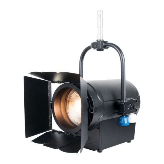
Page 9: Overview
OVERVIEW 1. Junior Pin 11. Enter Button 2. Mounting Bracket 12. Down Button 3. Power Out 13. Up Button 4. Power In 14. Mode Button 5. DMX Out (3-pin) 15. Zoom Adjustment Knob 6. DMX Out (5-pin) 16. USB Port 7. -
Page 10: Fixture Installation
FIXTURE INSTALLATION FLAMMABLE MATERIAL WARNING Keep fixture minimum 5.0 feet (1.5m) away from flammable materials and/or pyrotech- nics. ELECTRICAL CONNECTIONS A qualified electrician should be used for all electrical connections and/or installations. MINIMUM DISTANCE TO OBJECTS/SURFACES IS 1 FOOT (0.3 METERS) MINIMUM DISTANCE OF FLAMMABLE MATERIALS FROM THE SURFACE IS 1.6 FEET (0.5 METER) MAXIMUM AMBIENT TEMPERATURE 113°... - Page 11 FIXTURE INSTALLATION CLAMP INSTALLATION A mounting clamp can be attached to the top of the junior pin for mounting purposes. The device also features an attachment point for a safety cable on the rear of the housing (see the illustration below for reference).
-
Page 12: Accessory Installation
ACCESSORY INSTALLATION GEL FRAME / BARNDOOR INSTALLATION 1. Press the frame latch release and lift the latch 2. Slide the barndoor assembly into place in release, as indicated by the two red arrows. front of the gel frame. Slide the gel frame into place in front of the lens. 3. -
Page 13: Control Panel
CONTROL PANEL The fixture includes an easy to navigate system menu. The control panel display is located on the rear panel of the fixture (see image below) and provides access to the main system menu, where all necessary system adjustments are made to the fixture. During normal operation, pressing the MODE button once will access the fixture’s main menu. -
Page 14: System Menu
SYSTEM MENU ELATION KL FRESNEL 8 PO Supports Software Versions: 1.08 ADDRESS 001 - 511 Address “XXX” Dimmer Dimmer 16bit USERMODE Standard Extended Black / Hold Status Lost DMX On / Off Display 30 S lock display On / Off... - Page 15 SYSTEM MENU ELATION KL FRESNEL 8 PO Supports Software Versions: 1.08 900, 1000, 1100, 1200, 1300, 1400, Frequen 1500, 2500, 4000, 5000, 10k, 15k, 25k, 25k (Hz) FUNCTION (CONTIN- On / Off USB Data UED) On / Off Primary On / Off...
-
Page 16: Dmx Channel Functions
DMX CHANNEL FUNCTIONS ELATION KL FRESNEL 8 PO Supports Software Versions: 1.08 Dimmer Dimmer Standard Extended Function 16bit Values 000 - 255 Intensity, close to open 000 - 255 Intensity Fine, close to open Strobe 000 - 031 Closed 032 - 063 Open... - Page 17 DMX CHANNEL FUNCTIONS ELATION KL FRESNEL 8 PO Supports Software Versions: 1.08 Dimmer Dimmer Standard Extended Function 16bit Values Dimmer Delay Time (continued) 4.0s 5.0s 6.0s 7.0s 8.0s 9.0s 142 - 255 Default Control (hold for 3s) 000 - 100 Idle...
-
Page 18: Dimmer Modes And Curves
DIMMER MODES & CURVES... -
Page 19: Manual Dimming And Zoom Control
MANUAL DIMMING AND ZOOM CONTROL Follow steps below to enable manual DIMMING and ZOOM control knobs. 1. Disconnect any DMX cables from the device. 2. From the main system menu, select the “Test” option, then select the “Man Ctrl” sub-menu. See the System Menu section of this manual for details. -
Page 20: Specifications
SPECIFICATIONS SOURCE 350W Warm or Cool White LED Engine 14,000 Total Output Lumens, 3,000K, 96CRI 50,000 Hour Average LED Life* *May vary depending on several factor, including but not limited to: environmental conditions, power and voltage, usage patterns (on- off cycling), control, and dimming. PHOTOMETRIC DATA 19,410 LUX 1,803 FC @ 9.8’... -
Page 21: Dimensional Drawings
DIMENSIONAL DRAWINGS Dimensions may not be drawn to scale.
Need help?
Do you have a question about the KL FRESNEL 8 PO and is the answer not in the manual?
Questions and answers