Advertisement
Advertisement
Table of Contents

Subscribe to Our Youtube Channel
Related Manuals for Elation PULSE BAR S


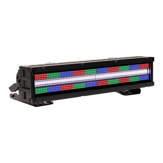
Summary of Contents for Elation PULSE BAR S
- Page 1 User Manual...
- Page 2 Elation Professional B.V. | Junostraat 2 | 6468 EW Kerkrade, The Netherlands +31 45 546 85 66 | +31 45 546 85 96 fax | www.elationlighting.eu | info@elationlighting.eu Elation Professional Mexico | AV Santa Ana 30 | Parque Industrial Lerma, Lerma, Mexico 52000...
-
Page 3: Table Of Contents
Warranty Returns (USA Only) Safety Guidelines Overview Torque Settings for Screws IP Test Parameters Installation Guidelines Accessory Installation Remote Device Management (RDM) Pulse Bar S Feature Guide System Menu/Software Updates Dimmer Modes & Curves DMX Traits Zone Layouts Error Codes Maintenance Guidelines Specifications... - Page 4 - Safety Cable - IP65 Locking Power Cable - Fixture Interconnect Splice CUSTOMER SUPPORT Contact ELATION Service for any product related service and support needs. Also visit forums.elationlighting.com with questions, comments, or suggestions. ELATION SERVICE USA - Monday - Friday 8:00am to 4:30pm PST 323-582-3322 | support@elationlighting.com...
-
Page 5: Ip65 Rated
I P 6 5 R AT E D The International Protection (IP) rating system is commonly expressed as “IP” (Ingress Protection) followed by two numbers (i.e. IP65), where the numbers define the degree of protection. The first digit (Foreign Bodies Protection) indicates the extent of protection against particles entering the fixture, and the second digit (Water Protection) indicates the extent of protection against water entering the fixture. -
Page 6: Warranty Returns (Usa Only)
It is the owner’s responsibility to establish the date and place of purchase by acceptable evidence, at the time service is sought. B. For warranty service, send the product only to the Elation Professional factory. All shipping charges must be pre-paid. If the requested repairs or service (including parts replacement) are within the terms of this warranty, Elation Professional will pay return shipping charges only to a designated point within the United States. -
Page 7: Safety Guidelines
S A F E T Y G U I D E L I N E S This fixture is a sophisticated piece of electronic equipment. To guarantee smooth operation, it is important to follow all instructions and guidelines in this manual. Elation Professional is not responsible for injury and/or damages resulting from the misuse of this fixture due to the disregard of the information printed in this manual. - Page 8 S A F E T Y G U I D E L I N E S RISK GROUP 3 - RISK OF EXPOSURE TO ULTRAVIOLET UV RADIATION! FIXTURE EMITS HIGH INTENSITY WAVELENGTH OF ULTRAVIOLET UV LIGHT FROM THE UV COLOR FILTER. WEAR PROPER SKIN...
-
Page 9: Overview
O V E R V I E W Fixture Interconnect Slot S S a a f f e e t t y y C C a a b b l l e e M M u u l l t t i i - - p p o o s s i i t t i i o o n n L L - - T T r r a a c c k k A A t t t t a a c c h h m m e e n n t t P P o o i i n n t t A A i i r r V V a a l l v v e e... -
Page 10: Torque Settings For Screws
Rear Cover (10±0.5/Kgf.cm) (13±0.5/Kgf.cm) End Cover (13±0.5/Kgf.cm) Adjustable Trunnion (10±0.5/Kgf.cm) CAUTION! DO NOT OVER TORQUE SCREWS AS THIS CAN CAUSE LEAKAGE ISSUES! TO CONFIRM THE IP65 INTEGRITY, TEST FIXTURE USING THE ELATION IP TESTER. CONTACT ELATION SERVICE FOR MORE DETAILS. -
Page 11: Ip Test Parameters
Following any repair or maintenance procedure that requires disassembly of the fixture, use Elation’s IP Tester to confirm the IP integrity of the fixture. The air valve is located on the back panel next to the display screen, as shown in the diagram below. Please contact Elation... -
Page 12: Installation Guidelines
I N S TA L L AT I O N G U I D E L I N E S FLAMMABLE MATERIAL WARNING Keep fixture minimum 5.0 feet (1.5m) away from flammable materials and/or pyrotechnics. ELECTRICAL CONNECTIONS A qualified electrician should be used for all electrical connections and/or installations. - Page 13 I N S TA L L AT I O N G U I D E L I N E S CLAMP INSTALLATION This device features a mounting clamp attachment point built into the Adjustable Trunnions, as well as a safety cable attachment point located on the bottom of the fixture. OMEGA BRACKETS WITH CLAMP INSTALLATION Insert the Omega Brackets into the matching holes on the Adjustable Trunnion.
- Page 14 I N S TA L L AT I O N G U I D E L I N E S L-TRACK MOUNTING The L-track mounting system enables the user to slide the mounting clamps along the tracks and secure them in the desired position. The L-tracks are situated on the Rear, and along the sides of the fixture.
- Page 15 I N S TA L L AT I O N G U I D E L I N E S FIXTURE INSTALLATION The Elation PULSE BAR S is fully operational in three different mounting positions, hanging upside-down, mounted sideways on trussing, or set on a flat level surface. Always use and install the supplied safety cable as a safety measure to prevent accidental damage and/or injury in the event the clamp fails.
- Page 16 I N S TA L L AT I O N G U I D E L I N E S FIXTURE INTERCONNECTORS To connect the fixtures end-to-end, ensure that the interconnect slots are flush. Fully insert the splice lock. Once the splice lock is fully seated, turn the lock tab to engage it, rotating the lock tab into the interconnect lock slot.
- Page 17 I N S TA L L AT I O N G U I D E L I N E S RIGGING LIMIT HORIZONTAL SUSPENSION When utilizing the provided Trunnions for rigging in a horizontal array orientation, the maximum capacity is 4 fixtures, or 96 lbs (43.54 kg).
- Page 18 I N S TA L L AT I O N G U I D E L I N E S ART-NET | sACN CONNECTION When connecting fixture to a network switch to control multiple devices, a Gigabit Ethernet Switch that supports IGMP (Internet Group Management Protocol) is required. Using a Gigabit Ethernet Switch that does not support IGMP can cause erratic behavior of all connected devices to the switch.
- Page 19 LEDs. This issue is not specific only to ELATION lighting fixtures, it is a common issue with lighting fixtures from all manufacturers. Although there is no true way to fully prevent this issue from happening, the guidelines below can prevent any potential damage from occurring if followed.
- Page 20 A C C E S S O RY I N S TA L L AT I O N - F R O S T L E N S 1. Slide lock levers downward to retract the locking tabs. 2. Install the Frost Lens by sliding it into the lens groove. 3.
- Page 21 ACCESSORY INSTALLATION - GLARE SHIELD (OPTIONAL) 1. Locate two Glare Shield mounting screw holes on side of fixture. 2. Align the thumbscrews of the Glare Shield with the mounting screw holes and insert them. 3. Tighten the two thumbscrews to secure Glare Shield. Thumbscrews can also be tightened with a Phillips screw driver.
- Page 22 R E M O T E D E V I C E M A N A G E M E N T ( R D M ) NOTE: In order for RDM to work properly, RDM enabled equipment must be used throughout the entire system, including DMX data splitters and wireless systems.
- Page 23 P U L S E B A R L F E AT U R E G U I D E The Pulse Bar S is distinguished from other fixtures by offering more individually controllable zones and LED types. While this feature is distinctive, there may be instances where users desire less control.
- Page 24 AC100-240V 50/60Hz MAX:100-240V 9A FUSE:T8A / 250V AN ELATION C-LOADER II CAN ALSO BE USED TO UPDATE THE FIXTURE TO THE LATEST SOFTWARE. To order this device, please contact Elation Support for further details. Detailed instructions can be found online at www.elationlighting.com.
- Page 25 S YS T E M M E N U MAIN MENU OPTIONS / VALUES (Default Settings in BOLD) DMX Address 001 - 512 3CH Xenon Strb 11CH Simple Strb 22CH Strobe FX 34CH Large Pixel DMX Mode 52CH Simple Pxl 124CH Pxl Focus 77CH Basic Full 132CH Full Mode...
- Page 26 SYSTEM MENU MAIN MENU OPTIONS / VALUES (Default Settings in BOLD) Current Run Time Time Total Run Time Last Run Time Current Temperature Max Resettable Information DMX Values Green Product IDs RDM UID Error Logs Fixture Errors Software Version Vx.x Update Firmware On / Off All Red 000-255 All Green 000-255...
- Page 27 D I M M E R M O D E S & C U R V E S DIMMER 100% Time (ms) 0 Sec Rise Time Down Time 0 sec Fade Time 1 sec Fade Time Dimming Curve Ramp Effect Rise Time (ms) Down Time (ms) Rise Time (ms) Down Time (ms) Standard (default) Stage...
- Page 28 D M X T R A I T S Basic Fixture Xenon Simple Strobe Large Simple Pixel Full Full Snap Default Part Strobe Strobe Pixels Pixel Focus Control Mode Function Control Values Value Name 11CH 22CH 34CH 52CH 124CH 132CH 110CH 77CH Master Dimmer...
- Page 29 D M X T R A I T S Basic Fixture Xenon Simple Strobe Large Simple Pixel Full Full Snap Default Part Strobe Strobe Pixels Pixel Focus Control Mode Function Control Values Value Name 11CH 22CH 34CH 52CH 124CH 132CH 110CH 77CH CW Strobe Effect Selelection...
- Page 30 D M X T R A I T S Basic Fixture Xenon Simple Strobe Large Simple Pixel Full Full Default Part Strobe Strobe Pixels Pixel Focus Control Mode Function Snap Control Values Value Name 11CH 22CH 34CH 52CH 124CH 132CH 110CH 77CH RGB Effect Offset...
- Page 31 D M X T R A I T S Basic Fixture Xenon Simple Strobe Large Simple Pixel Full Full Default Part Strobe Strobe Pixels Pixel Focus Control Mode Function Snap Control Values Value Name 11CH 22CH 34CH 52CH 124CH 132CH 110CH 77CH Control...
- Page 32 D M X T R A I T S Basic Fixture Xenon Simple Strobe Large Simple Pixel Full Full Default Part Strobe Strobe Pixels Pixel Focus Control Mode Function Snap Control Values Value Name 11CH 22CH 34CH 52CH 124CH 132CH 110CH 77CH 1340...
- Page 33 D M X T R A I T S Basic Fixture Xenon Simple Strobe Large Simple Pixel Full Full Snap Default Part Strobe Strobe Pixels Pixel Focus Control Mode Function Control Values Value Name 11CH 22CH 34CH 52CH 124CH 132CH 110CH 77CH Red 1...
- Page 34 D M X T R A I T S Basic Fixture Xenon Simple Strobe Large Simple Pixel Full Full Snap Default Part Strobe Strobe Pixels Pixel Focus Control Mode Function Control Values Value Name 11CH 22CH 34CH 52CH 124CH 132CH 110CH 77CH Red 11...
- Page 35 D M X T R A I T S Basic Fixture Xenon Simple Strobe Large Simple Pixel Full Full Snap Default Part Strobe Strobe Pixels Pixel Focus Control Mode Function Control Values Value Name 11CH 22CH 34CH 52CH 124CH 132CH 110CH 77CH CW Strobe 1...
- Page 36 D M X T R A I T S Basic Fixture Xenon Simple Strobe Large Simple Pixel Full Full Snap Default Part Strobe Strobe Pixels Pixel Focus Control Mode Function Control Values Value Name 11CH 22CH 34CH 52CH 124CH 132CH 110CH 77CH StrobeLine Red 1...
- Page 37 Z O N E L AY O U T S FULL CONTROL, FULL RAW, AND PIXEL FOCUS ZONING RGB Zone CW Strobe RGB StrobeLine CW Strobe RGB Zone SIMPLE PIXEL ZONING RGB Zone CW Strobe RGB StrobeLine (CW Only) CW Strobe RGB Zone BASIC FULL CONTROL ZONING RGB Zone...
- Page 38 E R R O R C O D E S Error Codes subject to change without notice ERROR CODES DESCRIPTION Temp Error This message appears when there is a heating error.
- Page 39 Regular inspections are recommended to insure proper function and extended life. There are no user serviceable parts inside this fixture. Please refer all other service issues to an authorized Elation service technician. Should you need any spare parts, please order genuine parts from an authorized Elation dealer.
- Page 40 S P E C I F I C AT I O N S SOURCE (560) 1.5W RGB LEDs (200) 5W CW Strobe LEDs 50,000 Hour Average LED Life* *May vary depending on several factors including but not limited to: Environmental Conditions, Power/Voltage, Usage Patterns (On-Off Cycling), Control and Dimming.
- Page 41 D I M E N S I O N D R AW I N G S Drawings not to scale 19.7in. [501.2mm] 16.3in. [415.0mm] 18.9in. [480.0mm] 13.8in. [350.0mm] 5.1in. [129.1mm] 6.9in. [175.5mm] 6.9in. [175.5mm] 8.1in. [204.6mm]...
- Page 42 O R D E R I N G I N F O R M AT I O N SKU US/EU ITEM DESCRIPTION SIX226 1237000341 PULSE BAR S BLS061 1223200108 BAR S WFL BLS021 1223200117 BAR S NSP BLS101 1223200116 BAR S XFL...
Need help?
Do you have a question about the PULSE BAR S and is the answer not in the manual?
Questions and answers