Table of Contents
Advertisement
Advertisement
Table of Contents

Related Manuals for Mitsubishi Electric Climaveneta i-BX-004-013M


Summary of Contents for Mitsubishi Electric Climaveneta i-BX-004-013M
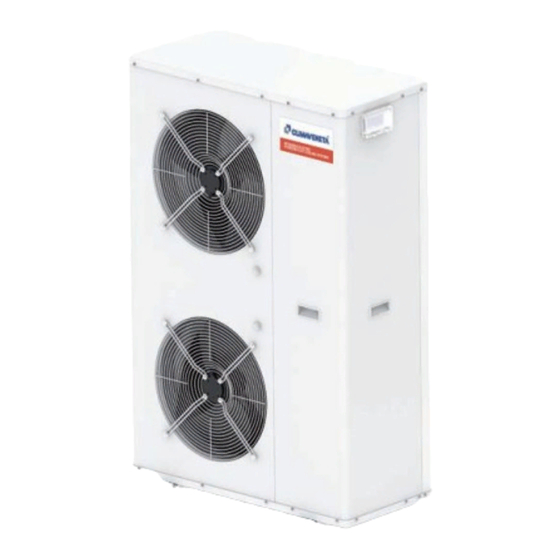
- Page 1 INSTALLATION - OPERATING - SERVICE MANUAL i-BX-(Y) Air-source liquid chiller for outdoor installation 4,3-35,1 kW i-BX-N-(Y) Air-source reverse-cycle heat pump for outdoor installation 4,2-35,1 kW i-BX-(Y) 004-013M i-BX-(Y) 010-035T i-BX-N-(Y) 004-013M i-BX-N-(Y) 010-035T...
- Page 2 U I A U I A U I A INDEX U I A General warnings Checking and starting up the unit Safety rules Menu structure and access modes U I A Waiver of liability Setting the time and date Fundamental safety rules Setting the DHW set point Receiving and handling the product Control and operating characteristics...
-
Page 3: General Warnings
U I A GENERAL WARNINGS These appliances have been designed to chill and/or without the presence of personnel authorised by the heat water and must be used in applications compatible Company (where specified in the supply contract) who with their performance characteristics; these appliances should draw up a “start-up”... - Page 4 U I A SAFETY RULES performed; do not wear clothes or accessories that may or damaging objects; if necessary, suitably connect the get caught on objects or be sucked in by air flows; restrain discharges as specified by EN 378-3 and local laws in and tie back long or loose hair before accessing the inside force, making sure to carry fluids in any safety group other of the unit...
-
Page 5: General Precautions
U I A SAFETY RULES GENERAL PRECAUTIONS evaporative towers, zone valves, …), adequate sizing of • during storage and the transport, depending on the refrig- the mass of fluid circulating in the system (especially when erant charged in the unit, keep the unit within the following certain zones of the system are bypassed) and installation temperature limits (wider limits are possible and must be of systems for recirculating the flow-rate of fluid needed to... -
Page 6: Receiving And Handling The Product
RECEIVING AND HANDLING THE PRODUCT VISUAL INSPECTION STORING THE UNITS When the items are consigned by the carrier: The units must be stored sheltered from direct sunlight, rain, - make sure that the goods delivered correspond to the wind or sand. description on the delivery note, comparing this against Avoid exposing the units to direct sunlight, as the pressure the data on the packaging label. -
Page 7: Removing The Packaging
RECEIVING AND HANDLING THE PRODUCT REMOVING THE PACKAGING The packaging must be removed by the operator using suit- able protective equipment (gloves, glasses, etc.). Take special care not to damage the unit. Observe the local standards in force as regards disposal of the packaging, using specialist collection or recycling centres. -
Page 8: Unit Identification
U I A UNIT IDENTIFICATION The heat pump can be identified from: PACKAGING LABEL Packaging label Describes the product identification data RATING PLATE Describes the unit technical and performance specifications. Shows the serial number used to uniquely identify the unit. The serial number is also used to identify the unit’s spare parts. - Page 9 DESCRIPTION OF STANDARD UNIT Electrical panel System plate heat exchanger DC inverter compressor Inverter driver Water flow switch Electronic Expansion valve Axial-flow fan Finned heat exchanger, air side System pump 10 4-way reversing valve (i-BX-N only) 11 Anti-acid filter-drier 12 Liquid receiver (i-BX-N only) 13 Expansion vessel 14 Liquid separator (i-BX-N only) EN i-BX-(Y)_i-BX-N-(Y)
-
Page 10: Dimensional Drawings
U I A DIMENSIONAL DRAWINGS Weight Size [mm] [mm] [mm] [mm] [mm] [mm] [kg] [kg] [kg] [kg] [kg] i-BX-(Y) 004 i-BX-(Y) 006 i-BX-(Y) 008 1240 i-BX-(Y) 010 1240 i-BX-(Y) 013 1240 i-BX-(Y) 015 1240 i-BX-N-(Y) 004 i-BX-N-(Y) 006 i-BX-N-(Y) 008 1240 i-BX-N-(Y) 010 1240 i-BX-N-(Y) 013... -
Page 11: Choice Of Installation Site
INSTALLATION CHOICE OF INSTALLATION SITE Before installing the unit, agree with the customer the site where it will be installed, taking the following points into con- sideration: • check that the support surface is adequate to support the weight of the unit; •... - Page 12 INSTALLATION POSITIONING • Install the vibration damping feet (accessories). • Check the unit supports and weights before positioning • Make sure that the unit is level, adjust the height of the support feet if necessary • Use the flexible joints supplied for the water connections •...
-
Page 13: Water Connections
WATER CONNECTIONS Warnings - The choice and installation of components is the responsi- Before connecting the pipes make sure that these: bility of the installer who should follow good working prac- - do not contain stones, sand, rust, scale or any foreign tice and current legislation. -
Page 14: Risk Of Freezing
WATER CONNECTIONS Components and the expected operating temperature, otherwise The following components should be installed for correct install an additional expansion vessel. installation of the unit: 10. The connection piping should be supported in such a 1. Two pressure gauges with a suitable scale (inlet and out- way as to avoid it weighing on the unit. - Page 15 WATER CONNECTIONS Fouling factors Evaporator Fouling factors °C/W) The performance data given refer to conditions with clean evaporator plates (fouling factor = 1). 4,4 x 10 For different fouling factors, multiply the figures in the perfor- 0,86 x 10 0,96 0,99 0,99 mance tables by the coefficient given in the following table.
- Page 16 U I A WATER CONNECTIONS System water circuit connection diagram, i-BX version without pump FACTORY INSTALLER CONNECTIONS CONNECTIONS UTILITY RETURN UTILITY OUTLET Pressure gauge Flow switch Expansion vessel 13 System vent Vibration damper joint Thermometer 10 Wire mesh filter 14 Drain / chemical washing valve Shut-off valve Circulating pump 11 Fill –...
- Page 17 U I A WATER CONNECTIONS System water circuit connection diagram, i-BX with pump Pressure gauge Flow switch Expansion vessel 13 System vent Vibration damper joint Thermometer 10 Wire mesh filter 14 Drain / chemical washing valve Shut-off valve Circulating pump 11 Fill –...
-
Page 18: Filling The System
U I A WATER CONNECTIONS Condensate drain (for i-BX-N units only) • Condensate drainage must not cause problems to objects In heating mode the units produce a significant quantity of or people. condensate. In cold areas, do not use a drain pipe with the •... - Page 19 ELECTRICAL CONNECTIONS In the case of three phase units, ensure the phases are connected correctly. Do not use water pipes to earth the unit. Electrical data at maximum conditions allowed (full load) Unit without hydronic unit Power supply Total power consumption Fuses (5x20T 250V) Model Size...
- Page 20 MAINS POWER SUPPLY CONNECTIONS • Before connecting the unit to the power supply, makes sure that switch QF1 is open, suitably padlocked and marked. • Remove the panel by removing the screws. The panel must first be pulled out and then removed. Only for Extrao tion...
-
Page 21: Installer Connections
INSTALLER CONNECTIONS YV5 3-way valve for domestic hot water production Heat pump 3-way valve (i-BX-N only) Installer terminal block The 3-way valve installed outside of the unit deviates the flow of hot water produced by the unit to the DHW storage tank. - Page 22 INSTALLER CONNECTIONS Solution 2 System with heat pump and outlet electric heater WITHOUT storage tank. 12 22 25 34 Position probe BT9 on the system outlet pipe. 230V / 400V Outlet electric heater control Outlet electric heater operating parameters in REPLACE- (i-BR-N only) (only if boiler is not enabled) MENT mode Description...
- Page 23 COLLEGAMENTO ELETTRICO DI POTENZA ALLA RETE DI ALIMENTAZIONE INSTALLER CONNECTIONS Supplementary heating always enabled Outlet electric heater operating parameters in SUPPLE- Supplementary heating with the electric heater is enabled MENTARY mode when always ENABLED for all outside air temperatures. Description Menu Parameter Value to be...
-
Page 24: Boiler Control
COLLEGAMENTO ELETTRICO DI POTENZA ALLA RETE DI ALIMENTAZIONE INSTALLER CONNECTIONS S8 Boiler (i-BX-N only) A boiler can be used as a supplementary or replacement heat source for the system. 18 19 25 34 Solution 1 System with heat pump and boiler with storage tank. Boiler Solution 2 System with heat pump and boiler without storage tank. - Page 25 INSTALLER CONNECTIONS Supplementary heating always enabled Boiler operating parameters in SUPPLEMENTARY mode Supplementary heating by boiler is enabled for all outside when always ENABLED air temperatures. Description Menu Parameter Value to be To enable heating at all times set parameter 0306 = 0 and 010H = 0 Activation Boiler Mn03...
- Page 26 INSTALLER CONNECTIONS KM4 DHW storage electric heater An electric heater can be managed for heating the DHW storage. 13 22 DHW storage electric heater control The electric heater is activated to reach a temperature value that the heat pump on its own is not able to reach. Example: Domestic hot water temperature produced with heat pump 0023 = 55°C...
- Page 27 U I A INSTALLER CONNECTIONS Radiant panel zone management a circulating pump and a manifold temperature probe. The NADI controller can manage a low temperature zone for The operating modes are described in the chapter on “Con- radiant panel systems. trol and operating characteristics”...
-
Page 28: Alarm Signal
INSTALLER CONNECTIONS HL1 Configurable contact This contact can be configured for the following functions: • Alarm signal • Secondary circuit pump • Dehumidifier Alarm signal A visual or audible signal device can be activated if the unit shuts down due to a malfunction. Configure the contact, selecting the desired function by set- ting parameter 015A: 16 17... - Page 29 INSTALLER CONNECTIONS Contact SA8 configured as “cooling/heating signal”: Contact SA9 configured as “cooling/heating signal”: Description Menu Parameter Value to be Description Menu Parameter Value to be Enable contact as: Mn01 015C SUMMER Enable contact as: Mn01 011B SUMMER/ - BOILER SYSTEM WINTER - DHW RECIRCULATION WINTER...
- Page 30 INSTALLER CONNECTIONS SA3 Remote system/domestic water priority The priority of heat pump operation can be selected using a remote contact. Use a three-position selector to set the following functions: 28 25 29 1 = System only 0 = Domestic hot water + System 1 0 2 2 = Domestic hot water only Set the following parameters:...
- Page 31 INSTALLER CONNECTIONS SA6 Reduced electricity rate contact Forced refilling of the reserve storage tanks can be activat- ed based on different electricity rates during the day. During reduced rate periods, the heat pump can be forced 31 25 on so as to heat the domestic hot water, where fitted. Contact closed: forced operation during the reduced rate period.
- Page 32 INSTALLER CONNECTIONS Contact SA7 configured as “boiler backup” Description Menu Parameter Value to be 32 25 Enable contact as: Mn01 011C BOILER - DHW FLOW-SWITCH BACkUP - BOILER BACkUP - DEHUMIDIFIER The boiler backup function must be configured for only one of the configurable contacts listed.
-
Page 33: General Technical Data
GENERAL TECHNICAL DATA i-BX Power supply V/ph/Hz 230/1/50 400/3+N/50 COOLING ONLY (GROSS VALUE) Cooling capacity 4,30 6,11 8,10 10,60 12,90 10,70 13,30 15,50 20,60 25,00 29,80 35,10 Total power input 1,55 2,12 2,82 3,64 4,74 3,64 4,74 5,44 7,20 8,69 10,00 11,80 kW/kW 2,77 2,88... - Page 34 GENERAL TECHNICAL DATA i-BX-N Power supply V/ph/Hz 230/1/50 400/3+N/50 COOLING ONLY (GROSS VALUE) Cooling capacity 4,20 5,90 7,50 9,90 12,40 10,50 12,80 14,70 18,70 24,70 29,40 35,10 Total power input 1,55 2,08 2,72 3,64 4,54 3,64 4,54 5,24 7,00 8,99 10,50 12,70 kW/kW 2,71 2,84...
-
Page 35: Operating Limits
OPERATING LIMITS i-BX-N operation in HEATING mode and for DOMESTIC HOT WATER PRODUCTION Air intake temperature [°C] Operation in heating mode: System circuit temperature difference, minimum 4°k, maximum 10°k Maximum glycol content 40% Maximum water inlet temperature at plate heat exchanger +50°C with temperature difference of 10°k Minimum water inlet temperature at plate heat exchanger +20°C i-BX-N operation in COOLING mode OPERATING RANGE WITH WATER-GLYCOL MIXES... - Page 36 OPERATING LIMITS i-BX operation in COOLING mode OPERATING RANGE WITH WATER-GLYCOL MIXES Air intake temperature [°C] Operation in cooling mode: System circuit temperature difference, minimum 3°k, maximum 8°k Maximum glycol content 40% i-BX-(Y)_i-BX-N-(Y) EN...
-
Page 37: Pump Curve
PUMP CURVE i-BX-(Y) / i-BX-N-(Y) 004M i-BX-(Y) / i-BX-N-(Y) 006M Flow Q [m Flow Q [m i-BX-(Y) / i-BX-N-(Y) 010M i-BX-(Y) / i-BX-N-(Y) 008M Flow Q [m Flow Q [m i-BX-(Y) / i-BX-N-(Y) 013M Flow Q [m The pressure head values refer to the pressure available at the connections to the unit. EN i-BX-(Y)_i-BX-N-(Y) - Page 38 PUMP CURVE i-BX-(Y) / i-BX-N-(Y) 013T i-BX-(Y) / i-BX-N-(Y) 010T Flow Q [m Flow Q [m i-BX-(Y) / i-BX-N-(Y) 020T i-BX-(Y) / i-BX-N-(Y) 015T Flow Q [m Flow Q [m i-BX-(Y) / i-BX-N-(Y) 030T i-BX-(Y) / i-BX-N-(Y) 025T 10,0 Flow Q [m Flow Q [m i-BX-(Y) / i-BX-N-(Y) 035T 10,0...
- Page 39 PUMP CURVE PRESSURE DROP, VERSION WITHOUT PUMP Flow rate [m 10,0 11,0 Flow rate [m EN i-BX-(Y)_i-BX-N-(Y)
-
Page 40: Checking And Starting Up The Unit
CHECKING AND STARTING UP THE UNIT CHECKS BEFORE STARTING THE UNIT • the vibration damping feet are fitted • make sure the position of the outside air probe corre- • inlet filters are fitted on the system and domestic hot water sponds to the instructions shown in the manual circuits •... - Page 41 CHECKING AND STARTING UP THE UNIT DESCRIPTION CONTROLLER BUTTONS AND DISPLAY User keypad on the unit General functions of the buttons Button Description [PRG button]: access the main menu [UP button]: navigate the screens and set the values of the control parameters [DOWN button]: navigate the screens and set the values of the control parameters [ENTER button]: confirm the set data [ESC button]: go back one level in the screen tree, when in the screen header, or to go back to the main...
-
Page 42: Symbols On Screen
CHECKING AND STARTING UP THE UNIT Once having powered up the heat pump, the display on the control unit shows “Loading...” Wait a few minutes, the unit is ready to operate when the display shows the first summary screen, screen 1. Symbols on screen 1 1 Time (__:__) 6 Unit water outlet temperature... - Page 43 CHECKING AND STARTING UP THE UNIT The UP and DOWN buttons can be used to scroll all of the screens that show the instant data corresponding to unit status, screens 2 to 11: Screen 2a SCREEN 2a High temperature system information The number of screens corresponds to the number of high temperature system configurations 1 Zone no.
- Page 44 CHECKING AND STARTING UP THE UNIT SCREEN 3 Screen 3 Thermostatic valve Visible only with password 1 Thermostatic valve opening 4 Evaporation pressure [bar] [step] (max 480 steps) 5 Evaporation temperature con- 2 Thermostatic valve opening verted from pressure [%] (max 100 %) 6 Suction temperature measured 3 Valve status (Std-by - Pos - On by probe...
- Page 45 CHECKING AND STARTING UP THE UNIT Screen 7 SCREEN 7 System pump 1 Water temperature set point 3 Temperature difference DT [°C] 4 Water inlet temperature [°C] 2 System pump status (On - Off 5 Water outlet temperature [°C] - Sniffing) SCREEN 8 Screen 8 DHW side...
- Page 46 CHECKING AND STARTING UP THE UNIT Warning: before starting, leave power connected to the unit with the compressor off for at least two hours, so as to preheat the oil in the compressor sump. The following operating modes can be selected, according to the model: Heating only* Heating system and domestic hot water* Cooling only...
- Page 47 CHECKING AND STARTING UP THE UNIT Use thei buttons to set the desired operating status (“ON” or “OFF”) Press the button to confirm and return to the main screen (in the example on the side, the unit is enabled for heating operation and domestic hot water production).
- Page 48 MENU STRUCTURE AND ACCESS MODES Menu structure Level Password Menus enabled Menu code User 0012 Room unit Mnu00 System config. Mnu01 Mnu02 Supplementary sources Mnu03 Installer 0034 Cascade / AHU Mnu04 DHW heat exchanger Mnu06 Mnu09 Source heat exchanger Mnu07 Compressor Mnu05 Defrost...
-
Page 49: Setting The Time And Date
MENU STRUCTURE AND ACCESS MODES Press the button to display the parameters in the select- ed menu. Use the buttons to scroll to and select the desired parameter. Press , the cursor moves to the value being set. To change the value press Confirm the changes with the button (press repeatedly until the cursor returns to the top left). -
Page 50: Temperature Control
CONTROL AND OPERATING CHARACTERISTICS Temperature control The heating or cooling circuit water temperature is calculat- ed by the controller and depends on the following factors: A) system water set point compensation in heating or cool- ing (see paragraph) B) room temperature influence (see paragraph) C) minimum and maximum heating water temperature limit (see paragraph) D) room temperature set point... - Page 51 CONTROL AND OPERATING CHARACTERISTICS B) Room temperature influence in HEATING* Example referred to compensation curve 1.0 Function only active if the N-THC room control units (acces- sory) are installed. The compensation curve determines the heating water tem- perature; this may then be corrected based on the difference 10 % between the desired room set point and the actual room tem- 25 %...
- Page 52 CONTROL AND OPERATING CHARACTERISTIC Description Menu arameter Default Water set point compensation diagram in COOLING The compensation curve in cooling mode can be modified to Enable SYSTEM compensation curve Mn01 0154 allow correct heat pump operation depending on the cooling system used (radiant panels, fan coils).
- Page 53 CONTROL AND OPERATING CHARACTERISTICS Automatic mode changeover based on outside Heating Cooling temperature In AUTOMATIC mode, the operating mode (heating / cool- ing) changes automatically, avoiding the need for the user to change the mode manually. Mode changeover is based on the diagram shown in the fig- Outside temp.
-
Page 54: Frost Protection
U I A CONTROL AND OPERATING CHARACTERISTICS Description Menu Parameter Default Heat pump operation with fixed set point Enable set point in HEATING, SYSTEM Mn01 0152 System water set point compen- sation using the compensation Fixed water temperature set point in HEATING, SYSTEM Mn01 0153 °C... - Page 55 U I A SYSTEM CONFIGURATION The heat pump controller can select configurations for different types of system by setting parameter 0101. The following table describes the system configurations available. High temperature Parameter Menu Mixed zone 1 zone 1 0101 recirculation (fan coils / radiators) ZONA "1"...
-
Page 56: Installation Procedure
U I A INSTALLATION AND CONNECTION OF N-THC ROOM CONTROL UNITS The N-THC room control units can manage up to two zones, controlling temperature and humidity according to the selected configuration; see the diagrams below. Installation instructions The room controller must be installed in the best reference position for temperature control. - Page 57 U I A INSTALLATION AND CONNECTION OF N-THC ROOM CONTROL UNITS • Close the cover A1 and secure it with the screw A2 inside to ensure correct fastening (click on). • Plug in the 4-pin connector, figure (7) • Dimensions of A5 room controller figure (8). •...
-
Page 58: System Configuration
U I A SYSTEM CONFIGURATION Heat pump connection to the system without low-loss header. Make sure the useful pressure head of the circulating pump on the unit is sufficient for the pressure drop in the sys- tem. If the minimum system content does not reach values shown in this manual, install an additional storage tank on the heat pump return pipe. -
Page 59: Parameter Configuration
U I A SYSTEM CONFIGURATION Parameter configuration Description Menu Parameter no. Default Write set value SYSTEM compensation curves in HEATING mode Enable SYSTEM compensation curve Mn01 0152 SYSTEM compensation curve number Mn01 0159 SYSTEM compensation curves in cooling mode Enable SYSTEM compensation curve Mn01 0154 Maximum temperature set point limit in cooling mode (Tm1) -
Page 60: System Number
U I A SYSTEM CONFIGURATION System number 0 Water circuit diagram Water circuit diagram (not a working drawing) i-BX-(Y)_i-BX-N-(Y) EN... - Page 61 U I A SYSTEM CONFIGURATION System number 0 Wiring diagram EN i-BX-(Y)_i-BX-N-(Y)
- Page 62 U I A SYSTEM CONFIGURATION System number 0 Parameter configuration Description Menu Parameter no. Default Write set value Enable zone management Mn01 016A System type (table 1) Mn01 0101 SYSTEM compensation curves in heating mode Enable SYSTEM compensation curve Mn01 0152 SYSTEM compensation curve number Mn01...
- Page 63 U I A SYSTEM CONFIGURATION System number 1 Water circuit diagram Water circuit diagram (not a working drawing) EN i-BX-(Y)_i-BX-N-(Y)
- Page 64 U I A SYSTEM CONFIGURATION System number 1 Wiring diagram i-BX-(Y)_i-BX-N-(Y) EN...
- Page 65 U I A SYSTEM CONFIGURATION System number 1 Parameter configuration Description Menu Parameter no. Default Write set value Enable zone management Mn01 016A System type (table 1) Mn01 0101 SYSTEM compensation curves in heating mode Enable SYSTEM compensation curve Mn01 0152 SYSTEM compensation curve number Mn01...
- Page 66 U I A SYSTEM CONFIGURATION System number 2 Water circuit diagram Water circuit diagram (not a working drawing) i-BX-(Y)_i-BX-N-(Y) EN...
- Page 67 U I A SYSTEM CONFIGURATION System number 2 Wiring diagram EN i-BX-(Y)_i-BX-N-(Y)
- Page 68 U I A SYSTEM CONFIGURATION System number 2 Parameter configuration Parameter Description Menu Default Write set value Select system configuration Enable zone management NOT = Disabled Mn01 016A YES = Enabled System type (table 1) Mn01 0101 Mixing valve ZONE 1 Type of mixing valve Mn01 012T...
- Page 69 U I A SYSTEM CONFIGURATION System number 3 Water circuit diagram Water circuit diagram (not a working drawing) EN i-BX-(Y)_i-BX-N-(Y)
- Page 70 U I A SYSTEM CONFIGURATION System number 3 Wiring diagram i-BX-(Y)_i-BX-N-(Y) EN...
- Page 71 U I A SYSTEM CONFIGURATION System number 3 Parameter configuration Parameter Description Menu Default Write set value Select system configuration Enable zone management NOT = Disabled Mn01 016A YES = Enabled System type (table 1) Mn01 0101 Mixing valve ZONE 1 Type of mixing valve 1= 0-10V Mn01 012T...
-
Page 72: Maintenance And Service
MAINTENANCE AND SERVICE Alarm signals If the button is flashing red, an alarm is active on the unit. To display the current alarms, press the button. To display all the alarms, scroll using the arrow buttons on the right. To reset the alarms, hold the button for around 3 sec- onds. -
Page 73: Alarm Table
MAINTENANCE AND SERVICE ALARM TABLE Alarm code Cause Solution A001 BT1 System heat exchanger water inlet temperature probe Probe faulty or disconnected A002 BT2 System heat exchanger water outlet temperature probe Probe faulty or disconnected A003 BT8 DHW storage temperature probe Probe faulty or disconnected A004 BT7 Outside air temperature probe for unit management... - Page 74 MAINTENANCE AND SERVICE Alarm code Cause Solution Check connections A097 Temperature probe N-THC n.3 Probe faulty or disconnected Check connections A098 Address setting error on zone remote terminal Check address Check connections A099 Temperature probe N-THC n.4 Probe faulty or disconnected Check connections A100 Address setting error on zone remote terminal...
-
Page 75: Shutting Down For Long Periods
MAINTENANCE AND SERVICE SYSTEM emergency operation Description Menu Parameter Default If the heat pump is not working correctly or the compressor Type of outlet electric heater oper- Mn01 010G REPLACE- has shut down, emergency operation can be activated. ation MENT Emergency operation involves heating the water using the - SUPPLEMENTARY electric heaters available on the system (outlet, storage... -
Page 76: Unscheduled Maintenance
UNSCHEDULED MAINTENANCE Never perform any cleaning operations before having - Charge the quantity of refrigerant indicated on the unit’s disconnected the unit from the mains power supply. rating plate. Make sure power is not connected before proceeding. - Always check the superheating and subcooling values, which should be between 5 and 10°C and 4 and 8°C. - Page 77 U I A INSTALLER OPERATIONS CHECKLIST Installer: __________________________________________ Designer: _______________________________________ Type of application:___________________________________________________________________________________ Street ___________________________________________________________________________ number _____________ City/town __________________________ Postcode/ZIP code _____________ Province/State _________________________ Unit model installed ________________________________________ Serial number _________________________________ Is there a system design? YES If YES, has the system been developed completely in accordance with the design? YES Installation date: ____________________________________ Systems included: •...
- Page 78 U I A INSTALLER OPERATIONS CHECKLIST CONCERNING UNIT INSTALLATION OPERATIONS AND SETUP FOR COMMISSIONING, HAVE THE FOLLOWING CHECKS BEEN COMPLETED? Components installed (as described in the paragraph on "Water circuit connections") • Two pressure gauges with a suitable scale are installed on the inlet and outlet •...
- Page 79 U I A INSTALLER OPERATIONS CHECKLIST Checks (as described in the paragraph on "Checking and starting up the unit") CHECKED • Water connections have been carried out as indicated in the installation manual • All water connections are tight • All electrical connections are tight •...
Need help?
Do you have a question about the Climaveneta i-BX-004-013M and is the answer not in the manual?
Questions and answers