
Subscribe to Our Youtube Channel
Related Manuals for Parsun F30 BM


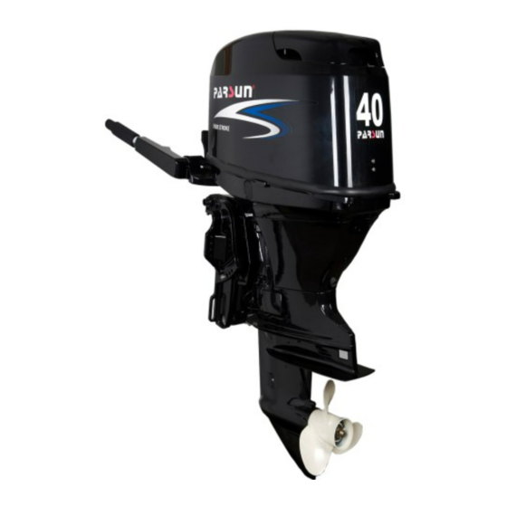
Summary of Contents for Parsun F30 BM
- Page 1 OUTBOARD MOTORS OWNER’S MANUAL F30/40 BM F30/40 FW / FW-T-EFI F30/40 BW / BW-T-EFI / BW-D-EFI SUZHOU PARSUN POWER MACHINE CO., LTD.
- Page 2 If there is any question concerning the manual, please consult your local PARSUN dealer. Data, illustrations or explanations in this Owner’s Manual do not constitute base for any legal claim against our company.
- Page 3 Engine Identification Numbers Outboard motor serial number The outboard motor serial number is marked on the label. The label can be found on the bracket left assembly or on the upper part of the bracket swivel. Record your outboard motor serial number in the spaces provided to assist you in ordering spare parts from your dealer or for reference in case your outboard motor is stolen.
- Page 4 Engine serial number The engine serial number is carved on the aluminum casting of engine. Engine serial number as follows:...
-
Page 5: Table Of Contents
Table of contents 1. Main components and General information ..................1 1.1 Main components ..........................1 1.2 General information ......................... 5 1.2.1Specification ..........................5 1.2.2 Fueling instruction ........................6 1.2.3 Propeller selection ........................8 2. Operation ............................8 2.1 Installation ............................8 2.1.1 Mounting height .......................... - Page 6 2.11.1 Tilting up ........................... 29 2.11.2 Tilting down ..........................30 2.12 Cruising in other conditions ......................31 2.12.1 Cruising in shallow water ......................31 2.12.2 Cruising in salt water ........................ 32 3. Maintenance ............................ 32 3.1 Greasing ............................33 3.2 Cleaning and adjusting spark plug ....................34 3.3 Checking the fuel system ......................
- Page 7 4.1 Transporting ..........................48 4.2 Storing ............................49 4.3 Flusher ............................51 5. Actions in emergency ........................52 5.1 Impact damage ..........................52 5.2 Power trim and tilt unit will not operate ..................53 5.3 Starter will not operate ........................54 5.4 Replacing fuse ..........................
-
Page 8: Main Components And General Information
1. Main components and General information 1.1 Main components 1.Top cowling 8. Tilt & trim rod 15.Throttle frication adjuster 2.Top cowling lock handle 9. Clamp bracket 16.Throttle grip 3.Drain screw 10.Tilt & trim button 17.Clam bolt 4.Anti-cavitation plate 11.Tiller handle 18.Stand bar 5.Trim-tab 12.Starters handle... - Page 9 A portable fuel tank includes parts as follows: 1. Fuel tank cap 3. Air vent screw 2. Fuel joint 4. Fuel gauge WARNING: The fuel tank supplier with this engine could only be used as supply of fuel for its running and must not be as a fuel storage container.
- Page 10 Remote control lever Moving the lever forward from the neutral position engages forward gear. Pulling the lever back from neutral engages reverse. The engine will continue to run at idle until the lever is moved about 35º (a detent can be felt). Moving the lever farther opens the throttle, and the engine will begin to accelerate. Neutral “N”...
- Page 11 NOTE: The neutral throttle lever will operate only when the remote control lever is in neutral. The remote control lever will operate only when the neutral throttle lever is in the closed position. 1. Fully open 2. Fully closed...
-
Page 12: General Information
1.2 General information 1.2.1Specification Main technical data: Items Data Items Data Type of engine Three cylinders,4-stroke Weight(BWL-D-EFI/BWS-D-EFI) 101.5Kg/99.9Kg Displacement 747cm Weight(FWL-T-EFI/FWS-T-EFI) 102.1Kg/100.5Kg Bore X stroke 65mm×75mm Recommended fuel Unleaded regular gasoline Gear ratio 2.0(26/13) Fuel tank capacity 1173mm(BM/BW) Overall length Recommended engine oil SAE10W30 or SAE10W40 768mm(FW) -
Page 13: Fueling Instruction
Main performance: Items Data Items Data Maximum output 29.4Kw/5500rpm Spark plug 18.0Nm Idling speed (in neutral, carburetor) 900±50rpm Propeller nut 35.0Nm Tightening torque Idling speed (in neutral, EFI) 800±50rpm for engine Engine oil drain bolt 27.0Nm Full throttle operating range 5000~6000rpm Engine oil filter 18.0Nm... - Page 14 Do not overfill the fuel tank. Take care not to spill gasoline, if gasoline spills, wipe it up immediately. Tighten the filler cap securely after refueling. If you should swallow some gasoline, inhale a lot of gasoline vapor, or get gasoline in your ...
-
Page 15: Propeller Selection
1.2.3 Propeller selection The performance of your outboard motor will be critically affected by your choice of propeller, as an incorrect choice could adversely affect performance. The outboard motor is fitted with propellers chosen to perform well over a range of applications, but there may be uses where a propeller with a different pitch would be more appropriate. - Page 16 NOTE: During water testing check the buoyancy of the boat, at rest, with its maximum load. Check that the static water level on the exhaust housing is low enough to prevent water entry into the power head, when water rises due to waves when the outboard is not running. WARNING:...
-
Page 17: Mounting Height
The optimum mounting height of the outboard motor is affected by the boat and motor combination and the desired use. Test runs at a different height can help determine the optimum mounting height. For further information, consult your “PARSUN” dealer or boat manufacturer. -
Page 18: Clamping The Outboard Motor
2.1.2 Clamping the outboard motor 1. Tighten the transom clamp screw evenly and securely. Occasionally check the clamp screws for tightness during operation of the outboard motor because they could become loose due to engine vibration. CAUTION: Outboards that use clamp bracket screws alone are INSUFFICIENT to properly and safely secure the outboard to the Transom. -
Page 19: Breaking In Engine
WARNING: Loose clamp screws could allow the outboard motor to fall off or move on the transom. This could cause loss of control. Make sure the clamp screws are tightened securely, occasionally check the screws for tightness during operation. 2. If the engine restraint cable attachment is equipped on your engine, an engine restraint cable or chain should be used. -
Page 20: Pre-Operation Checks
1. for the first hour of operation: Run the engine at 2000 r/min or at approximately half throttle. 2. for the second hour of operation: Run the engine at3000 r/min or at approximately three-quarter throttle. 3. for the next eight hours of operation: Avoid continuous operation at full throttle for more than five minutes at a time. - Page 21 ·Look for loose or damaged connections. ·Check operation of the starter and stop switches when the outboard motor is in the water. CAUTION ·Do not start the engine out of water. Overheating and serious engine damage can occur. ·Check the engine and engine mounting. ·Look for loose or damaged fasteners.
-
Page 22: Filling Fuel
1. Oil dipstick 2 Upper level mark 3.Lower level mark CAUTION Be sure to completely insert the dipstick into the dipstick guide. 2.4 Filling fuel WARNING: Gasoline and its vapors are highly flammable and explosive. Keep away from sparks, cigarettes, flames, or other sources of ignition. -
Page 23: Starting Engine
2.5 Starting engine 1. Connect fuel joints securely after loosing the air vent screw on the fuel tank cap (2 or 3 turns). 2. Connect fuel joints securely and squeeze the primer pump with the outlet end up until you feel it become firm (if equipped the fuel joint). - Page 24 3. Place the gear shift lever in neutral. NOTE: The start-in-gear protection device prevents the engine from starting except when in neutral. Attach the engine stop switch lanyard to secure place on your clothing, or your arm or leg. Then install the lock plate on the other end of the lanyard into the engine stop switch.
- Page 25 4. Place the throttle grip in the “START” position (manual start). Turn the main switch to “ON” (Electric start). NOTE: It is not necessary to use the choke when starting a warm engine. If the choke is left in the “START” (start) position while the engine is running, the engine will run poorly or stall.
- Page 26 5. Pull the manual starter handle slowly until you feel resistance. Then give a strong pull straight to crank and start the engine. Repeat if necessary. Turn the main switch to “START” (start), and hold it for a maximum or 5 seconds (Electric start). 6.
-
Page 27: Warm Up Engine
NOTE: Never turn the main switch to “START” (start) while the engine is running. Do not keep the starter motor turning for more than 5 seconds. If the starter motor is turned continuously for more than 5 seconds, the battery will be quickly discharged, thus making it impossible to start the engine. -
Page 28: Shifting
3. Check for steady flow of water from the cooling water pilot hole. CAUTION: · If water is not flowing out of the hole at all times while the engine is running, stop the engine and check whether the cooling water inlet on the lower case or the cooling water pilot hole is blocked. -
Page 29: Reverse
2. Move the gear shift lever quickly and firmly from neutral to forward. Pull up the neutral interlock rigger and move the remote control lever quickly and firmly from neutral to forward. (Remote control) 2.7.2 Reverse WARNING: When operating in reverse, go slowly. Do not open the throttle more than half. Otherwise the boat could become unstable, which could result in loss of control and an accident. -
Page 30: Tiller
2. Move the gear shift lever quickly and firmly from neutral to reverse. Check that the tilt lock lever is in the lock position. Pull up the neutral interlock rigger and move the remote control lever quickly and firmly from neutral to reverse. (Remote control) 2.8 Tiller 1. - Page 31 3. Throttle indicator The throttle indicator is on the throttle grip. The fuel consumption curve on the throttle indicator shows the relative amount of fuel consumed for each throttle position. Choose the setting that offers the best performance and fuel economy for the desired operation. 1.
-
Page 32: Trim Tab
WARNING: Do not over-tighten the friction adjuster. If there is too much resistance, it could be difficult to move throttle lever or grip, which could result in an accident. 2.9 Trim tab The trim tab should be adjusted so that the steering control can turned to either the right or left by applying same amount of force. - Page 33 1. Push and hold the engine stop button until the engine comes to a complete stop. NOTE: If the outboard motor is equipped with an engine stop switch lanyard, the engine can also be stopped by pulling the lanyard and removing the lock plate from the engine stop switch. 2.
-
Page 34: Trimming Outboard Motor
2.11 Trimming outboard motor There are 4 or 5 holes provided in the clamp bracket to adjust the outboard motor trim angle. 1. Stop the engine. 2. Remove the trim rod from the clamp bracket while slightly tilting the outboard motor up. 3. - Page 35 WARNING: Stop the engine before adjusting the trim angle. Use care to avoid being pinched when removing or installing the rod. Use caution when trying a trim position for the first time. Increase speed gradually and watch for any signs of instability or control problems.
-
Page 36: Tilting Up
2.11.1 Tilting up 1. Place the gear shift lever in neutral. Place the tilt lock lever (if equipped) in the up position. 3. Hold the rear handle and tilt the engine up fully until the tilt support lever automatically locks. For electric tilt model:... -
Page 37: Tilting Down
Press the “UP” switch to tilt the outboard motor up to the highest position, and push in the tilt support lever. 2.11.2 Tilting down 1. Slightly tilt the outboard motor up. 2. Pull out the tilt support lever, pull up the tilt lock lever, and slowly tilt the outboard motor down. For electric tilt model: Pull out the tilt support lever, press the “DN”... -
Page 38: Cruising In Other Conditions
3. Pull down the tilt lock lever when outboard moves down to the lowest position. (For manual tilt model) WARNING: Make sure the tilt & trim unit is in locked position when running the outboard (For manual tilt model) 2.12 Cruising in other conditions 2.12.1 Cruising in shallow water The outboard motor can be tilted up partially to allow operation in shallow water. -
Page 39: Cruising In Salt Water
CAUTION: The cooling water inlet on the lower unit should be not above the surface of the water when setting up for and cruising in shallow water. Otherwise severe damage from overheating can result. For tilting procedure, see section 2.11. 2.12.2 Cruising in salt water After operating in salt water, wash out the cooling water passages with fresh water to prevent them from becoming clogged with salt deposits. -
Page 40: Greasing
3.1 Greasing... -
Page 41: Cleaning And Adjusting Spark Plug
3.2 Cleaning and adjusting spark plug You should periodically remove and inspect the spark plug because heat and deposits will cause the spark plug to slowly break down and erode. If necessary, you should replace the spark plug with another of the correct type. Before fitting the spark plug, measure the electrode gap with a wire thickness gauge;... -
Page 42: Checking The Fuel System
3.3 Checking the fuel system 1. Check the fuel lines for leaks, crack, or malfunction. If a problem is found, your dealer or other qualified mechanic should repair it immediately. WARNING: Check for fuel leakage regularly. If any fuel leakage is found, the fuel system must be repaired by a qualified mechanic. ... -
Page 43: Cleaning The Fuel Filter
3.3.1 Cleaning the fuel filter 1. Remove the nut holding the fuel filter assembly if equipped. 2. Unscrew the filter cup, catching any spilled fuel in a rag. 3 . Remove the filter element, and wash it in solvent. Allow it to dry. Inspect the filter element and O-ring of the filter cup to make sure they are in good conditions. -
Page 44: Inspecting Idling Speed
4. Reinstall the filter element in the cup. Make sure the O-ring is in position in the cup. Firmly screw the cup onto the filter housing. 5. Attach the filter assembly to the bracket so that the fuel hoses are attached to the filter assembly. Run the engine and check the filter and lines for leaks. -
Page 45: Changing Engine Oil
3.5 Changing engine oil WARNING: Avoid draining the engine oil immediately after stopping the engine. The oil is hot and should be handled with care to avoid burns. Be sure the outboard motor is securely fastened to the transom or a stable stand. ... - Page 46 2. Prepare a suitable container that holds a larger amount than the engine oil capacity. Loosen and remove the drain screw while holding the container under the drain hole. Then remove the oil filler cap. Let oil drain completely. Wipe up any spilled oil immediately. 3.
-
Page 47: Checking Wiring And Connectors
3.6 Checking wiring and connectors Check that each grounding wire is properly secured and each connector is engaged securely. 3.7 Checking for leakage Check that no exhaust or water leaks from the joints between the exhaust cover, cylinder head and body cylinder. - Page 48 1. Check each of the propeller blades for wear, erosion from cavitation or ventilation, or other damage. 2. Check the propeller shaft for damage. 3. Check the splines’ shear pin for wear or damage. 4. Check for fish line tangled around the propeller shaft. 5.
-
Page 49: Removing The Propeller
3.8.1 Removing the propeller 1. Straighten the cotter pin and pull it out using a pair of pliers. 2. Remove the propeller nut, washer, and spacer (if equipped). 3. Remove the propeller and thrust washer. 1. Cotter pin 2.Nut 3.Washer 4.Propeller 5.Thrust washer 3.8.2 Installing the propeller CAUTION: Be sure to install the thrust washer before instating the propeller, otherwise the lower case and... -
Page 50: Changing Gear Oil
3.9 Changing gear oil WARNING: Be sure the outboard motor is securely fastened to the transom or a stable stand. Never get under the lower unit while the outboard motor is tilted, even when the tilt support lever or knob is locked. Serious injury could occur if the motor falls. 1. -
Page 51: Cleaning Fuel Tank
CAUTION: Inspect the used oil after it has been drained. If the oil is milky, water is getting into the gear case which can cause gear damage. Consult your dealer. 5. Use a flexible or pressurized filling device; inject the gear oil into the gear oil drain screw hole. (430cm )... -
Page 52: Checking And Replacing Anode(S)
5. Replace the gasket with a new one. Reinstall the fuel joint assembly and tighten the screws firmly. 3.11 Checking and replacing anode(s) Inspect the external anodes periodically. Remove scales from the surfaces of the anodes. Consult your dealer for replacement of external anodes. CAUTION: Do not paint anodes, as this would render them ineffective and can... -
Page 53: Maintenance Table
3.13 Maintenance Table When utilized under normal condition, maintained and repaired in the proper manner, the motor can work normally within the normal life period. The normal life of the engine is 350 hours or 10 years, whichever occurs first. Frequency of maintenance operations may be adjusted according to the operating conditions, but the following table gives general guidelines. - Page 54 Continuation /…1 Initial Every Item Operations 10 hours 50 hours 100 hours 200 hours ( 1 month ) ( 3 months ) ( 6 months ) ( 1 year ) ○ Shift link/shift cable Check/adjustment ○ Thermostat Check Throttle link/throttle ○...
-
Page 55: Transporting And Storing
4 Transporting and storing 4.1 Transporting The outboard motor should be trailed and stored in the normal running position. If there is insufficient road clearance in this position, then trailer the outboard motor in the tilt position using a motor support device. -
Page 56: Storing
Do not place the outboard motor on its side (not upright) before drain the engine oil completely, otherwise the oil would enter the cylinder and cause engine trouble. 4.2 Storing When store your outboard motor for prolonged periods of time (2 months or longer), several important procedures must be performed to prevent excessive damage. - Page 57 1. Lowest water level 2. Water surface CAUTION: If the fresh water level is below the level of the anti-cavitation plate, or if the water supply Is insufficient, engine seizure may occur. WARNING: Do not touch or remove electrical parts when starting or during the operation. ...
-
Page 58: Flusher
CAUTION: Store the fuel tank in a dry, well-ventilated place, not in direct sunlight. 4.3 Flusher Perform this procedure right after operation for thorough flushing. CAUTION: Do not perform this procedure while the engine is running. The water pump may be damaged from overheat, or serious damage can occur 1. -
Page 59: Actions In Emergency
3. Flush the fresh water through the cooling passage for about 15 minutes. Turn off the water and remove the water pipe connector. 4. Install the water pipe connector onto the water pipe plug after flushing. Tighten the nut. WARNING: Do not leave the water pipe connector loose on the bottom cowling water pipe plug or let the pipe hang free during normal operation. -
Page 60: Power Trim And Tilt Unit Will Not Operate
4. Have a dealer inspect the outboard motor before operating it again. 5.2 Power trim and tilt unit will not operate If the engine can not be tilted up or down with the power trim and tilt because of a discharged battery or a failure with the power trim and tilt unit, the engine can not be tilted manually. -
Page 61: Starter Will Not Operate
5.3 Starter will not operate If the starter mechanism does not operate, the engine can be started with an emergency starter rope. WARNING: Use this procedure only in an emergency and only to return to port for repairs. When the emergency starter rope is used to start the engine, the start-in-gear protection ... - Page 62 1.Start-in-gear protection cable 3. Remove the starter cover after removing the three bolts. Disconnect the leads for the warning indicator 4. Prepare the engine for starting. For further information, see section 2.5. 5. Insert the knotted end of the emergency starter rope into the notch in the flywheel rotor and wind the rope several turns around the flywheel clockwise.
-
Page 63: Replacing Fuse
7. Give a strong pull straight out to crank and start the engine. Repeat it necessary. 5.4 Replacing fuse If the fuse is burnt, select the correct ampere fuse to replace it from the accessory bag. WARNING: Make sure to use the correct fuse. The electric system will damage or fire could be caused if using the wrong fuse. - Page 64 5. Feed engine fogging oil or engine oil through the carburetor(s) and spark plug holes while starting the engine. 6. Take the outboard motor to a PARSUN dealer as soon as possible. CAUTION: Do not attempt to run the outboard motor until it has been completely inspected.
-
Page 65: Troubleshooting
6. Troubleshooting Trouble type Possible reason Recovery action Starter components are faulty Have serviced by your dealer Starter will not operate Shift level is not in neutral Shift to neutral Fuel tank is empty Fill tank with clean, fresh fuel Fuel is contaminated or stale Fill tank with clean, fresh fuel Clean or replace with recommended... - Page 66 Continuation /…1 Trouble type Possible reason Recovery action Check for pinched or kinked fuel line or Fuel system is obstructed other obstructions in fuel system Fuel is contaminated or stale Fill tank with clean, fresh fuel Clean or replace with recommended Fuel filter clogged type Spark plug gap is incorrect...
- Page 67 Continuation /…2 Trouble type Possible reason Recovery action Propeller is damaged Repair or replace propeller Adjust trim angle to achieve most efficient Trim angle is incorrect operation Motor is mounted at incorrect transom Adjust motor to proper transom height height Boat bottom is fouled with marine growth Clean boat bottom Weeds or other foreign matter are tangled...
- Page 68 Continuation /…3 Trouble type Possible reason Recovery action Thermostat is faulty or clogged Have serviced by your dealer Air vent screw on fuel tank is closed Open air vent screw Fuel pump has malfunctioned Have serviced by your dealer Engine power loss Fuel joint connection is incorrect Connect correctly Check and replace spark plug(s) as...
-
Page 69: Circuit Diagram
7. Circuit diagram F40BM 1: Spark plug 1 火花塞 2: Ignition coil 2 高压包 3: Enrich valve coil 3 加浓阀线圈 4: Enrich valve charge coil 4 加浓阀充电线圈 5 触发线圈 5: Impulse coil 6 充电线圈 6: Magneto coil 7 CDI点火模块 7: C.D.I. - Page 70 F40BW 1: Spark plug 1 火花塞 2: Ignition coil 2 高压包 3: Enrich valve coil 3 加浓阀线圈 4: Enrich valve charge coil 4 加浓阀充电线圈 5: Impulse coil 5 触发线圈 6: Magneto coil 6 充电线圈 7: C.D.I. unit 7 CDI点火模块 8: Oil pressure sensor 8 机油压力保护器...
- Page 71 F40BW-D 1 火花塞 2 高压包 3 加浓阀线圈 4 加浓阀充电线圈 5 触发线圈 6 充电线圈 7 CDI点火模块 8 机油压力保护器 9 信号灯组件 10 水温传感器 11 急停开关 12 照明线圈 13 整流调压器 14 保险丝 15 起动继电器 16 起动开关 17 空档开关 18 起动电机 19 电池 20 液压起翘继电器 21 液压起翘电机...
- Page 72 1: Spark plug 12: Lighting coil P/W: pink/white 2: Ignition coil 13: Rectifier pink G/W: green/white 3: Enrich valve coil 14: Fuse black L/W: blue/white Enrich valve charge coil Start relay green R/W: red/white 4: 15: 5: Impulse coil 16: Start switch white B/R:...
- Page 73 F40FW 1: Spark plug 2: Ignition coil 1 火花塞 2 高压包 3: Enrich valve coil 3 加浓阀线圈 4: Enrich valve charge coil 4 加浓阀充电线圈 5: Impulse coil 6: Magneto coil 5 触发线圈 6 充电线圈 7: C.D.I. unit 8: Oil pressure sensor 7 CDI点火模块...
- Page 74 Remote control box for FW 控制盒 Y/R: yellow/red Neutral switch 微动开关 红 yellow R/W: red/white Main switch 黄 点火开关 黄/红 发动机停止开关 blue black 红/白 Engine stop switch 蓝 蜂鸣器 绿 黑 green white Buzzer DESCRIPTION 棕 白 brown...
- Page 75 F40FW-T 1 火花塞 2 高压包 3 加浓阀线圈 4 加浓阀充电线圈 5 触发线圈 6 充电线圈 7 CDI点火模块 8 机油压力保护器 9 信号灯组件 10 水温传感器 11 急停开关 12 照明线圈 13 整流调压器 14 保险丝 15 起动继电器 16 起动电机 17 电池 18 10芯插头 19 液压起翘继电器 20 液压起翘电机 21 液压起翘开关(底罩)...
- Page 76 1: Spark plug 12: Lighting coil Y/R: yellow/red Ignition coil Rectifier pink P/W: pink/white 2: 13: 3: Enrich valve coil 14: Fuse black G/W: green/white 4: Enrich valve charge coil 15: Start relay green L/W: blue/white 5: Impulse coil 16: Start motor white R/W:...
- Page 77 Remote control box for F40FW-T 1: Power tilt&trim switch Start switch 2: 3: Engine stop switch P.T.T. switch Lg B Sb 4: Buzzer START Main switch Engine stop switch 5: Neutral switch Buzzer Neutral switch FREE DOWN pink black R :Red P : Pink green B : Black...
- Page 78 F40BW-EFI...
- Page 79 F40FW-EFI...
- Page 80 F40FW-EFI remote control box...
Need help?
Do you have a question about the F30 BM and is the answer not in the manual?
Questions and answers
Здравствуйте подскажите пожалуйста на новом моторе парсун 35 вепуск 2011г есть ограничители при обкатке чтобы не ушатать двигатель?
Yes, the Parsun F30 BM motor has a break-in procedure to prevent engine damage. It requires limited engine speeds and throttle settings during the first 10 hours of operation to allow proper wear-in of moving parts.
This answer is automatically generated