Renesas Synergy SK-S7G2 User Manual
S7g2 sk-s7g2 starter kit
Hide thumbs
Also See for Synergy SK-S7G2:
- Quick start manual (16 pages) ,
- Quick start manual (5 pages) ,
- User manual (29 pages)

Related Manuals for Renesas Synergy SK-S7G2


Summary of Contents for Renesas Synergy SK-S7G2
- Page 1 S7G2 SK-S7G2 STARTER KIT ANUAL Renesas Electronics America Rev 0.5 Sep 24, 2015 www.renesas.com...
- Page 2 The SK-S7G2 is not guaranteed to be error free, and the entire risk as to the results and performance of the SK-S7G2 is assumed by the User. The SK-S7G2 is provided by Renesas on an “as is” basis without warranty...
- Page 3 The user is advised to take ESD precautions when handling the equipment. • The Renesas SK-S7G2 does not represent and ideal reference design for an end product and does not fulfill the regulatory standards for an end product. R12UM0001EU0100 Rev 0.5...
-
Page 4: Table Of Contents
Synergy S7G2 SK-S7G2 Starter Kit User Manual Table of Contents Chapter 1 - Preface ............................... 1 Chapter 2 - Overview and Purpose..........................2 Purpose ............................... 2 In The Box ..............................2 Block Diagram ............................. 3 Hardware Features ............................3 Resources ..............................3 Chapter 3 - Getting Started ............................ - Page 5 Synergy S7G2 SK-S7G2 Starter Kit User Manual UART & CAN .............................. 19 Chapter 9 – Appendix A .............................. 20 Pin Connections............................20 Chapter 10 - Post Production Modifications ........................ 24 Chapter 11 - Additional Information ........................... 25 R12UM0001EU0100 Rev 0.5 Page 5 of Sep 24, 2015...
-
Page 6: Chapter 1 - Preface
*All brand or product names used in this manual are trademarks or registered trademarks of their respective companies or organizations. Copyright © 2015 Renesas Electronics America, Inc. All rights reserved. © 2015 Renesas Electronics Europe Ltd. All rights reserved. © 2015 Renesas Electronics Corporation. All rights reserved. -
Page 7: Chapter 2 - Overview And Purpose
Chapter 2 - Overview and Purpose 2.1 Purpose The SK-S7G2 is a Starter Kit for the Renesas Synergy S7G2 microcontroller in a 176 pin LQFP package. The board provides easy-to-access interfaces to the peripherals of the S7G2 microcontroller for application development. -
Page 8: Block Diagram
One capacitive slider Audio output QSPI memory (8MB) SPI, I2C, CAN, and SCI interface Bluetooth Smart (Low Energy) using a Renesas RL78/G1D Bluetooth Smart device 2.5 Resources The following documents are related to S7G2 and SK-S7G2 hardware: SK-S7G2 Quick Start Guide... -
Page 9: Chapter 3 - Getting Started
Synergy S7G2 SK-S7G2 Starter Kit User Manual Chapter 3 - Getting Started To start working with the SK-S7G2 Kit, see the Quick Start Guide included in the Kit. The Quick Start Guide provides instructions on how to download the required software tools and on how to use the tools to run a simple demonstration application, Blinky, on the board. -
Page 10: Chapter 4 - Power Supply Requirements
Synergy S7G2 SK-S7G2 Starter Kit User Manual Chapter 4 – Power Supply Requirements 4.1 Power Supply Power is supplied to the SK-S7G2 board through the debug USB connector (J19). The SK-S7G2 requires 5V applied on this interface (USB standard). Once power is supplied, the power supply indicator LED4 (green) will light up. 4.2 Power-Up Behavior When power is applied to the SK-S7G2, the power-on reset (POR) monitor of the S7G2 microcontroller resets the device. - Page 11 Synergy S7G2 SK-S7G2 Starter Kit User Manual Power consumption for the analog supply of the S7G2 microcontroller requires removing resistor R114 and measuring current across it. Figure 6: Measuring analog current consumption on S7G2 microcontroller R12UM0001EU0100 Rev 0.5 Page 6 of Sep 24, 2015...
-
Page 12: Chapter 5 - Board Components
Synergy S7G2 SK-S7G2 Starter Kit User Manual Chapter 5 – Board Components The main board components, interfaces, and configuration items are listed below. 5.1 On Board J-Link Debugger The SK-S7G2 board features a SEGGER J-Link On-Board debugger, accessible through J19 USB connector. Alternatively, the onboard debugger can be bypassed by removing resistors R107, R108, R109, and R110. -
Page 13: Ethernet
Synergy S7G2 SK-S7G2 Starter Kit User Manual Figure 9: Touch-screen controller 5.3 Ethernet The SK-S7G2 kit includes a Micrel KSZ8081 10/100 Ethernet physical interface. Ethernet connection is done via the RJ-45 standard connector J11. 5.4 PMOD The SK-S7G2 kit includes two standard PMOD interfaces. The first, PMODA, available on the J12 connector, exposes an SPI interface, three GPIO lines and an interrupt line to the S7G2 microcontroller. -
Page 14: Usb Device Port
Synergy S7G2 SK-S7G2 Starter Kit User Manual Figure 12: RS-232/485 and CAN interface 5.6 USB Device Port The SK-S7G2 kit is equipped with a USB Full-Speed (12Mbps) device port on J5. The SK-S7G2 cannot be powered via this interface (power still needs to be applied via the USB device port J19) but connection to this port can be detected since the power pin of this port is connected to a microcontroller GPIO. -
Page 15: Bluetooth
User Manual Figure 14: USB host port 5.8 Bluetooth The SK-S7G2 kit contains an on-board Bluetooth/BLE interface. This interface is implemented via a Renesas RL/78 Bluetooth SMART MCU. Communication with this Bluetooth Low Energy (BLE) interface is done via a serial communication interface (SCI) channel of the S7G2 MCU. -
Page 16: User Buttons And Leds
Synergy S7G2 SK-S7G2 Starter Kit User Manual Figure 17: Audio output 5.11 User Buttons and LEDs The SK-S7G2 kit includes two user buttons directly wired to interrupt pins of the S7G2 microcontroller, as well as three generic user LEDs connected to microcontroller GPIO pins. Figure 18: User buttons and LEDs 5.12 QSPI Flash The SK-S7G2 kit includes one 64Mb (8MB) QSPI Flash connected to the QSPI interface of the microcontroller. -
Page 17: Breakout Headers
Synergy S7G2 SK-S7G2 Starter Kit User Manual Figure 20: Arduino Shield interface 5.13 Breakout Headers All of the S7G2 microcontroller I/O pins are accessible via four double row 2.54mm (0.1”) pitch breakout headers (J20 through J23). Figure 21: S7G2 microcontroller breakout headers R12UM0001EU0100 Rev 0.5 Page 12 of Sep 24, 2015... -
Page 18: Chapter 6 - Board Layout
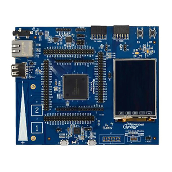
Synergy S7G2 SK-S7G2 Starter Kit User Manual Chapter 6 – Board Layout The SK-S7G2 kit board measures 145mm x 120mm and the following diagram shows the location of all the relevant board components described in the prior section. Figure 22: SK-S7G2 component placement R12UM0001EU0100 Rev 0.5 Page 13 of Sep 24, 2015... -
Page 19: Chapter 7 - Configuration
Synergy S7G2 SK-S7G2 Starter Kit User Manual Chapter 7 – Configuration The SK-S7G2 kit has several configuration options. These are set via jumpers. The following table lists the different jumpers and their positions. Table 1: SK-S7G2 configuration jumpers JUMPER FUNCTION S7G2 boot selection. - Page 20 Synergy S7G2 SK-S7G2 Starter Kit User Manual TTL interface on MCU breakout headers J20-J23 removed removed R12UM0001EU0100 Rev 0.5 Page 15 of Sep 24, 2015...
-
Page 21: Chapter 8 - Connectivity
Synergy S7G2 SK-S7G2 Starter Kit User Manual Chapter 8 – Connectivity The following sections describe in detail the interfaces available on the SK-S7G2 kit, detailing the MCU resources utilized in each. 8.1 USB Host Port The SK-S7G2 kit includes one USB Host/High-Speed port (J6). This port supplies current to devices connected to it via a current limited power switch (U14). -
Page 22: Lcd
Synergy S7G2 SK-S7G2 Starter Kit User Manual P806 ETH_RESET# P403 ETH_MDC P404 ETH_MDIO P705 ETH_CRS_DV P405 ETH_TXD_EN P700 ETH_TDX0 P406 ETH_TXD1 P702 ETH_RXD0 P703 ETH_RXD1 P704 ETH_RX_ER P701 ETH (Reference Clock) 8.4 LCD The SK-S7G2 kit includes a 240x320 QVGA LCD display with touch screen interface. This display is connected directly to the S7G2’s display port, and via a touchscreen controller IC to the display’s touchscreen interface. -
Page 23: Pmod
Synergy S7G2 SK-S7G2 Starter Kit User Manual P803 LCD_D1 P804 LCD_D0 P103 LCD_CS P102 LCD_SCK P115 LCD_WR P114 LCD_RD P101 LCD_MOSI P100 LCD_MISO Table 7: LCD touchscreen functions S7G2 Pin Function name P609 RESET# P004 IRQ9# P512 SCL2 P511 SDA2 8.4 PMOD The SK-S7G2 kit contains two PMOD ports, a PMODA port (J12), and a PMODB (J14). -
Page 24: Jtag/Swd
Synergy S7G2 SK-S7G2 Starter Kit User Manual P400 IRQ0# P603 GPIO (PMOD pin 4) P604 GPIO (PMOD pin 6) P605 GPIO (PMOD pin 8) 8.4 JTAG/SWD The SK-S7G2 kit includes several alternatives for JTAG emulation/debugging. It includes an onboard SEGGER J-Link JTAG debugger, accessible via the debugging/power USB port (J19). -
Page 25: Chapter 9 - Appendix A
Synergy S7G2 SK-S7G2 Starter Kit User Manual Chapter 9 – Appendix A 9.1 Pin Connections The following table shows the connection of S7G2 pins to SK-S7G2 functions. S7G2 Pin Peripheral Signal SK-S7G2 Connector P000 Arduino Shield AN000 J26 (1) P001 Arduino Shield AN001 J26 (2) - Page 26 Synergy S7G2 SK-S7G2 Starter Kit User Manual P300 JTAG TCK/SWCLK J18 (4) P301 Bluetooth / Arduino Shield RXD2 / RXD2 n/a / J27 (2) P302 Bluetooth / Arduino Shield TXD2 / TXD2 n/a / J27 (1) P303 Arduino Shield J27 (4) P304 Bluetooth RXD6_A...
- Page 27 Synergy S7G2 SK-S7G2 Starter Kit User Manual P506 Arduino Shield J24 (2) P507 Arduino Shield J24 (3) P511 LCD (Touchscreen) / Arduino Shield SDA2 / SDA2 n/a / J24 (9) P512 LCD (Touchscreen) / Arduino Shield SCL2 / SCL2 n/a / J24 (10) P600 User LED LED1...
- Page 28 Synergy S7G2 SK-S7G2 Starter Kit User Manual PA00 LCD_D5 J3 (26) PA01 LCD_D6 J3 (27) PA08 LCD_D9 J3 (30) PA09 LCD_D8 J3 (29) PA10 LCD_D7 J3 (28) PB00 USB Host USBH_VBUSEN PB01 USB Host USBHS_VBUS J6 (1) RESET JTAG RESET J18 (10) USBHS_N USB Host...
-
Page 29: Chapter 10 - Post Production Modifications
Synergy S7G2 SK-S7G2 Starter Kit User Manual Chapter 10 - Post Production Modifications None on v2.0 products. R12UM0001EU0100 Rev 0.5 Page 24 of Sep 24, 2015... -
Page 30: Chapter 11 - Additional Information
Synergy S7G2 SK-S7G2 Starter Kit User Manual Chapter 11 - Additional Information Further information available for this product can be found on the Renesas Synergy website at: http://am.renesas.com/products/embedded_systems_platform/synergy/ General information on Renesas Microcontrollers can be found on the global Renesas website: http://www.renesas.com/... - Page 31 Renesas Electronics America, Inc. 2801 Scott Boulevard Santa Clara, CA 95050-2554, US...
Need help?
Do you have a question about the Synergy SK-S7G2 and is the answer not in the manual?
Questions and answers