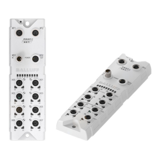
Balluff BNI PNT-508-055-P067 Installation Manual
Network interface
Hide thumbs
Also See for BNI PNT-508-055-P067:
- Installation manual (18 pages) ,
- User manual (84 pages)

Subscribe to Our Youtube Channel
Related Manuals for Balluff BNI PNT-508-055-P067


Summary of Contents for Balluff BNI PNT-508-055-P067
- Page 1 BNI PNT-508-055-P067 deutsch Montageanleitung english Installation guide français Notice de montage italiano Istruzioni di montaggio polski Instrukcja montażu...
- Page 2 Sicherheitsmaßnahmen treffen kann. Eine ausführliche Betriebsanleitung und weitere Informatio- Der Betreiber hat die Verantwortung, dass die örtlich nen zu diesem Produkt finden Sie unter www.balluff.com geltenden Sicherheitsvorschriften eingehalten werden. auf der Produktseite. Insbesondere muss der Betreiber Maßnahmen treffen, dass bei einem Defekt des Prokukts keine Gefahren für...
-
Page 3: Status Leds
BNI PNT-508-055-P067 Netzwerkschnittstelle Aufbau und Funktion Anzeigeelemente (Fortsetzung) FE-Anschluss Befestigungsloch Port/Pin-LEDs IO-Link-Port Anzeige Bedeutung Grün IO-Link-Verbindung aktiv PROFINET Port 1 PROFINET Port 2 Grün blin- Keine IO-Link-Verbindung oder falsches kend IO-Link-Device Grün schnell IO-Link: Preoperate während der Daten- blinkend haltung... -
Page 4: Einbau
über eine getrennte Stromquelle Elektrische Masse 0 V herstellen. I/O, C/Q Eingang / Ausgang (1 A / 2 A) / – Der IO-Link Master BNI PNT-508-055-P067 darf IO-Link beim Einsatz mit galvanisch getrennten Geräten n.c. Nicht verbunden wie z. B. BNI PNT-538-_05-Z063 nicht mit der gleichen Stromquelle versorgt werden. - Page 5 BNI PNT-508-055-P067 Netzwerkschnittstelle Elektrischer Anschluss (Fortsetzung) Erdung Um EMV-Störungen entge- genzuwirken, muss der Funktionserdungsanschluss verwendet werden. ► Erdungsanschluss mit der Funktionserde (FE) der Maschine verbinden. Der FE-Anschluss zwischen Gehäuse und Maschine muss eine niedrige Impedanz aufweisen und so kurz wie möglich sein.
- Page 6 BNI PNT-508-055-P067 Netzwerkschnittstelle UL-Anforderungen Spannungsversorgung Kabelgrößen Die Spannungsversorgung muss ein isolierter Typ oder ein Stromversorgungskabel: SELV-Typ sein. Gelistetes oder R/C-Kabel (CYJV2/8) mit M12-Innenge- winde und L-codiertem Stecker mit mindestens 24 V, Reinigung mindestens 16 A für alle Modelle. Mit S, SJ, SO, ST, SV...
-
Page 7: Network Interface
A comprehensive user’s guide and additional information The operator is responsible for ensuring that local safety about this product can be found at www.balluff.com on regulations are observed. the product page. In particular, the operator must take steps to ensure that a... - Page 8 BNI PNT-508-055-P067 Network interface Design and function Display elements (continued) FE connection Mounting hole Port/Pin LEDs IO-Link Port Display Meaning Green IO-Link connection active PROFINET Port 1 PROFINET Port 2 Flashing No IO-Link connection or incorrect green IO-Link device Green, fast...
-
Page 9: Installation
Signal Description actuator via a separate power source if possible. +24 V, 2 A – The IO-Link master BNI PNT-508-055-P067 must not be supplied with the same power Input / Output (1 A / 2 A / 4 A) source when used with galvanically isolated Electrical ground 0 V... - Page 10 BNI PNT-508-055-P067 Network interface Electrical connection (continued) Grounding To counteract EMC interference, the functional earth connection must be used. ► Connect the earth terminal to the functional earth (FE) of the machine. The FE connection between the housing and the machine must have a low impedance and be as short as possible.
- Page 11 BNI PNT-508-055-P067 Network interface UL requirements Power supply Cord Sizes Power In cord assembly: The power supply has to be an isolated type or SELV type. Listed or R/C (CYJV2/8) cord assembly with threaded Cleaning female M12 L-coded connector rated 24 V minimum, 16 A Clean the product only with dry cloth or cloth dampened minimum for all models.
-
Page 12: Interface Réseau
être mis hors service et protégé contre toute indications figurant dans les caractéristiques techniques, utilisation non autorisée. n’est garanti qu’avec les accessoires d’origine Balluff De façon générale, les modules BNI présentent une bonne appropriés ; l’utilisation d’autres composants entraîne la résistance aux produits chimiques et aux huiles. - Page 13 BNI PNT-508-055-P067 Interface réseau Structure et fonction Éléments d’affichage (suite) Connexion FE Trou de fixation LED Port/Broche port IO-Link Signal Signification Vert Liaison IO-Link active Vert clignotant Pas de liaison IO-Link ou mauvais Port PROFINET 1 Port PROFINET 2 appareil IO-Link Vert clignotant IO-Link : mode « preoperate »...
-
Page 14: Montage
– Le module IO-Link Master n.c. Non connecté BNI PNT-508-055-P067 ne doit pas être alimenté par la même source de courant Réglable à 1 A, 2 A et 4 A en tenant compte du courant total de 16 A et du courant total maximal de 4 A sur la broche GND du lorsqu'il est utilisé... - Page 15 BNI PNT-508-055-P067 Interface réseau Raccordement électrique (suite) Mise à la terre Pour contrer les interférences CEM, il convient d’utiliser la connexion de terre fonctionnelle. ► Relier la connexion de terre à la terre fonctionnelle (FE) de la machine. La connexion FE entre le boîtier et la machine doit présenter une faible impédance et être aussi courte...
-
Page 16: Alimentation Électrique
BNI PNT-508-055-P067 Interface réseau Exigences UL Alimentation électrique Sections des câbles Câble d’alimentation électrique : L’alimentation en tension doit être isolée ou du type SELV. Câble homologué ou R/C (CYJV2/8) avec connecteur mâle Nettoyage M12 à filetage intérieur et codage L avec au moins 24 V, Nettoyer le produit uniquement avec un chiffon sec ou un au moins 16 A pour tous les modèles. -
Page 17: Utilizzo Conforme
Balluff di tipo idoneo. L’utilizzo di altri componenti In linea generale, i moduli BNI hanno una buona resistenza comporta la decadenza della garanzia. - Page 18 BNI PNT-508-055-P067 Interfaccia di rete Struttura e funzionamento Elementi di visualizzazione (seguito) Collegamento FE Foro di fissaggio LED porte / LED pin, porta IO-Link Segnale Significato Verde Connessione IO-Link attiva Porta Profinet 1 Porta Profinet 2 Verde lampeggiante Connessione IO-Link assente,...
- Page 19 Ingresso / Uscita (1 A / 2 A / 4 A) corrente di sensore/bus ed attuatore tramite una fonte di alimentazione separata. Massa elettrica 0 V – Il master IO-Link BNI PNT-508-055-P067 non I/O, C/Q Ingresso / Uscita (1 A / 2 A) / IO-Link può essere alimentato con la stessa sorgente di n.c.
- Page 20 BNI PNT-508-055-P067 Interfaccia di rete Collegamento elettrico (seguito) Messa a terra Al fine di contrastare disturbi elettromagnetici, andrà utilizzato il collegamento di messa a terra funzionale. ► Allacciare il collegamento di messa a terra alla messa a terra funzionale (FE) della macchina.
- Page 21 BNI PNT-508-055-P067 Interfaccia di rete Requisiti UL Alimentazione di tensione Dimensioni dei cavi Cavo di alimentazione di corrente: L’alimentazione di tensione deve essere di tipo isolato o Cavo elencato o cavo R/C (CYJV2/8) con filettatura interna SELV. M12 e connettore con codifica L di minimo 24 V, almeno Pulizia 16 A per tutti i modelli.
- Page 22 Szczegółową instrukcję obsługi i dalsze informacje niebezpieczeństwa i podjąć odpowiednie środki dotyczące tego produktu znajdziesz na www.balluff.com bezpieczeństwa. na stronie produktu. Użytkownik ponosi odpowiedzialność za to, aby przestrzegane były lokalnie obowiązujące przepisy Użytkowanie zgodne z przeznaczeniem...
- Page 23 BNI PNT-508-055-P067 Złącze sieciowe Budowa i działanie Elementy wskazujące (ciąg dalszy) Przyłącze FE Otwór mocujący Diody LED portu/pinu port IO-Link Sygnał Znaczenie zielony połączenie IO-Link aktywne PROFINET port 1 PROFINET port 2 zielony brak połączenia IO-Link lub migający nieprawidłowe urządzenie IO-Link zielony szybko IO-Link: działanie wstępne podczas...
- Page 24 B. Można ustawić na 1 A, 2 A i 4 A uwzględniając łączny prąd 16 A i maksymalny łączny prąd 4 A na pinie GND portu BNI PNT-508-055-P067 nie może być zasilany z tego samego źródła zasilania. Cyfrowe wejścia czujnika, patrz wytyczne –...
- Page 25 BNI PNT-508-055-P067 Złącze sieciowe Podłączenie elektryczne (cd.) Uziemienie Aby zapobiegać zakłóceniom EMC, należy użyć funkcyjnego przyłącza uziemienia. ► Przyłącze uziemienia należy podłączyć z uziemieniem funkcyjnym (FE) maszyny. Przyłącze FE między obudową a maszyną musi mieć niską impedancję i być jak najkrótsze.
- Page 26 BNI PNT-508-055-P067 Złącze sieciowe Wymagania UL Napięcie zasilające Rozmiary kabli Kabel zasilający: Napięcie zasilania musi być typu izolowanego lub typu Wymieniony kabel lub kabel R/C (CYJV2 / 8) z gwintem SELV. wewnętrznym M12 i wtyczką z kodowaniem L o napięciu Czyszczenie co najmniej 24 V, co najmniej 16 A dla wszystkich modeli.
- Page 27 Americas Service Center Asia Pacific Service Center Poland Greater China Balluff Sp. z o.o. Balluff Inc. Balluff Automation (Shanghai) Co., Ltd. Ul. Graniczna 21A 8125 Holton Drive No. 800 Chengshan Rd, 8F, Building A, 54-516 Wrocław Florence, KY 41042 Yunding International Commercial Plaza...
Need help?
Do you have a question about the BNI PNT-508-055-P067 and is the answer not in the manual?
Questions and answers