Husqvarna K 1260 Workshop Manual
Hide thumbs
Also See for K 1260:
- Operator's manual (32 pages) ,
- Price list (48 pages) ,
- Operator's manual (36 pages)
Table of Contents
Advertisement
Advertisement
Table of Contents

Related Manuals for Husqvarna K 1260


Summary of Contents for Husqvarna K 1260
- Page 1 Workshop manual K 1260 HUSQVARNA CONSTRUCTION PRODUCTS...
-
Page 2: Table Of Contents
CONTENTS Page HUSQVARNA LITERATURE 2. MODELS K 1260 COMPONENTS – ORIENTATION 4. DISMANTLING INTO BASIC MODULES 5. STARTER 6. IGNITION SYSTEM 7. FLYWHEEL 8. AIR FILTER 9. INLET SYSTEM 10. FUEL SYSTEM 11. CARBURETTOR 12. DECOMPRESSION VALVE 13. CYLINDER/PISTON 14. CRANKCASE 15. -
Page 3: Literature
“Cutting head” (Example) Spares Spares K1260 IPL, K1260, K1260 RAIL, 2010-05, 576 13 90-01 The folder includes all spare parts for Husqvarna K1260 and the special model K1260 Rail. The folder contains complete exploded K1260 drawings for the whole machine where the... - Page 4 The Rail version is also available for blade diameters 14˝ (350 mm) and 16˝ (400 mm). The blade guard, belt pulleys and front belt guard are different for the 14 and 16 inch versions. K 1260 K 1260 Rail RA 10...
-
Page 5: Components - Orientation
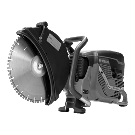
COMPONENTS – ORIENTATION Components 1. Cutting blade 2. Blade guard 3. Adjustment handle for the blade guard 4. Front handle 5. Air filter cover 6. Cylinder cover 7. Filler cap 8. Starter handle 9. Starter 10. Tool bracket with combination wrench 11. -
Page 6: Dismantling Into Basic Modules
DISMANTLING INTO BASIC MODULES Basic modules This chapter shows how the machine is built up of basic modules, for example, the starter, carburettor, air filter system, etc. The purpose is to illustrate how you can easily and effectively dismantle and assemble the machine in its basic modules. - Page 7 DISMANTLING INTO BASIC MODULES Cutting arm 1. Remove the nut and the three screws. 2. Lift off the cutting arm. Check when reassembling that the two pipe guides are in place. Air filter 1. Loosen the guard's three screws and remove the guard.
- Page 8 DISMANTLING INTO BASIC MODULES Inlet pipe The connection between the carburettor and the cylinder is flexible. Vibrations and heat transfer to the carburettor are minimised. 1. The rubber pipe is pushed onto the plastic frame which also serves as a hol- der of the throttle wire.
- Page 9 DISMANTLING INTO BASIC MODULES Anti-vibration Several service work operations can be facilitated by dividing the machine at the anti-vibration elements. The following must be done before dividing: – remove the air filter unit and cylinder cover – remove the starter –...
-
Page 10: Starter
STARTER Replacing the starter cord Dismantle the starter. Eliminate the spring force from the return spring 1. Pull out the starter cord approximately 12 in./30 cm. Hold the starter pulley with your thumb and place the cord in the cut-out on the starter pulley. 2. - Page 11 STARTER Return spring WARNING Handling of springs of this type means a high risk for eye and hand injuries, especially when dismantling a broken spring! Always wear safety goggles and gloves when handling the starter's return spring. Dismantling 1. Remove the centre screw. 2.
- Page 12 STARTER Starter pawls Function In principle the starter pawls have two positions that are determined by the centrifugal force generated by the rotation of the flywheel. When the engine is at a standstill the springs push the starter pawls towards the centre, which when starting then grip the starter pulley's metal sleeve.
-
Page 13: Ignition System
It is insensitive to moisture and dirt. The design is point such that the ignition point does not need to readjustment. Husqvarna K1260 has integrated overspeed protection in the electronic unit that limits the engine's speed to 9,300 rpm. - Page 14 IGNITION SYSTEM Trouble-shooting First check the ignition system if the engine will not start. Check the ignition spark Earth the spark plug to the cylinder. Put the stop button in operating position. Pull the starter handle as you would at start-up. Note that the plug can be examined without removing the cylinder cover.
- Page 15 IGNITION SYSTEM Test the short-circuit cable and stop switch Test using a measurement instrument or the following simple solution: Connect a battery in series with a test lamp to the short-circuit cable and engine body. Watch the test lamp while testing the function of the stop switch.
-
Page 16: Flywheel
502 51 49-02 The special tool is used for To remove the flywheel you need a special removing the flywheel. tool from Husqvarna. The tool fits all flywheels for Husqvarna power cutters. Fit the plate Fit the plate Centre the plate on the crank - Centre the plate on the crankshaft. - Page 17 FLYWHEEL Mount the screw press Press off the flywheel Press off the flywheel Lock the socket and screw in the Lock the outer socket with a wrench and centre screw. screw in the centre screw until the flyw- heel releases. Hint: If the flywheel is sitting very firm- ly, you can knock lightly with a hammer on the screw to the flywheel to release.
-
Page 18: Air Filter
AIR FILTER Function The centrifugal cleaning is the first step in the air purifi - cation of the inlet air. The fins on the flywheel supply the cylinder with cooling air (large arrow) while they are also the active part of the centrifugal cleaning of the engine's inlet air. -
Page 19: Inlet System
INLET SYSTEM Inlet system The inlet system is the connection between the air filter and cylinder with the intermediate carburettor. For engine function, it is essential that the inlet system closes tightly, to prevent dust from entering the engine and because the fuel/air mixture must always be correct. - Page 20 INLET SYSTEM SmartCarb™ The channel, marked by arrows, connects the carburettor's measurement chamber with inlet air in the inlet elbow. Pressure equalisation between these allows the carburettor to provide the right fuel/air mixture regardless of how fouled the filter may be. This is the operating principle of SmartCarb™. Make sure the gasket between the carburettor and inlet elbow is fitted with the hole facing the channel side in the inlet elbow.
-
Page 21: Fuel System
FUEL SYSTEM Fuel filter Fuel filter Dismantle the filler cap. Dismantle the filler cap and pull out the section holding the filler cap in position Catch the fuel hose with the when fuelling. help of tool 502 50 83-01. Catch the fuel hose with the help of tool 502 50 83-01. - Page 22 FUEL SYSTEM Check the fuel hose Check the fuel hose Plug the hose by the carburettor Detach the fuel hose at the carburettor and redo the pressure test. and plug the fuel hose. Repeat the pressure test. If pressure can build up the hose is intact and the carburettor must be checked.
- Page 23 FUEL SYSTEM Tank valve - function test The easiest way of testing the tank valve is by the “mouth method”. For hygiene reasons, fit a suitable hose on the valve. Test the tank valve by first sucking in the direction towards the tank – the air should slowly pass.
-
Page 24: Carburettor
CARBURETTOR Components 1. Throttle valve 2. Impulse channel, from crankcase to carburettor pump diaphragm 3. Screw for throttle wire play 4. Lever for throttle valve 5. Adjuster screw – high speed nozzle 6. Idling screw, speed adjustment 7. Measuring chamber cover 8. - Page 25 CARBURETTOR Functional test Functional test Pressure tester Pressure tester 501 56 27-01 501 56 27-01 The pressure tester has a pump piston The pressure tester is sup plied that is operated with one hand. with an adapter nipple for small The pressure tester is supplied with an sizes.
- Page 26 CARBURETTOR Measurement chamber Note the internal order of the parts when dismantling to avoid reassembling in the wrong order. Measurement chamber – function The measurement chamber has two chambers: The air chamber (towards the cover) and the fuel chamber (towards the carburettor body). These are separated by the measuring chamber diaphragm.
- Page 27 CARBURETTOR Pump unit Function The pump diaphragm (A) is driven by the pressure variations in the crankcase, which are led to the top of the pump diaphragm. The fuel on the underside of the diaphragm is pumped to the valves (B). The counter pressure of the measurement chamber diaphragm against the needle valve in the measurement chamber controls the valves' degree of opening and the quantity of fuel pumped into the measurement chamber's...
- Page 28 CARBURETTOR Throttle shafts Leakage at the throttle shafts will cause an incorrect fuel/air mixture and dust will penetrate the engine. Check that the throttle shafts have no radial gap. Damper shafts and seals can be replaced. If a gap in the throttle shafts occurs, you can assume that the carbu- rettor is badly worn and you should consider replacing the whole carburettor.
-
Page 29: Decompression Valve
DECOMPRESSION VALVE Decompression valve Function The decompression valve reduces the compression in the cylinder when starting. A limited quantity of fuel/air mixture leaks out through the decompression valve, as shown in fig. A. As soon as the engine fires the valve will close due to the combustion pressure, as in fig. -
Page 30: Cylinder/Piston
CYLINDER/PISTON Compression test Compression test The test indicates leakage from The compression test indicates leakage the combustion chamber. from the combustion chamber. If the Close the decompression machine lacks engine power and is diffi- valve or fit the sealing plug cult to start this may be due to poor 503 55 22-01. - Page 31 CYLINDER/PISTON Remove the cylinder base gasket. Remove the cylinder base gasket. Tool kit 502 50 70-01 Tool kit 502 50 70-01 The tool kit contains piston The tool kit contains, to the left, piston ring compressors, piston stop, ring compressors to compress the piston and base plate for the piston.
- Page 32 CYLINDER/PISTON Gudgeon pin punch Gudgeon pin punch 505 38 17-05 Used to dismantle and assemble The gudgeon pin punch is used to press the gudgeon pin. out the gudgeon pin. It is also used for assembly. 505 38 17-05 Dismantle the gudgeon pin Dismantle the gudgeon pin Push out the gudgeon pin by Push out the gudgeon pin in any direc-...
- Page 33 CYLINDER/PISTON Wear tolerances Wear tolerances Cylinder Cylinder Inspect the cylinder bore against Inspect the cylinder bore against the the light. As long as the surface light. As long as the surface layer has not layer has not been broken been broken through, the cylinder is in through, the cylinder is in working order.
- Page 34 The cause of engine failure is often difficult to establish, primarily when the machine's history is not known. The typical cases below can provide some guidance. (Pistons from Husqvarna K760.) Normal wear Typical normal wear is easiest to see on the piston sections that face the exhaust and inlet sides.
- Page 35 CYLINDER/PISTON Assembly Assembly Oil in Oil in New or cleaned bearings and piston rings should be oiled in with 2-stroke oil before assembly to initially ensure satisfactory lubrication. The arrow pointing The arrow pointing towards the towards the exhaust port exhaust port Important to turn the arrow The piston is not symmetrical.
-
Page 36: Crankcase
CRANKCASE Leakage test A leaking crankcase results in reduced crankcase compression. A typical sign is that the machine is difficult to start. Tools 502 71 38-01 502 71 39-01 Tools 502 71 39-01 and 506 34 45-01 are required during the leakage test to seal the exhaust port and inlet port. - Page 37 CRANKCASE Crankcase seal Tools In order to change the crankcase sealing rings, you will need puller 502 50 55-01, assembly wedge 502 50 52-01 and assem- bly punch 502 50 82-01. 502 50 55-01 502 50 52-01 502 50 82-01 Dismantling 1.
- Page 38 Tools Tools A universal puller (504 90 90-02) and a A universal puller and a special special tool (grip plate) from Husqvarna tool are needed to split the (544 06 00-02) are needed to spilt the crankcase. crankcase. 504 90 90-02...
- Page 39 CRANKCASE If the bearing releases from the crankcase 531 00 48-67 Normally the bearing should release from the crankshaft during dismantling. The bearing is dismantled from the crankshaft using the puller 531 00 48-67. 1. First fit the puller plate behind the bearing.
- Page 40 CRANKCASE Crankshaft Tools The tool kit 544 10 36-02 is used to press in the crankshaft in the bearings. Threaded fittings are available for the clutch and flywheel, M12V and M10x1. Assembly Picture 1. Attach the crankcase half in a vice with soft jaws.
-
Page 41: Clutch
CLUTCH Dismantling Dismantling Dismantle the cutting head, the Dismantle the cutting head, the rear belt rear belt guard, the air filter guard, the air filter cover, and the filter cover, and the filter base. base. Fit the piston stop Fit the piston stop Lock the crankshaft's travel by fitting the piston stop 504 91 06-05 instead of the spark plug. - Page 42 CLUTCH Clutch springs Dismantling Secure the clutch in a vice. Place a large screwdriver against the spring hook. Knock the screwdriver with your hand to release the spring hook and avoid rehooking. Push out the spring hook using a pin punch.
- Page 43 CLUTCH Bearing replacement – needle bearings A clutch drum with needle bearings has been the standard design on Husqvarna petrol-powered cutters for a long time. The needle bearing is lubricated through a channel in the crankshaft from the crankcase. Tools Replacing the needle bearing is most easily done by using a hydraulic press.
-
Page 44: Cutting Head
CUTTING HEAD Dismantling – blade Dismantling – blade guard guard/bearing housing /bearing housing Dismantle the cutting head Dismantle the cutting head from the from the machine. machine. This chapter describes dismantling of the cutting head components and has instructions for replacing the blade shaft bearing at the end. - Page 45 CUTTING HEAD Assembly – blade Assembly – blade guard guard/bearing housing /bearing housing Make sure the rubber seal has Make sure the rubber seal has the right the right fit. fit in relation to the bearing housing and blade guard. Turn the bearing housing so that the screw holes are accessi- Turn the bearing housing so that the...
- Page 46 CUTTING HEAD Belt pulley Belt pulley Dismantling Dismantling Lock the belt pulley with a pin Attach the bearing holder in a vice with punch and remove the centre soft jaws. Lock the belt pulley rotation screw. with a pin punch or a screwdriver. Remove the centre screw.
- Page 47 CUTTING HEAD Blade shaft bearing housing K1260 and K1260 Rail have different bearing housings for the blade shaft. The location of the actual bearings and shaft and bearings, however, is identical for both bearing housings. The same method and tools are used for changing the bearings in the two bearing housings.
- Page 48 CUTTING HEAD Fitting with press Fitting with press Push down the first bearing Support the bearing housing under the fully to the stop in the bearing area for the bearing with, for example, a housing. piece of wood so that the bearing housing is horizontal.
-
Page 49: Wet System
WET SYSTEM Wet system Design A spray nozzle is located on each side of the blade guard. The water strikes a section of the cutting blade and the centrifugal force carries it out towards the blade's diamond segment. The spray nozzles are available with several different hole diameters depen- ding on the type of machine and application. -
Page 50: Handle
HANDLE Rear handle - control The handle unit is permanently attached to the fuel tank. This chapter deals with maintenance work on the rear handle control. Maintenance work related to the fuel tank is described in the “Fuel system” chapter. Work on the anti-vibration elements is described on Page 9. In some of the pictures in this section, the rear handle has been divided to show the assembly of the components. - Page 51 HANDLE Throttle lock Press in the throttle in the handle top. Press the throttle forwards with a screwdriver and lift up the rear edge. Pull the throttle from the handle. Removed throttle lock. Important If the white lever for the throttle wire is not included, as shown below, it can be pressed with a screwdriver as shown in the adjacent pictures.
- Page 52 HANDLE 5. Fit the shaft from the right side of the machine, as seen from behind. Knock in the shaft with a pin punch and a small hammer. Fit the throttle lock 1. Position the spring loop in the slot for this in the throttle, as shown in the divided handle to the right.
-
Page 53: Tools
502 51 49-02 Pressure tester Flywheel puller Kit consisting of pump with Puller for the flywheel. Fits all pressure gauge and nozzles, hose petrol-driven Husqvarna cutters. and sealing plug for universal use. Dismantling the flywheel. ● ● Leakage testing the crankcase. - Page 54 TOOLS ● = Service action 503 55 22-01 544 10 36-02 Sealing plug Bearing press Replaces the decompression valve. Dismantling the main bearing. ● ● Leakage testing the crankcase. ● Assembly of the crankshaft. ● Assembly of the clutch's support washer on the crank shaft.
- Page 55 www.husqvarnacp.com 115 54 49-26 English 2012-10...
Need help?
Do you have a question about the K 1260 and is the answer not in the manual?
Questions and answers