Table of Contents
Advertisement
Quick Links
Advertisement
Table of Contents

Related Manuals for DFI NP951-B16C


Summary of Contents for DFI NP951-B16C
- Page 1 NP951-B16C System Board User’s Manual 935-NP9511-000G A11000927...
-
Page 2: Copyright
Copyright This publication contains information that is protected by copyright. No part of it may be reproduced in any form or by any means or used to make any transfor- mation/adaptation without the prior written permission from the copyright hold- ers. -
Page 3: Fcc And Doc Statement On Class B
FCC and DOC Statement on Class B This equipment has been tested and found to comply with the limits for a Class B digital device, pursuant to Part 15 of the FCC rules. These limits are designed to provide reasonable protection against harmful interference when the equipment is operated in a residential installation. -
Page 4: Table Of Contents
Introduction Table of Contents Copyright ................... 2 Trademarks ..................2 FCC and DOC Statement on Class B ..........3 About this Manual ................7 Warranty ..................7 Static Electricity Precautions ............. 8 Safety Measures ................. 8 About the Package ................9 Before Using the System Board ............ - Page 5 Introduction I/O Connectors ................35 S/PDIF Connector ..............35 LVDS LCD Panel Connector and LCD/Inverter Power Connector ..36 Digital I/O Connector ..............38 SATA (Serial ATA) Connectors ............ 39 Cooling Fan Connector .............. 40 Front Audio Connector .............. 41 Front Panel Connector ..............
- Page 6 Introduction Adobe Acrobat Reader 7.0 (English Version) ......121 Installing the AHCI Driver During Windows XP Installation ..123 Appendix A - Watchdog Timer ............124 Appendix B - System Error Message ..........127 Appendix C - Troubleshooting ............129...
-
Page 7: About This Manual
Introduction About this Manual An electronic file of this manual is included in the CD. To view the user’s manual in the CD, insert the CD into a CD-ROM drive. The autorun screen (Main Board Utility CD) will appear. Click “User’s Manual” on the main menu. Warranty 1. -
Page 8: Static Electricity Precautions
Introduction Static Electricity Precautions It is quite easy to inadvertently damage your PC, system board, components or devices even before installing them in your system unit. Static electrical dis- charge can damage computer components without causing any signs of physical damage. -
Page 9: About The Package
Introduction About the Package The system board package contains the following items. If any of these items are missing or damaged, please contact your dealer or sales representative for as- sistance. One system board One USB cable One Serial ATA data cable ... -
Page 10: Chapter 1 - Introduction
Introduction Chapter 1 - Introduction Specifications Processor • Intel Atom N270 (Diamondville SC) processor ® • 1.6GHz core frequency, 1.10V voltage • 2.5W thermal design power • 512KB on-die second level cache • 533-MT/s FSB • 22x22 mm, 1.0 mm ball pitch and 437 balls FCBGA Chipset • Intel chipset ® - Northbridge: Intel 945GSE GMCH ® - Southbridge: Intel 82801GBM ICH7M ® System Memory • One 200-pin DDR2 SODIMM socket (1.8V) • Maximum memory supports up to 2GB • Supports 400MHz and 533MHz DDR2 SDRAM Expansion Slots • 1 mini PCI slot Graphics... - Page 11 Introduction • 1 CompactFlash socket I/O Connectors • 2 connectors for 4 additional external USB 2.0/1.1 ports • 1 connector for an additional external serial port (RS232/ RS422/RS485 selectable) • 1 LVDS LCD panel connector • 1 LCD/inverter power connector • 1 DIO connector • 1 front audio connector for line-out and mic-in jacks • 1 S/PDIF connector • 1 Serial ATA connector • 1 4-pin power connector for SATA drive • 1 front panel connector • 1 fan connector • Award BIOS BIOS • 8Mbit SPI interface BIOS • Supports ACPI specification 2.0/1.0 Energy Efficient • Supports ACPI STR (Suspend to RAM) function Design • Wake-On-Events include: - Wake-On-PS/2 Keyboard/Mouse - Wake up by mini PCI card - Wake-On-LAN - USB KB/MS wake up from S3 - Wake-On-Ring...
-
Page 12: Features
Introduction Features Watchdog Timer The Watchdog Timer function allows your application to regularly “clear” the sys- tem at the set time interval. If the system hangs or fails to function, it will reset at the set time interval so that your system will continue to operate. CompactFlash The system board is equipped with the CompactFlash socket for inserting a... - Page 13 Introduction Gigabit LAN The Realtek RTL8111C PCI Express Gigabit controller supports up to 1Gbps data transmission. The system board supports USB 2.0 and USB 1.1 ports. USB 1.1 supports 12Mb/ second bandwidth while USB 2.0 supports 480Mb/second bandwidth providing a marked improvement in device transfer speeds between your computer and a wide range of simultaneously accessible external Plug and Play peripherals.
- Page 14 Introduction Wake-On-USB This function allows you to use a USB keyboard or USB mouse to wake up a sys- tem from the S3 (STR - Suspend To RAM) state. Important: If you are using the Wake-On-USB Keyboard/Mouse function for 2 USB ports, the 5V_standby power source of your power supply must support ≥1.5A. For 3 or more USB ports, the 5V_standby power source of your power supply must support ≥2A.
-
Page 15: Chapter 2 - Hardware Installation
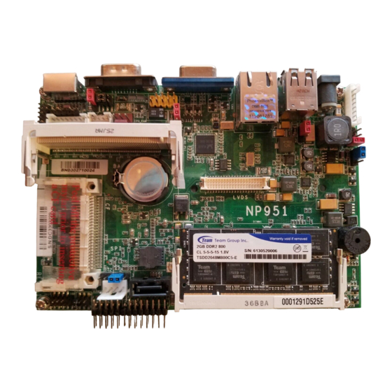
Hardware Installation Chapter 2 - Hardware Installation System Board Layout Power-on select (JP5) LCD/Inverter power Panel power select (J8) DC-IN 12V ATX +12V power (optional) USB 0-1 power select (JP4) USB 0 USB 1 Standby LED Realtek RTL 8111C LVDS LCD panel USB 2-3 power select (JP3) USB 2-3... - Page 16 Hardware Installation Intel Atom N270 Intel 945GSE Intel ICH7M Realtek Winbond ALC262 W83627 Solder Side...
-
Page 17: System Memory
Hardware Installation Important: Electrostatic discharge (ESD) can damage your system board, processor, disk drives, add-in boards, and other components. Perform the upgrade instruction procedures described at an ESD workstation only. If such a station is not available, you can provide some ESD protection by wearing an antistatic wrist strap and attaching it to a metal part of the system chassis. -
Page 18: Installing The Dim Module
Hardware Installation Installing the SODIMM DDR2 Module 1. Make sure the PC and all other peripheral devices connected to it has been powered down. 2. Disconnect all power cords and cables. 3. Locate the SODIMM socket on the board. 4. Note the key on the socket. The key ensures the module can be plugged into the socket in only one way. - Page 19 Hardware Installation 6. To seat the module into the socket, apply firm even pressure to each end of the module until it slips down into the socket. The contact fingers on the edge of the module will almost completely disappear inside the socket. Note: The board used in the following illustrations may not resemble the actual one.
-
Page 20: Jumper Settings
Hardware Installation Jumper Settings Clear CMOS Data 1-2 On: Normal 2-3 On: (default) Clear CMOS Data If you encounter the following, a) CMOS data becomes corrupted. b) You forgot the supervisor or user password. you can reconfigure the system with the default values stored in the ROM BIOS. To load the default values stored in the ROM BIOS, please follow the steps below. -
Page 21: Ps/2 Power Select
Hardware Installation PS/2 Power Select 1-2 On: 5V 2-3 On: (default) 5V_standby JP1 is used to select the power of the PS/2 keyboard/mouse port. Selecting 5V_standby will allow you to use the PS/2 keyboard or PS/2 mouse to wake up the system. -
Page 22: Usb Power Select
Hardware Installation USB Power Select USB 0-1 (JP4) 1-2 On: 5V 2-3 On: (default) 5V_standby USB 2-3 (JP3) JP3 (for USB 2-3) and JP4 (for USB 0-1) are used to select the power of the USB ports. Selecting 5V_standby will allow you to use a USB device to wake up the system. -
Page 23: Panel Power Select
Hardware Installation Panel Power Select 5-6 On: 3.3V 1-2 On: 12V 3-4 On: 5V (default) J8 is used to select the power supplied to the LCD panel. Important: Before powering-on the system, make sure J8’s setting matches the LCD panel’s specification. Selecting the incorrect voltage will seriously dam- age the LCD panel. -
Page 24: Com 2 Rs232/Rs422/Rs485 Select
Hardware Installation COM 2 RS232/RS422/RS485 Select COM 2 JP9 is used to configure COM 2 to RS232, RS422 (Full Duplex) or RS485. The pin function of COM 2 will vary according to the jumper’s setting. 5-6 On: RS485 3-4 On: RS422 1-2 On: RS232 Full Duplex (default) -
Page 25: Com 1 Rs232/Power Select
Hardware Installation COM 1 RS232/Power Select COM 1 1-3, 2-4 On: 3-5, 4-6 On: RS232 standard RS232 with (default) 5V/12V power COM 1 1 2 3 4 5 1 2 3 4 5 6 7 8 9 6 7 8 9... -
Page 26: Power-On Select
Hardware Installation Power-on Select 1-2 On: 2-3 On: Power-on via Power-on via power button AC power (default) JP5 is used to select the method of powering on the system. If you want the system to power-on whenever AC power comes in, set JP5 pins 2 and 3 to On. If you want to use the power button, set pins 1 and 2 to On. -
Page 27: Rear Panel I/O Ports
Hardware Installation Rear Panel I/O Ports USB 1 DC-in USB 0 COM 1 PS/2 The rear panel I/O ports consist of the following: • DC-in 12V • 2 USB ports • LAN port • VGA port • COM 1 port • PS/2 port... -
Page 28: Dc-In 12V / Optional 4-Pin Atx 12V Power
Hardware Installation DC-in 12V / Optional 4-pin ATX 12V Power DC-in 12V +12V Ground Ground +12V ATX 12V Power (optional) DC-in 12V This jack provides maximum of 60W power and is considered a low power solu- tion. Connect a DC power cord to this jack. Use a power adapter with 16V-22V DC output voltage. Using a voltage higher than the recommended one may fail to boot the system or cause damage to the system board. -
Page 29: Usb Ports
Hardware Installation USB Ports USB 1 10 9 USB 0 N. C. +Data +Data -Data -Data -Data -Data +Data +Data USB 4-5 N. C. USB 2-3 USB allows data exchange between your computer and a wide range of simulta- neously accessible external Plug and Play peripherals. The system board is equipped with two onboard USB 2.0/1.1 ports (USB 0-1). The two 10-pin connectors allow you to connect 4 additional USB 2.0/1.1 ports. - Page 30 Hardware Installation Wake-On-USB Keyboard/Mouse (USB 0-1 and USB 2-3 only) The Wake-On-USB Keyboard/Mouse function allows you to use a USB keyboard or USB mouse to wake up a system from the S3 (STR - Suspend To RAM) state. To use this function: • Jumper Setting JP3 and/or JP4 must be set to “2-3 On: 5V_standby”. Refer to “USB Power Select” in this chapter for more information.
-
Page 31: Lan Port
Hardware Installation LAN Port The LAN port allows the system board to connect to a local area network by means of a network hub. BIOS Setting Configure the onboard LAN in the Integrated Peripherals submenu (“Onboard De- vice” section) of the BIOS. Refer to chapter 3 for more information. Driver Installation Install the LAN drivers. Refer to chapter 4 for more information. -
Page 32: Vga Port
Hardware Installation VGA Port The VGA port is used for connecting a VGA monitor. Connect the monitor’s 15-pin D-shell cable connector to the VGA port. After you plug the monitor’s cable con- nector into the VGA port, gently tighten the cable screws to hold the connector in place. BIOS Setting Configure the onboard VGA in the Advanced Chipset Features submenu of the BIOS. Refer to chapter 3 for more information. -
Page 33: Com (Serial) Ports
Hardware Installation COM (Serial) Ports 1 2 3 4 5 6 7 8 9 COM 1 COM 2 COM 1 is fixed at RS232. COM 2’s pin definition will vary according to JP9’s settings. Refer to “COM 2 RS232/RS422/RS485 Select” in this chapter for more information. The serial ports are asynchronous communication ports with 16C550A-compatible UARTs that can be used with modems, serial printers, remote display terminals, and other serial devices. -
Page 34: Ps/2 Port
Hardware Installation PS/2 Port The PS/2 port is used to connect a PS/2 keyboard and a PS/2 mouse by means of the provided cable. PS/2 keyboard port PS/2 mouse port Connect to the board’s PS/2 port Important: Make sure to turn off your computer prior to connecting or disconnecting a mouse or keyboard. Failure to do so may damage the system board. -
Page 35: I/O Connectors
Hardware Installation I/O Connectors S/PDIF Connector SPDIF out Ground SPDIF in The S/PDIF connector is used to connect an external S/PDIF port. Your S/PDIF port may be mounted on a card-edge bracket. Install the card-edge bracket to an available slot at the rear of the system chassis then connect the audio cable to the S/PDIF connector. Make sure pin 1 of the audio cable is aligned with pin 1 of the S/PDIF connector. -
Page 36: Lvds Lcd Panel Connector And Lcd/Inverter Power Connector
Hardware Installation LVDS LCD Panel Connector LCD/Inverter Power Connector LCD/Inverter power LVDS LCD panel The system board allows you to connect a LCD Display Panel by means of the LVDS LCD panel connector and the LCD/Inverter power connector. These connec- tors transmit video signals and power from the system board to the LCD Display Panel. - Page 37 Hardware Installation LVDS LCD Panel Connector Pins Pins Function Function N. C. N. C. N. C. N. C. LVDS_Out2+ LVDS_Out6+ LVDS_Out2- LVDS_Out6- LVDS_Out1+ LVDS_Out5+ LVDS_Out1- LVDS_Out5- LVDS_Out0+ LVDS_Out4+ LVDS_Out0- LVDS_Out4- LVDS_CLK1+ LVDS_CLK2+ LVDS_CLK1- LVDS_CLK2- LVDS_DDCCLK N. C. LVDS_DDCDAA N. C. Panel Power Panel Power Panel Power Panel Power LCD/Inverter Power Connector Pins Function Panel Inverter Brightness Voltage Control...
-
Page 38: Digital I/O Connector
Hardware Installation Digital I/O Connector +12V Ground 5VSB Digital I/O power Digital I/O The Digital I/O connector provides powering-on function to an external device that is connected to this connector. Digital I/O Connector Pins Function DIO0 DIO1 DIO2 DIO3 DIO4 DIO5 DIO6 DIO7... -
Page 39: Sata (Serial Ata) Connectors
Hardware Installation SATA (Serial ATA) Connector Ground Ground SATA 1 +12V Peripheral power The Serial ATA connector is used to connect a Serial ATA device. Connecting a SATA Device The system board package comes with a Serial ATA data cable. Connect one end of the cable to SATA 1 and the other end to your Serial ATA device. The system board package also comes with a power cable that must be connect- ed to the system board’s peripheral power connector and the SATA drive’s power connector in order to provide power to the drive. -
Page 40: Cooling Fan Connector
Hardware Installation Cooling Fan Connector Sense Power Ground The fan connector is used to connect a cooling fan. The cooling fan will provide adequate airflow throughout the chassis to prevent overheating the CPU and sys- tem board components. BIOS Setting The PC Health Status submenu of the BIOS will display the current speed of the cooling fan. Refer to chapter 3 for more information. -
Page 41: Front Audio Connector
Hardware Installation Front Audio Connector The front audio connector allows you to connect line-out and mic-in jacks. Driver Installation Install the audio driver. Refer to chapter 4 for more information. -
Page 42: Front Panel Connector
Hardware Installation Front Panel Connector 12 11 PWR-BTN RESET-SW HDD-LED PWR-LED Front panel HDD-LED - HDD LED This LED will light when the hard drive is being accessed. RESET SW - Reset Switch This switch allows you to reboot without having to power off the system. PWR-BTN - Power Switch This switch is used to power on or off the system. PWR-LED - Power/Standby LED When the system’s power is on, this LED will light. When the system is in the S1 (POS - Power On Suspend) state, it will blink every second. When the system is in the S3 (STR - Suspend To RAM) state, it will blink every 4 seconds. -
Page 43: Expansion Slot
Hardware Installation Expansion Slot Mini PCI The Mini PCI slot is used to install a Mini PCI card. Mini PCI card is a small form factor PCI card with the same signal protocol, electrical definitions, and configu- ration definitions as the conventional PCI. -
Page 44: Battery
Hardware Installation Battery Battery The lithium ion battery powers the real-time clock and CMOS memory. It is an auxiliary source of power when the main power is shut off. Safety Measures • Danger of explosion if battery incorrectly replaced. • Replace only with the same or equivalent type recommend by the manufac- turer. • Dispose of used batteries according to local ordinance. -
Page 45: Compactflash Socket
Hardware Installation CompactFlash Socket CompactFlash socket The CompactFlash socket is used for inserting a CompactFlash card. Compact- Flash card is a small removable mass storage device designed with flash tech- nology - a non-volatile storage solution that does not require a battery to retain data indefinitely. The CompactFlash technology is widely used in products such as portable and desktop computers, digital cameras, handheld data collection scanners, PDAs, Pocket PCs, handy terminals and personal communicators. -
Page 46: Chapter 3 - Bios Setup
BIOS Setup Chapter 3 - BIOS Setup Award BIOS Setup Utility The Basic Input/Output System (BIOS) is a program that takes care of the ba- sic level of communication between the processor and peripherals. In addition, the BIOS also contains codes for various advanced features found in this system board. -
Page 47: Standard Cmos Features
BIOS Setup Standard CMOS Features Use the arrow keys to highlight “Standard CMOS Features” and press <Enter>. A screen similar to the one below will appear. Phoenix - AwardBIOS CMOS Setup Utility Standard CMOS Features Fri, Jul 3 2009 Date <mm:dd:yy> Item Help Time <hh:mm:ss>... - Page 48 BIOS Setup IDE Channel 0 Master to IDE Channel 1 Slave To configure the IDE drives, move the cursor to a field then press <Enter>. The following screen will appear. Phoenix - AwardBIOS CMOS Setup Utility IDE Channel 0 Master Press Enter Item Help IDE HDD Auto-Detection...
- Page 49 BIOS Setup Head This field displays the number of read/write heads. Precomp This field displays the number of cylinders at which to change the write tim- ing. Landing Zone This field displays the number of cylinders specified as the landing zone for the read/write heads.
- Page 50 BIOS Setup Base Memory Displays the amount of base (or conventional) memory installed in the system. The value of the base memory is typically 512K for systems with 512K memory installed on the motherboard or 640K for systems with 640K or more memory installed on the motherboard.
-
Page 51: Advanced Bios Features
BIOS Setup Advanced BIOS Features The Advanced BIOS Features allows you to configure your system for basic op- eration. Some entries are defaults required by the system board, while others, if enabled, will improve the performance of your system or let you set some fea- tures according to your preference. - Page 52 BIOS Setup CPU Feature This field is used to configure the CPU that is installed on the system board. Move the cursor to this field then press <Enter>. Phoenix - AwardBIOS CMOS Setup Utility CPU Feature Item Help Delay Prior to Thermal 16 Min Limit CPUID MaxVal Disabled...
- Page 53 BIOS Setup Hard Disk Boot Priority This field is used to select the boot sequence of the hard drives. Move the cursor to this field then press <Enter>. Use the Up or Down arrow keys to select a de- vice then press <+> to move it up or <-> to move it down the list. Phoenix - AwardBIOS CMOS Setup Utility Hard Disk Boot Priority 1.
- Page 54 BIOS Setup Quick Power On Self Test This field speeds up Power On Self Test (POST) after you power on the system. When Enabled, the BIOS will shorten or skip some check items during POST. First Boot Device, Second Boot Device, Third Boot Device and Boot Other Device Select the drive to boot first, second and third in the “First Boot Device”...
- Page 55 BIOS Setup Typematic Rate (Chars/Sec) This field allows you to select the rate at which the keys are accelerated. Typematic Delay (Msec) This field allows you to select the delay between when the key was first de- pressed and when the acceleration begins. Security Option This field determines when the system will prompt for the password - everytime the system boots or only when you enter the BIOS setup.
-
Page 56: Advanced Chipset Features
BIOS Setup Advanced Chipset Features Phoenix - AwardBIOS CMOS Setup Utility Advanced Chipset Features By SPD DRAM Timing Selectable Item Help x CAS Latency Time Auto Menu Level Auto x DRAM RAS# to CAS# Delay x DRAM RAS# Precharge Auto Auto x Precharge Delay (tRAS) - Page 57 BIOS Setup CAS Latency Time This field is used to select the local memory clock periods. DRAM RAS# to CAS# Delay This field is used to select the latency between the DRAM active command and the read/write command. DRAM RAS# Precharge This field is used to select the idle clocks after issuing a precharge command to the DRAM.
- Page 58 BIOS Setup PCI Express Root Port Func Phoenix - AwardBIOS CMOS Setup Utility PCI Express Root Port Func PCI Express Port 1 Auto Item Help v1.0a PCI-E Compliancy Mode Menu Level : Move Enter: Select +/-/PU/PD: Value F10: Save ESC: Exit F1: General Help ↑↓→←...
- Page 59 BIOS Setup Boot Display This field is used to select the type of display to use when the system boots. Select this option if you want the system to boot the CRT display. LVDS Select this option if you want the system to boot the LCD flat panel display. CRT+LVDS Select this option if you want the system to boot both the CRT and LCD flat panel display.
-
Page 60: Integrated Peripherals
BIOS Setup Integrated Peripherals Phoenix - AwardBIOS CMOS Setup Utility Integrated Peripherals Press Enter Item Help OnChip IDE Device Press Enter Onboard Device Menu Level Press Enter Super IO Device : Move Enter: Select +/-/PU/PD: Value F10: Save ESC: Exit F1: General Help... - Page 61 BIOS Setup IDE HDD Block Mode Enabled The IDE HDD uses the block mode. The system BIOS will check the hard disk drive for the maximum block size the system can transfer. The block size will depend on the type of hard disk drive. Disabled The IDE HDD uses the standard mode.
- Page 62 BIOS Setup On-Chip Serial ATA Disabled Disables the onboard SATA. Auto The system will detect the existing SATA and IDE drives then automatically set them to the available master/slave mode. Combined Mode This option allows you to combine both IDE and SATA drives; supporting maximum of 2 drives on each channel.
- Page 63 BIOS Setup Onboard Device Move the cursor to this field and press <Enter>. The following screen will appear. Phoenix - AwardBIOS CMOS Setup Utility Onboard Device Enabled Onboard LAN1 Control Item Help Onboard PXE ROM Control Disabled Menu Level Azalia Audio Control Enabled ...
- Page 64 BIOS Setup USB Device Setting Move the cursor to this field and press <Enter>. The following screen will ap- pear. Phoenix - AwardBIOS CMOS Setup Utility USB Device Setting USB 1.0 Controller Disabled Item Help x USB 2.0 Controller Disabled Menu Level x USB Operation Mode Full/Low Speed...
- Page 65 BIOS Setup USB Mouse Function Due to the limited space of the BIOS ROM, the support for legacy USB mouse (in DOS mode) is by default set to Disabled. With more BIOS ROM space available, it will be able to support more advanced features as well as provide compatibility to a wide variety of peripheral devices.
- Page 66 BIOS Setup Super IO Device Move the cursor to this field and press <Enter>. The following screen will appear. Phoenix - AwardBIOS CMOS Setup Utility Super IO Device Power On Function BUTTON ONLY Item Help x Hot Key Power ON Ctrl-F1 Menu Level Onboard Serial Port 1...
- Page 67 BIOS Setup Hot Key Power On This field is used to select a function key that you would like to use to pow- er-on the system. Onboard Serial Port 1 and Onboard Serial Port 2 3F8/IRQ4, 2F8/IRQ3, 3E8/IRQ4, 2E8/IRQ3 Allows you to manually select an I/O address for the serial port. Disabled Disables the serial port.
-
Page 68: Power Management Setup
BIOS Setup Power Management Setup The Power Management Setup allows you to configure your system to most ef- fectively save energy. Phoenix - AwardBIOS CMOS Setup Utility Power Management Setup Enabled ACPI Function Item Help ACPI Suspend Type S3(STR) Menu Level Instant-Off Soft-Off By PWR-BTTN ... - Page 69 BIOS Setup Soft-Off by PWR-BTTN This field allows you to select the method of powering off your system. Delay 4 Sec. Regardless of whether the Power Management function is enabled or disabled, if the power button is pushed and released in less than 4 sec, the system en- ters the Suspend mode.
- Page 70 BIOS Setup Date (of Month) Alarm The system will power-on everyday according to the time set in the “Time (hh:mm:ss) Alarm” field. 1-31 Select a date you would like the system to power-on. The system will power- on on the set date, and time set in the “Time (hh:mm:ss) Alarm” field. Time (hh:mm:ss) Alarm This is used to set the time you would like the system to power-on.
-
Page 71: Pnp/Pci Configurations
BIOS Setup PnP/PCI Configurations This section shows how to configure the PCI bus system. It covers some very technical items and it is strongly recommended that only experienced users should make any changes to the default settings. Phoenix - AwardBIOS CMOS Setup Utility PnP/PCI Configurations Init Display First Onboard... - Page 72 BIOS Setup IRQ Resources Move the cursor to this field and press <Enter>. Set each system interrupt to either PCI Device or Reserved. Phoenix - AwardBIOS CMOS Setup Utility IRQ Resources IRQ-3 assigned to PCI Device Item Help IRQ-4 assigned to PCI Device Menu Level IRQ-5 assigned to...
-
Page 73: Pc Health Status
BIOS Setup PC Health Status Phoenix - AwardBIOS CMOS Setup Utility PC Health Status Case Open Warning Disabled Item Help Shutdown Temperature Disabled Menu Level Current System Temperature C/104 Current CPU Temperature C/102 CPU Fan Speed 0 RPM Vcore 0.90V 5.17V 1.05V... - Page 74 BIOS Setup CPU Fan Tolerance Value This field is used to select the tolerance value of the CPU’s temperature. The op- tions are 1, 2, 3, 4 and 5. If you selected 3, it allows the temperature to run 3 degrees higher or lower.
-
Page 75: Frequency/Voltage Control
BIOS Setup Frequency/Voltage Control Phoenix - AwardBIOS CMOS Setup Utility Frequency/Voltage Control Spread Spectrum Disabled Item Help Menu Level : Move Enter: Select +/-/PU/PD: Value F10: Save ESC: Exit F1: General Help ↑↓→← F5: Previous Values F6: Fail-Safe Defaults F7: Optimized Defaults The settings on the screen are for reference only. -
Page 76: Load Fail-Safe Defaults
BIOS Setup Load Fail-Safe Defaults The “Load Fail-Safe Defaults” option loads the troubleshooting default values per- manently stored in the ROM chips. These settings are not optimal and turn off all high performance features. You should use these values only if you have hard- ware problems. -
Page 77: Load Optimized Defaults
BIOS Setup Load Optimized Defaults The “Load Optimized Defaults” option loads optimized settings from the BIOS ROM. Use the default values as standard values for your system. Highlight this option in the main menu and press <Enter>. Phoenix - AwardBIOS CMOS Setup Utility Frequency/Voltage Control Standard CMOS Features ... -
Page 78: Set Supervisor Password
BIOS Setup Set Supervisor Password If you want to protect your system and setup from unauthorized entry, set a supervisor’s password with the “System” option selected in the Advanced BIOS Features. If you want to protect access to setup only, but not your system, set a supervisor’s password with the “Setup”... -
Page 79: Set User Password
BIOS Setup Set User Password If you want another user to have access only to your system but not to setup, set a user’s password with the “System” option selected in the Advanced BIOS Features. If you want a user to enter a password when trying to access setup, set a user’s password with the “Setup”... -
Page 80: Save & Exit Setup
BIOS Setup Save & Exit Setup When all the changes have been made, highlight “Save & Exit Setup” and press <Enter>. Phoenix - AwardBIOS CMOS Setup Utility Standard CMOS Features Frequency/Voltage Control Advanced BIOS Features Load Fail-Safe Defaults ... -
Page 81: Exit Without Saving
BIOS Setup Exit Without Saving When you do not want to save the changes you have made, highlight “Exit With- out Saving” and press <Enter>. Phoenix - AwardBIOS CMOS Setup Utility Standard CMOS Features Frequency/Voltage Control Advanced BIOS Features Load Fail-Safe Defaults ... -
Page 82: Updating The Bios
BIOS Setup Updating the BIOS To update the BIOS, you will need the new BIOS file and a flash utility, AWD- FLASH.EXE. Please contact technical support or your sales representative for the files. 1. Save the new BIOS file along with the flash utility AWDFLASH.EXE to a floppy disk. - Page 83 BIOS Setup 6. The following will appear. Do You Want to Save BIOS (Y/N) This question refers to the current existing BIOS in your system. We recom- mend that you save the current BIOS and its flash utility; just in case you need to reinstall the BIOS.
-
Page 84: Chapter 4 - Supported Software
Supported Software Chapter 4 - Supported Software The CD that came with the system board contains drivers, utilities and software applications required to enhance the performance of the system board. Insert the CD into a CD-ROM drive. The autorun screen (Mainboard Utility CD) will appear. -
Page 85: Drivers For Windows Vista System
Supported Software Drivers for Windows Vista System Intel Chipset Software Installation Utility The Intel Chipset Software Installation Utility is used for updating Windows INF files so that the Intel chipset can be recognized and configured properly in the system. To install the utility, click “Intel Chipset Software Installation Utility”... - Page 86 Supported Software 3. Go through the readme d o c u m e n t f o r s y s t e m requirements and installa- tion tips then click Next. 4. Setup is now installing the driver. Click Next to continue.
-
Page 87: Intel Graphics Drivers
Supported Software Intel Graphics Drivers To install the utility, click “Intel Graphics Drivers” on the main menu. 1. Setup is now ready to install the graphics driver. Click Next. 2. Read the license agreement then click Yes. - Page 88 Supported Software 3. Go through the readme d o c u m e n t f o r s y s t e m requirements and installa- tion tips then click Next. 4. Setup is now installing the driver. Click Next to continue.
-
Page 89: Audio Drivers
Supported Software Audio Drivers To install the utility, click “Audio Drivers” on the main menu. 1. Setup is extracting the files needed to install the driver. 2. Click Next to start the installation. 3. Setup is configuring the new software installation. - Page 90 Supported Software 4. C l i c k “ Ye s , I wa n t t o restart my computer now” then click Finish. Restarting the system will allow the new software installation to take effect.
-
Page 91: Lan Drivers
Supported Software LAN Drivers To install the driver, click “LAN Drivers” on the main menu. 1. Setup is now ready to install the driver. Click Next. 2. C l i c k I n s t a l l b e g i n installation. - Page 92 Supported Software 3. After completing instal- lation, click Finish to exit setup.
-
Page 93: Hardware Monitor For Windows
Supported Software Hardware Monitor for Windows The system board comes with the Hardware Monitor for Windows utility. This utility is capable of monitoring the system’s temperature, fan speed, voltage, etc. and allows you to manually set a range (Highest and Lowest Limit) to the items being monitored. - Page 94 Supported Software 3. Click Next to install or click Browse to select another folder. 4. C l i c k N e x t t o a d d t h e p r o g r a m i c o n t h e Program Folder.
- Page 95 Supported Software 6. Click Yes if you want to create a Hardware Doctor shortcut at your desktop. 7. Click “Yes, I want to restart my computer now” then click Finish. Restarting the system will allow the utility to take effect.
- Page 96 Supported Software Using the Hardware Monitor for Windows Utility 1. When you try to run the utility, which is usually done by double-clicking the Hardware Doctor short- cut, an error message will appear. 2. To solve this problem, right- click the Hardware Doc- tor shortcut.
- Page 97 Supported Software 4. You can now access the utility.
-
Page 98: Intel Matrix Storage Manager Utility
Supported Software Intel Matrix Storage Manager Utility Intel Matrix Storage Manager is a utility that allows you to monitor the current status of the SATA drives. It enables enhanced performance and power manage- ment for the storage subsystem. Note: This utility is supported only when the SATA Mode field is set to AHCI. (The SATA Mode field is in the OnChip IDE Device section, Integrated Peripherals submenu of the BIOS utility.) To install the utility, click “Intel Matrix Storage Manager Utility”... - Page 99 Supported Software 3. Read the license agreement then click Yes. 4. Go through the readme d o c u m e n t f o r s y s t e m requirements and installa- tion tips then click Next. 5.
-
Page 100: Installing The Ahci Driver During Windows Vista Installation
Supported Software Installing the AHCI Driver During Windows Vista Installation The AHCI driver must be installed during Windows Vista installation. This is ® required in order to install the operating system onto a hard drive when in AHCI mode. 1. Start Windows Setup by booting from the installation CD. - Page 101 Supported Software 4. The screen on the right will appear. Select the driver.
-
Page 102: Creating An Ahci Driver Floppy Diskette Under Vista
Supported Software Creating an AHCI Driver Floppy Diskette under Vista The system board package includes floppy diskettes which are needed when you install the AHCI driver during Windows Vista installation. If in any case you lost the diskette, you can create another one by following the steps below. 1. -
Page 103: Adobe Acrobat Reader 7.0 (English Version)
Supported Software Adobe Acrobat Reader 7.0 (English Version) To install, click “Adobe Acrobat Reader 7.0 (English Version)” on the main menu. 1. Click Next to continue. 2. Setup is now ready to in- stall. Click Next. 3. Click Next to install or click Change Destination Folder to select another folder. - Page 104 Supported Software 4. Click Install to begin instal- lation. 5. Click Finish to exit instal- laion.
-
Page 105: Drivers For Windows Xp System
Supported Software Drivers for Windows XP System Microsoft DirectX 9.0C Driver To install the utility, click “Microsoft DirectX 9.0C Driver” on the main menu. 1. C l i c k “ I a c c e p t t h e agreement”... - Page 106 Supported Software 3. Click Finish. Reboot the system for DirectX to take effect.
-
Page 107: Intel Chipset Software Installation Utility
Supported Software Intel Chipset Software Installation Utility The Intel Chipset Software Installation Utility is used for updating Windows INF files so that the Intel chipset can be recognized and configured properly in the system. To install the utility, click “Intel Chipset Software Installation Utility” on the main menu. 1. - Page 108 Supported Software 3. Go through the readme d o c u m e n t f o r s y s t e m requirements and installa- tion tips then click Next. 4. Setup is now installing the driver. Click Next to continue.
-
Page 109: Intel Graphics Drivers
Supported Software Intel Graphics Drivers To install the utility, click “Intel Graphics Drivers” on the main menu. 1. To start installation, click Next. 2. Setup is now ready to install the graphics driver. Click Next. 3. Read the license agreement then click Yes. - Page 110 Supported Software 4. Go through the readme d o c u m e n t f o r s y s t e m requirements and installa- tion tips then click Next. 5. Setup is now installing the driver. Click Next to continue.
-
Page 111: Audio Drivers
Supported Software Audio Drivers To install the utility, click “Audio Drivers” on the main menu. 1. Setup is extracting the files needed to install the driver. 2. Click Next to start the installation. 3. Setup is configuring the new software installation. - Page 112 Supported Software 4. C l i c k “ Ye s , I wa n t t o restart my computer now” then click Finish. Restarting the system will allow the new software installation to take effect.
-
Page 113: Lan Drivers
Supported Software LAN Drivers To install the driver, click “LAN Drivers” on the main menu. 1. Setup is now ready to install the driver. Click Next. 2. Click Install to begin instal- lation. - Page 114 Supported Software 3. After completing instal- lation, click Finish to exit setup.
-
Page 115: Hardware Monitor For Windows
Supported Software Hardware Monitor for Windows The system board comes with the Hardware Monitor for Windows utility. This utility is capable of monitoring the system’s temperature, fan speed, voltage, etc. and allows you to manually set a range (Highest and Lowest Limit) to the items being monitored. - Page 116 Supported Software 3. C l i c k N e x t t o a d d t h e p r o g r a m i c o n t h e Program Folder. 4. After completing instal- lation, click Finish to exit setup.
- Page 117 Supported Software 6. Click “Yes, I want to restart my computer now” then click Finish. Restarting the system will allow the driver to take effect.
-
Page 118: Intel Matrix Storage Manager Utility
Supported Software Intel Matrix Storage Manager Utility Intel Matrix Storage Manager is a utility that allows you to monitor the current status of the SATA drives. It enables enhanced performance and power manage- ment for the storage subsystem. Note: This utility is supported only when the SATA Mode field is set to AHCI. (The SATA Mode field is in the OnChip IDE Device section, Integrated Peripherals submenu of the BIOS utility.) To install the utility, click “Intel Matrix Storage Manager Utility”... - Page 119 Supported Software 3. Read the license agreement then click Yes. 4. Go through the readme d o c u m e n t f o r s y s t e m requirements and installa- tion tips then click Next. 5.
-
Page 120: Ahci For F6 During Windows Setup Floppy Driver
Supported Software AHCI for F6 During Windows Setup Floppy Driver This is used to create a floppy driver diskette needed when you install Windows ® XP using the F6 installation method. This will allow you to install the operating system onto a hard drive when in AHCI mode. Click “AHCI for F6 During Windows Setup Floppy Driver”... -
Page 121: Adobe Acrobat Reader 7.0 (English Version)
Supported Software Adobe Acrobat Reader 7.0 To install the reader, click “Adobe Acrobat Reader 7.0” on the main menu. 1. Click Next to continue. 2. Setup is now ready to in- stall. Click Next. - Page 122 Supported Software 3. Click Next to install or click Change Destination Folder to select another folder. 4. Click Install to begin instal- lation. 5. Click Finish to exit instal- laion.
-
Page 123: Installing The Ahci Driver During Windows Xp Installation
Supported Software Installing the AHCI Driver During Windows XP Installation The AHCI driver must be installed during the Windows XP installation using the ® F6 installation method. This is required in order to install the operating system onto a hard drive when in AHCI mode. 1. -
Page 124: Appendix A - Watchdog Timer
Watchdog Timer Appendix A - Watchdog Timer Watchdog Timer The following parameters are references for setting the time interval of the Watchdog Timer function. The system will regularly be “cleared” according to the set time interval. If the system hangs or fails to function, it will also reset ac- cording to the time interval so that your system will continue to operate. - Page 125 Watchdog Timer mSuperio_Get_Reg Macro RegIndex dx, SuperIo_CFG_Port al, RegIndex dx, al NEWIODELAY dx, SuperIo_DAT_Port al, dx NEWIODELAY endM mSuperio_LDN_Select Macro mSuperio_Set_Reg 07h, LDN endM mSuperio_Set_Reg Macro RegIndex, SetValue dx, SuperIo_CFG_Port al, RegIndex dx, al NEWIODELAY dx, SuperIo_DAT_Port al, SetValue dx, al NEWIODELAY endM NEWIODELAY...
- Page 126 Watchdog Timer mSuperio_Enter_Config mSuperio_LDN_Select 08h ; PLED mode register, WDTO time unit as second, Keyboard reset when WDTO time out mSuperio_GetSet_Reg 0F5h, 11110111b, 00000100b ; , Disable MS/KB interrupt reset WDTO counting, IRQ2 for WDTO mSuperio_GetSet_Reg 0F7h, 11111111b, 11000010b ; , WDTO Time out Value mSuperio_Set_Reg 0F6h, WDT_Counter mSuperio_Exit_Config W83627Hx_WDT...
-
Page 127: Appendix B - System Error Message
System Error Message Appendix B - System Error Message When the BIOS encounters an error that requires the user to correct something, either a beep code will sound or a message will be displayed in a box in the mid- dle of the screen and the message, PRESS F1 TO CONTINUE, CTRL-ALT-ESC or DEL TO ENTER SETUP, will be shown in the information box at the bottom. - Page 128 System Error Message Hard Disk(s) fail (20) HDD initialization error. Hard Disk(s) fail (10) Unable to recalibrate fixed disk. Hard Disk(s) fail (08) Sector Verify failed. Keyboard is locked out - Unlock the key The BIOS detects that the keyboard is locked. Keyboard controller is pulled low. Keyboard error or no keyboard present Cannot initialize the keyboard.
-
Page 129: Appendix C - Troubleshooting
Troubleshooting Appendix C - Troubleshooting Troubleshooting Checklist This chapter of the manual is designed to help you with problems that you may encounter with your personal computer. To efficiently troubleshoot your system, treat each problem individually. This is to ensure an accurate diagnosis of the problem in case a problem has multiple causes. - Page 130 Troubleshooting The picture seems to be constantly moving. 1. The monitor has lost its vertical sync. Adjust the monitor’s vertical sync. 2. Move away any objects, such as another monitor or fan, that may be creating a magnetic field around the display. 3.
- Page 131 Troubleshooting Hard Drive Hard disk failure. 1. Make sure the correct drive type for the hard disk drive has been entered in the BIOS. 2. If the system is configured with two hard drives, make sure the bootable (first) hard drive is configured as Master and the second hard drive is config- ured as Slave.
- Page 132 Troubleshooting System Board 1. Make sure the add-in card is seated securely in the expansion slot. If the add-in card is loose, power off the system, re-install the card and power up the system. 2. Check the jumper settings to ensure that the jumpers are properly set. 3.
Need help?
Do you have a question about the NP951-B16C and is the answer not in the manual?
Questions and answers