Table of Contents
Advertisement
Quick Links
VISIT VIKINGPUMP.COM FOR PDF OF CURRENT TSM ISSUE & TO VIEW REPAIR VIDEOS
TECHNICAL SERVICE MANUAL: INSTALLATION, OPERATION & MAINTENANCE
TABLE OF CONTENTS
Model Number Chart .....................................................................1
General Information .......................................................................1
Safety Information & Instructions ................................................2
Tools Required For Disassembly / Assembly .............................3
Normal Operation ...........................................................................3
Pump Characteristics ......................................................................................... 3
General ............................................................................................4
10 Pumping Principal................................................................................. 4
®
10 Range Operating Parameters .............................................................. 4
®
Equipment Serial Number .................................................................................. 4
Installation ......................................................................................5
Startup Checklist ................................................................................................. 6
Cleaning & Wet-End Maintenance ...............................................7
Cleaning ................................................................................................................ 7
Rotor Retainer Seal Replacement Procedure .....................................................7
Cleaning Procedure for Circumferential Rotor Shaft Threads ............................7
Preventive Maintenance ..................................................................................... 7
Annual Maintenance ........................................................................................... 8
Remanufacturing Program ...................................................................................8
Disassembly & Assembly: Pump Head & Seal ...........................9
Pump Head Disassembly ................................................................................... 9
Seal Disassembly ................................................................................................ 9
Single O-Ring ......................................................................................................9
Double O-Ring ....................................................................................................9
Single Mechanical Seal .................................................................................... 10
Double Mechanical Seal .................................................................................. 10
Seal Assembly ...................................................................................................10
Single O-Ring ................................................................................................... 10
Double O-Ring ................................................................................................. 10
Single Mechanical Seal .................................................................................... 10
Double Mechanical Seal .................................................................................. 10
Seal Flush Installation ...................................................................................... 11
Pump Head Assembly .......................................................................................11
Disassembly & Assembly: Gear Box ......................................... 11
Gear Box Disassembly .....................................................................................11
Gear Box Assembly ...........................................................................................12
Specifications ...............................................................................13
Standard Clearances .........................................................................................13
Pressure Limitation of Port Types ...................................................................15
10 Exploded View .....................................................................................16
®
Fasteners & Torque Settings ...........................................................................17
Care Of Stainless Steel .....................................................................................18
ASTM A-494 ........................................................................................................18
Elastomer Seal Replacement Following Passivation ...................................18
Troubleshooting Guide .....................................................................................19
For ATEX Pumps Only .................................................................20
ATEX Equipment Groups .................................................................................20
ATEX Tag Used On Viking Pump ATEX Certified Pumps .............................20
Risk Assessment ...............................................................................................21
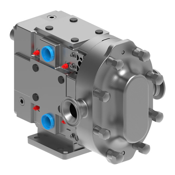
FIGURE 1
CIRCUMFERENTIAL PISTON PRODUCT LINE:
STAINLESS STEEL
TRA
10 SERIES
®
SIZES: ALL
© 2024 Viking Pump, Inc. • Cedar Falls, IA
MODEL NUMBER CHART
Standard Models:
• 0060
• 0180
• 0450
• 0150
• 0300
• 0600
Rectangular Flange Models:
• 0340
• 0640
• 1340
GENERAL INFORMATION
Each Viking Pump product is shipped completely assembled
and ready for use. Normal maintenance - as outlined in this
manual - will provide long, trouble free service when the
pumps is incorporated in a properly designed system.
Inspection at receipt: ports are covered at the factory to
prevent dirt and foreign objects from entering the pump head.
If port covers are damaged or missing, remove the pump
cover to ensure the pump is clean and free of foreign objects
or materials before rotating the shaft. If the pump is damaged
in transit, file a claim with the carrier right away. The carrier
has a Bill of Lading showing that the shipment was received
from us in good condition.
Returns: when necessary to return a product under warranty
or for any other reason, first contact Viking Pump to receive
a Return Goods Authorization number to facilitate getting the
product back to you as soon as possible.
⚠
Replacement Labels:
WARNING !
The following labels are installed on your equipment. If these labels
are removed or become unreadable, contact your local Viking
Pump Hygienic distributor and they will be supplied at no charge.
Application Instructions: Apply to a clean, dry surface.
Remove the backing from the label, place it in proper position,
protect it with a cover sheet and burnish it. (A soft rubber
roller also may be used to press the label into place.) Apply all
labels to be readable from the front of the pump
Important:
1. Pump and drive are factory aligned.
2. Recheck alignment after installation and before start-up
3. Recheck alignment periodically, to maximize service life.
TSM
1722
Page
1 of 22
Issue
A
• 1300
• 3200
• 2200
• 2240
Advertisement
Table of Contents

Related Manuals for Viking pump TRA 10 Series


Summary of Contents for Viking pump TRA 10 Series
-
Page 1: Table Of Contents
Double Mechanical Seal .................. 10 Returns: when necessary to return a product under warranty Seal Assembly ....................10 or for any other reason, first contact Viking Pump to receive Single O-Ring ....................10 a Return Goods Authorization number to facilitate getting the Double O-Ring .................... -
Page 2: Safety Information & Instructions
TSM 1722 | Issue A | Page 2 of 22 © 2024 Viking Pump, Inc. • Cedar Falls, IA... -
Page 3: Tools Required For Disassembly / Assembly
• Non-galling ASTM A-494 rotors are standard; permits running at tighter clearances and pumping a wide range of viscosities. TSM 1722 | Issue A | Page 3 of 22 © 2024 Viking Pump, Inc. • Cedar Falls, IA... -
Page 4: General
Vacuum to be pumped and/or design of the system in which the pump is to be installed. Consult Viking Pump or your Viking Pump Hygienic authorised distributor for assistance. The operating temperature limit of the pump is determined by... -
Page 5: Installation
See "Figure 5" on page WARNING ! Do not operate pump unless overpressure protection is installed in discharge piping. TSM 1722 | Issue A | Page 5 of 22 © 2024 Viking Pump, Inc. • Cedar Falls, IA... -
Page 6: Startup Checklist
Check to see that pump is performing properly within several minutes. If problems are detected, see "Troubleshooting Guide" on page 19. TSM 1722 | Issue A | Page 6 of 22 © 2024 Viking Pump, Inc. • Cedar Falls, IA... -
Page 7: Cleaning & Wet-End Maintenance
6. Flush shaft threads with acid sanitizer for 5 minutes using spray bottle, and then scrub the hole again with the pipe Viking Pump products are designed for easy removal of brush for two minutes. the cover, rotors and seals for cleaning when necessary. -
Page 8: Annual Maintenance
Standard Clearances, replace Operating speed adjustment can compensate for wear in bearings. See "Figure 7" on page 8. some applications. When performance is no longer acceptable, you may take advantage of the Viking Pump remanufacturing plan, as follows: FIGURE 7 Remanufacturing Program... -
Page 9: Disassembly & Assembly: Pump Head & Seal
Note that the pump body must be assembled to the same bearing housing from which it was removed. TSM 1722 | Issue A | Page 9 of 22 © 2024 Viking Pump, Inc. • Cedar Falls, IA... -
Page 10: Single Mechanical Seal
O-rings. Assemble wave spring on seal and install into body with notch engaging pin in body. TSM 1722 | Issue A | Page 10 of 22 © 2024 Viking Pump, Inc. • Cedar Falls, IA... -
Page 11: Seal Flush Installation
Make sure no residual solution remains in the pump. 4. Remove oil seal from cover using an arbor press. Discard seal. TSM 1722 | Issue A | Page 11 of 22 © 2024 Viking Pump, Inc. • Cedar Falls, IA... -
Page 12: Gear Box Assembly
See "Figure 16" on page 11. 4. Viking Pump pumps have close running tolerances to provide efficient operation. The position of the rotors is controlled by the use of shims behind the front bearing in the gear box . -
Page 13: Specifications
STANDARD CLEARANCES Rear (Back Face) Front (Front Face) Radial (Rotor to Body) Radial (Rotor to Body) Crossover (Wing to Hub) Section A-A TSM 1722 | Issue A | Page 13 of 22 © 2024 Viking Pump, Inc. • Cedar Falls, IA... - Page 14 Min .0100 .0165 .0110 .0190 Min .0075 .0110 .0060 .0105 Min .0100 .0165 .0110 .0190 Max .0120 .0195 Max .0095 .0130 Max .0120 .0195 TSM 1722 | Issue A | Page 14 of 22 © 2024 Viking Pump, Inc. • Cedar Falls, IA...
-
Page 15: Pressure Limitation Of Port Types
PRESSURE LIMITATION OF PORT TYPES TSM 1722 | Issue A | Page 15 of 22 © 2024 Viking Pump, Inc. • Cedar Falls, IA... -
Page 16: Tra ® 10 Exploded View
Large Cleanout Plug Front Bearing Drive Shaft Key Drive Shaft Seal Guards, SS Short Shaft (17-4PH) Model 0450 TRA20 Fastner, Seal Guard TSM 1722 | Issue A | Page 16 of 22 © 2024 Viking Pump, Inc. • Cedar Falls, IA... -
Page 17: Fasteners & Torque Settings
16 oz. rubber mallet to set the wing nut in place. TSM 1722 | Issue A | Page 17 of 22 © 2024 Viking Pump, Inc. • Cedar Falls, IA... -
Page 18: Care Of Stainless Steel
ASTM A-494 is the standard rotor material for TRA 10 CPP ® Viking Pump are produced using methods that preserve the pumps. This alloy was developed specifically for corrosion corrosion resistant property of stainless steel. The following resistance and close operating clearance requirements of precautions must be observed in use and cleaning to maintain high performance rotary positive displacement pumps. -
Page 19: Troubleshooting Guide
Speeds and pressures higher than pump is rated Reduce speed and pressures by system modification Pump corrodes Upgrade material used in pump TSM 1722 | Issue A | Page 19 of 22 © 2024 Viking Pump, Inc. • Cedar Falls, IA... -
Page 20: For Atex Pumps Only
DANGER = FAILURE TO FOLLOW THE INDICATED INSTRUCTION MAY RESULT IN SERIOUS INJURY OR DEATH. DANGER DANGER Viking Pump ATEX pumps are sold to be coupled with a Provide a means to monitor all sensing equipment. Failure motor, and usually be mounted on a base plate. The motor,... -
Page 21: Risk Assessment
RISK ASSESSMENT Risk assessment relating to the use Viking Pump TRA 10 pumps in potentially explosive atmospheres. ® Note: For a product to be suitable for an application it must be fit for its designated purpose and also be suitable for the environment where it is installed. - Page 22 (www.vikingpump.com/warranty#information). complete copy of the warranty may also be obtained by contacting Viking through regular mail at Viking Pump, Inc., 406 State Street, Cedar Falls, Iowa 50613, USA. THIS WARRANTY IS AND SHALL BE VIKING’S SOLE AND EXCLUSIVE WARRANTY AND IS IN LIEU OF...
Need help?
Do you have a question about the TRA 10 Series and is the answer not in the manual?
Questions and answers