Biegler BW 685 Service Instructions Manual
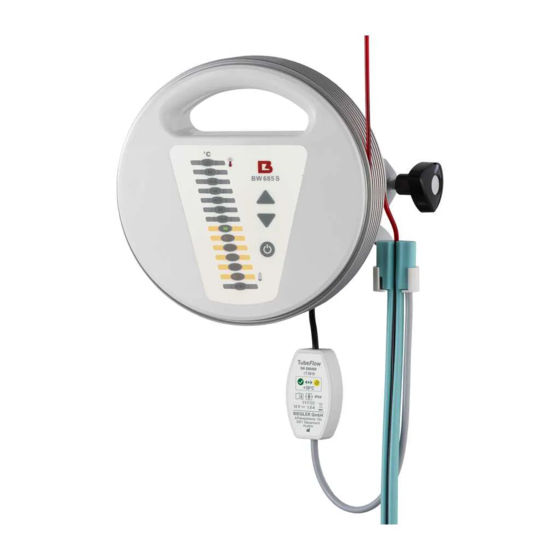
Blood and infusion warmer
Hide thumbs
Also See for BW 685:
- Directions for use manual (28 pages) ,
- Instructions for use manual (25 pages)

Related Manuals for Biegler BW 685


Summary of Contents for Biegler BW 685
- Page 1 Service Instructions Blood and Infusion Warmer BW 685 / BW 685 S Print version BW 685 V 7 Software V 1.5 BW 685 Service Instructions July 2007...
-
Page 2: Table Of Contents
2. Symbols Used ....................4 3. Safety Instructions .................... 5 4. Warranty......................7 5. Safety Shutdown ....................8 6. Setting the temperature .................. 10 7. Service Interface..................... 11 8. Maintenance / Testing Instructions ..............14 _______________________________________________________________________________________ Page 2 BW 685 Service Instructions July 2007... -
Page 3: Technical Data
1. Technical Data ____________________________________________________________________________________ Technical data for BW 685 / BW 685 S: Device: Blood and Infusion Warmer Type designation: BW 685 / BW 685 S Voltage: 230 V / 50 Hz Power consumption: 1.5 A Protection class: Degree of protection:... -
Page 4: Symbols Used
Degree of protection B Control for switching On / Standby - for optional tube warmer Tubeflow Operation Malfunction Do not cover Do not wrap up Do not expose to direct sunlight Do not cut _______________________________________________________________________________________ Page 4 BW 685 Service Instructions July 2007... -
Page 5: Safety Instructions
The device may only be fastened to infusion stands, tripods or equipment rails which are suitable due to their stability and load capacity. • Only sterile consumables prescribed by BIEGLER may be used in conjunction with the BW 685 / BW 685 S. •... - Page 6 Supplementary safety instructions for the accessory tube warmer Biegler Tubeflow BW 685 S: • The Biegler Tubeflow may only be clamped to the Biegler blood warmer BW 685 S with the fixing clamp according to the diagram in the chapter of the instructions for use "Initial operation".
-
Page 7: Warranty
4. Warranty _________________________________________________________________________________________________ Biegler Medizinelektronik provides a warranty for this device for a period of two years from the purchase date. This warranty applies for defects in materials and workmanship and includes both replacement parts and labour. -
Page 8: Safety Shutdown
• This type of shutdown may also activate if the device is stored in the vicinity of strong heat sources or exposed to direct sunlight. _______________________________________________________________________________________ Page 8 BW 685 Service Instructions July 2007... - Page 9 STANDBY display and an intermittent beep. This alarm resets automatically (if the temperature rises again to 37 °C, the alarm stops). If a type of shutdown is activated, the device must be tested immediately and repaired, if necessary. ______________________________________________________________________________________ Page 9 BW 685 Service Instructions July 2007...
-
Page 10: Setting The Temperature
_________________________________________________________________________________________________ • Start the terminal software • Connect the BW 685 with the computer or terminal (RS 232) using the connecting power cable LZ 10B0685 (Biegler ID) • The monitor must now display data output as described in section 7, Service Interface •... -
Page 11: Service Interface
The BW 685 is equipped with a service interface. This serial interface provides different measured values that can be very useful during calibration and trouble- shooting. The BW 685 can be connected directly to a PC or terminal with an appropriate connecting power cable. The data can be displayed using an available terminal programme (hyperterminal). - Page 12 I>S diff meas/setting temp debugging heat output debugging temp. slew rate debugging error counter debugging low temp. Inhibit alarm timer debugging kor_v correction value front service kor_h correction value rear service _______________________________________________________________________________________ Page 12 BW 685 Service Instructions July 2007...
- Page 13 Heater on (used with P%) “Betrieb” Message: BW685 is in operation mode “Standby” Message: BW685 is in standby mode Message: Heater starts with 10% power (for debugging) “Heizung start mit 010” ______________________________________________________________________________________ Page 13 BW 685 Service Instructions July 2007...
-
Page 14: Maintenance / Testing Instructions
CHECKING THE WARM-UP PERIOD This is the time taken by the BW 685 / BW 685 S to heat up to 38.5°C from room temperature. The device is malfunctioning if it takes much longer than one minute. - Page 15 Measuring device used: TESTO Contact Thermometer 935 Precision: ± 1 digit Type K ±0.7 °C ±0.5 % from the measured value ______________________________________________________________________________________ Page 15 BW 685 Service Instructions July 2007...
- Page 16 (Target: < 0.3 Ohm) and leakage current (Target: < 0.75 mA). There is a malfunction if there is a measured value outside the tolerances. These tests must be conducted at the operating temperature. _______________________________________________________________________________________ Page 16 BW 685 Service Instructions July 2007...
- Page 17 The fuse inserts must be especially tested during maintenance work. For this device, either of the following may be used. BW685 230V 1.6 AT primary: BW 685: 500 m AT secondary all ______________________________________________________________________________________ Page 17 BW 685 Service Instructions July 2007...
- Page 18 6.3 Replacement device leakage first measured value current 7. Fuse insert Only after repair carried out. 8. Mechanical condition 9. Dirt 10. Verification of labels Signature of the inspecting personnel: _______________________________________________________________________________________ Page 18 BW 685 Service Instructions July 2007...
- Page 19 The proper conducting of the tasks listed above and the correctness of the information must be confirmed. Comments: Technician Operator __________________ ________________ (Date, Signature) (Date, Signature) ______________________________________________________________________________________ Page 19 BW 685 Service Instructions July 2007...
- Page 20 Mains switch ON Measurement unit: µA Target: 0.00 Threshold: < 500 Interval tol.: 0.00 Rel. tol. 0.00 Measurement unit: µA Target: 0.00 Threshold: < 500 Interval tol.: 0.00 Rel. tol. 0.00 _______________________________________________________________________________________ Page 20 BW 685 Service Instructions July 2007...
- Page 21 The effective value of the network voltage is measured Measurement unit: VOLT Target: 230 Threshold: 0.00 Interval tol.: 0.00 Rel. tol. 0.00 Measurement unit: VOLT Target: 230 Threshold: 0.00 Interval tol.: 0.00 Rel. tol. 0.00 ______________________________________________________________________________________ Page 21 BW 685 Service Instructions July 2007...
- Page 22 REPLACEMENT PARTS LIST BW 685 Biegler ID Description Clamp, complete, BW 685 IA 1000685 Three-cornered grip M5 - complete IB 9000003 Print assembly BW 685 IP 1000685 Ring, complete, BW 685 IR 1000685 Fuse T 500 mA CE 1200500 Fuse T 1.6 A...
- Page 23 GA6004546 GZ5200201 Disconnect device from mains before opening! Fig. 2 – Opening of the BW 685 / BW 685 S ______________________________________________________________________________________ Page 23 BW 685 Service Instructions July 2007...
- Page 24 IR1000685 IP000685 Fig. 3 – Disassembly of the BW ring Pressing fixture (Silicone tube) Fig. 4 – Bimetal safety temperature limiter 45 ± 3˚C Self-resetting (at room temperature) _______________________________________________________________________________________ Page 24 BW 685 Service Instructions July 2007...
- Page 25 LZ10B0685 IA1000685 CJ8256700 Fig. 5 – Connection of the service interface with cable LZ10B0685 CJ4014006 BN1012004 CC1000003 CJ5592072 KN1003001 BN1012004 IB9000003 ______________________________________________________________________________________ Page 25 BW 685 Service Instructions July 2007...
- Page 26 Fig. 6 – BW 685 S Fuse sec. Fuse prim. Fig. 7 – Assembly diagram for conductor board _______________________________________________________________________________________ Page 26 BW 685 Service Instructions July 2007...
- Page 27 MANUFACTURER'S DECLARATION The blood and infusion warmer BW 685 / BW 685 S is a medical product as defined by Directive 93/42/EEC. This is documented by attaching the CE mark. Notified Body: TÜV Product-Service, Approval Number CE0123 MANUFACTURER Biegler GmbH...
Need help?
Do you have a question about the BW 685 and is the answer not in the manual?
Questions and answers