Advertisement
Quick Links
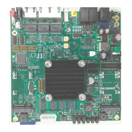
Freescale Semiconductor
P1010RDB-PB Quick Start Guide
P1010RDB-PB Quick Start Guide
1
Introduction to P1010RDB-PB
This quick start guide applies to boards with assembly
revision 700-27904 Rev X4. See the top side of the board to
get the revision number.
This document describes P1010RDB-PB and its related
hardware kit. It also explains and verifies the basic board
operations in a step-by-step format.
This document shows settings for switches, connectors,
jumpers, push buttons, and LEDs, and you can find
instructions for connecting peripheral devices.
© 2013 Freescale Semiconductor, Inc. All rights reserved.
Document Number: P1010RDBPBQS
Contents
1. Introduction to P1010RDB-PB . . . . . . . . . . . . . . . . . . 1
2. Getting Started . . . . . . . . . . . . . . . . . . . . . . . . . . . . . . 2
Rev. 0, 10/2013
Advertisement

Related Manuals for NXP Semiconductors P1010RDB-PB


Summary of Contents for NXP Semiconductors P1010RDB-PB
- Page 1 Contents 1. Introduction to P1010RDB-PB ....1 2. Getting Started ......2 This quick start guide applies to boards with assembly revision 700-27904 Rev X4.
-
Page 2: Getting Started
Section 2.2, “Default Booting Method and Switch Settings • Section 2.3, “Booting the Board Preloaded Binaries on the Board The P1010RDB-PB kit contains: • On-board NAND Flash loaded with early release image files: P1010RDB-PB Quick Start Guide, Rev. 0 Freescale Semiconductor... - Page 3 Follow the given steps to boot a target board: 1. Set the switch settings for SW1, SW2, SW3, SW4 and SW5 as illustrated here. For more details on decoding the switch settings, refer to the P1010RDB-PB Hardware User Guide. Figure 2. Switch Settings 2.
- Page 4 Figure 4. Plug-in Power Adapter 4. Plug the USB miniB to typeA cable in the UART0 receptacle as console port. Attach the serial cable between the P1010RDB-PB UART0 port and a host PC. Figure 5. Attaching to a UART Port 5.
- Page 5 Figure 6. USB to UART Device Driver 6. Configure the serial port of the host PC with the following settings: Figure 7. Configuring Serial Port 7. Push up the power switch to “ON” at the back of unit. P1010RDB-PB Quick Start Guide, Rev. 0 Freescale Semiconductor...
- Page 6 CPU0:1000 MHz, CCB:400 MHz, DDR:400 MHz (800 MT/s data rate) (Asynchronous), IFC:100 D-cache 32 kB enabled I-cache 32 kB enabled Board: P1010RDB-PB, CPLD Ver: v1.0, ROM Loc: NAND I2C: ready SPI: ready DRAM: Detected UDIMM 1 GiB (DDR3, 32-bit, CL=6, ECC off)
- Page 7 PCIe2: Bus 01 - 01 serial Out: serial Err: serial PCB Ver: 1.0 Net: eTSEC1 [PRIME], eTSEC2, eTSEC3 Hit any key to stop autoboot: 9. Power off the unit by pressing down the power switch button. P1010RDB-PB Quick Start Guide, Rev. 0 Freescale Semiconductor...
- Page 8 How to Reach Us: Information in this document is provided solely to enable system and software implementers to use Freescale products. There are no express or implied copyright Home Page: freescale.com licenses granted hereunder to design or fabricate any integrated circuits based on the information in this document.
- Page 9 Mouser Electronics Authorized Distributor Click to View Pricing, Inventory, Delivery & Lifecycle Information: P1010RDB-PB...
Need help?
Do you have a question about the P1010RDB-PB and is the answer not in the manual?
Questions and answers