Table of Contents
Advertisement
Quick Links
®
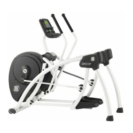
Cybex Arc Trainer
362A
Owner's Manual
Model Number: 362A
USER WEIGHT LIMITATION: 300lbs (136 kg)
SERIAL NUMBER (found on frame):
®
Cybex
and the Cybex logo are registered trademarks of Cybex International, Inc.
®
Arc Trainer
and it's mark are registered trademarks of Cybex International, Inc.
®
Polar
is a registered trademark of Polar Electro Inc.
DISCLAIMER: Cybex International, Inc. makes no representations or warranties regarding the contents of this manual. We reserve the right
to revise this document at any time or to make changes to the product described within it without notice or obligation to notify any person of
such revisions or changes.
© 2011, Cybex International, Inc. All rights reserved.
10 Trotter Drive Medway, MA 02053 • 888-462-9239 • 508-533-4300 • FAX 508-533-5183
www.cybexintl.com • techhelp@cybexintl.com • LT-23110-4 B
P/N LT-23110-4 B
ST-MNL-CB362A-CB-US-01
Advertisement
Table of Contents

Related Manuals for CYBEX Arc Trainer 362A


Summary of Contents for CYBEX Arc Trainer 362A
- Page 1 Polar Electro Inc. DISCLAIMER: Cybex International, Inc. makes no representations or warranties regarding the contents of this manual. We reserve the right to revise this document at any time or to make changes to the product described within it without notice or obligation to notify any person of such revisions or changes.
-
Page 3: Safety Precautions
SAFETY PRECAUTIONS For future service or related questions: Please staple your receipt and/or write in the name and phone number of the retail store where you purchased your Home Arc Trainer. Name: ______________________________ Phone Number: ___________________ Receipt: ______________________ Precautions: WARNING: Failure to Read and Follow the following Precautions could result in Serious Injury! To reduce the risk of burns, fire, electric shock, or injury to persons, read the following important precautions and information before operating the Home Arc Trainer. -
Page 4: Warning Decals
Note: to replace any worn or damaged decals do one of the following : visit www.cybexintl.com to shop for parts online, fax your order to 508-533-5183 or contact Cybex Customer Service at 888-462-9239. if you live outside of the USA, call 508-533-4300. - Page 5 Warning Decals Warning decal part number FS-DC-D350-07...
- Page 6 Warning Decals...
-
Page 7: Caution Decals
Caution Decals Caution decals indicate a potentially hazardous situation, which, if not avoided, may result in minor or Moderate injury. The caution decals are shown below. -
Page 8: Power Requirements
POWER REQUIREMENTS Power Requirements: IMPROPER CONNECTION OF THE EQUIPMENT GROUNDING CONNECTOR CAN RESULT IN A RISK OF AN ELECTRIC SHOCK. CHECK WITH A QUALIFIED ELECTRICIAN OR SERVICE PROVIDER IF YOU ARE IN DOUBT AS TO WHETHER THE UNIT IS PROPERLY GROUNDED. DO NOT MODIFY THE PLUG PROVIDED WITH THE PRODUCT. IF THE PLUG WILL NOT FIT THE OUTLET;... -
Page 9: Pre-Assembly
As you open each box, take inventory of all items contained inside the box. Use the “Content Checklist” and “Hardware Comparison Chart” located on the following pages to assist you in taking inventory of each box. If you are missing any parts or have any assembly questions call your local Cybex Retailer or Cybex Customer Service 1-888-462-9239. Gather your tools: Before starting the assembly, gather all the necessary tools you need to assemble the unit properly. -
Page 10: Contents Checklist
CONTENTS CHECKLIST Carton contents: For your convenience, we have identified the contents of the shipping carton. Please check to make sure you have all of the components before assembly. This chart is provided to help you identify the components used in the assembly of this product. Description Qty. - Page 11 HARDWARE COMPARISON CHART Hardware chart: For your convenience, we have identified the hardware used in the assembly of this product. This chart is provided to help you identify those items that may be unfamiliar to you. Description Qty. Flat hex head bolt M8x16 Button head cap screw M6x16 M8X25 Bolt M10x70 Bolt...
- Page 12 ASSEMBLY STEP 1: Open box, remove the three (3) accessories boxes positioned between the foot pedals and set aside. Remove arms and set aside. Remove the zip tie which tightens the frame on the wooden rack and remove the wooden rack. Determine location of use for the 362A Home Arc Trainer and lift main frame (101) out.
- Page 13 ASSEMBLY STEP 2: With back end elevated, insert Left Rear Support Leg (A06) and Right Rear Support Leg (A06) into the frame and secure with M8x25 Allen Head Cap Bolt (517), Spring washer (516) and Washer (515) on each side as shown.
- Page 14 ASSEMBLY STEP 3: Attach the Left Pedal Swing Arm (106) and Right Pedal Swing Arm (105) with the pivoting bracket on the main frame as shown and secure with M12x70 shoulder bolt (504), 18x12xT3.5 washer (511), 18x12xT3 washer (512) and M12 Nylon Nut (508) on each side.
- Page 15 ASSEMBLY STEP 4: Place the Pedal soft cushion (363) on the Pedal (358,359 ) and place the Pedal on the Pedal Arm and secure the Pedal with 4-M6x12 Screws ( 506 ) from the bottom of pedal as shown .
- Page 16 ASSEMBLY STEP 5: Place spacers on the right and left side of the handlebar shaft (321). Line up the Left Handlebar (A02) lower pivot housing with the shaft on the main frame and the shaft on the Left Handlebar with the Linkage (113), then push both pivot joints in at the same time.
- Page 17 ASSEMBLY STEP 6 Rotate the Left Crank to the lowest position as shown below. Important Note: Failure to rotate the crank arm to the proper position will not allow the unit to be assembled properly. Place the Crank Bushing (505) on the Left Crank Shaft (434) and then mount the Left Crank-Pedal Link Bar (109) on the left crank shaft, attach the washer (510) and Cap (360) on and secure with M8x16 Flat Allen head bolt (501) as shown.
- Page 18 ASSEMBLY STEP 7: With a person holding the console, connect the 12 Pin Upper Cable (610) with the 12 Pin Lower Cable (611). Connect the 4 Pin Upper Hand Pulse Cable (615) and 4 Pin Lower Hand Pulse Cable (616), Insert the extra length of cables into the Console Assembly and insert the 12 pin connector into the hole on Front Tower then place the Console Assembly onto the Front Tower as shown.
- Page 19 ASSEMBLY STEP 8: Insert 3 pieces Nylon Pin (230) into the Left/Outer Frame Join Cover (356 ), mount the Left/Outer and Left/Inner Frame Join Cover (355 ) to cover the left hand side frame joint and secure them with 4 -4x15 taper screws (514) and 2 -4x19 Flat Head Philip screws (507).
- Page 20 ASSEMBLY STEP 9: Lift the front end and attach the Level Adjustment (513) underneath the front stabilizer tube. Level the Home Arc Trainer so it does not move or rock. All assembly steps are now completed. Plug unit into a dedicated wall outlet. NOTE: The Home Arc Trainer should be plugged into a dedicated line or circuit.
-
Page 21: Computer Operation
COMPUTER OPERATION... - Page 22 COMPUTER OPERATION SCAN CHOOSE PROGRAM Buttons INCLINE UP PAUSE/END INCLINE DOWN DISTANCE CALORIES CAL/hr METs DISTANCE CLIMBED STRIDES/min HEART RATE ENTER TIME ADJUSTMENT BUTTON-UP LEVEL ADJUSTMENT BUTTON-DOWN WEIGHT RESISTANCE UP QUICK START RESISTANCE DOWN...
- Page 23 COMPUTER OPERATION Buttons: Program Buttons: Manual: Program button. Press to select P1 manual adjustment program. Biggest Loser: Program button. Press to select P2 Biggest Loser program. Random: Program button. Press to select P3 Random workout program. Fitness: Program button. Press to select 3 Fitness programs : P4 –...
- Page 24 COMPUTER OPERATION Heart Rate: Press to deactivate other data display functions and show the workout heart rate on the center LED display window during the workout. Function activates when Heart Rate LED lights on. Enter: Press to confirm the input workout Time, Level and user Weight during workout program set up procedure.
- Page 25 Dormant State: Connect the power cord, turn on the power switch located at front end, LED dot matrix display shows Cybex logo for 3 seconds and then enters the Dormant State. Before stepping on the pedal or pressing any program buttons including the Quick Start button, the unit will stay in the Dormant State.
- Page 26 COMPUTER OPERATION Biggest Loser: While on the Dormant State, press the Biggest Loser button. The center LED window shows “P2”. Press the Enter button and the center LED window then shows “0” while the LED dot matrix window shows “CAL”. Press the Up or Down Arrow buttons to set up the target calories from 20 up to 9999.
- Page 27 COMPUTER OPERATION P-4 Weight Loss The Weight Loss program is designed for low to medium intensity training that the user can sustain for an extended period of time. It builds from a low intensity baseline to include segments of higher incline and resistance as well as segments that use higher resistance at the base incline.
- Page 28 COMPUTER OPERATION P-5 Cardio The Cardio program is designed for experienced users that desire a high intensity cardiovascular training experience. The 2-minute work interval with high resistance ensures that the aerobic energy system is completely taxed, while the subsequent 2-minute recovery interval enables a repeat at the higher work rate.
- Page 29 COMPUTER OPERATION P-6 Endurance The Endurance program challenges the cardiovascular system in a manner that adjusts the overall intensity to accommodate for fatigue but maintains a similar perceived exertion throughout the workout. The core program is 16 minutes in length. After warm-up the intensity is increased over the next four minutes.
- Page 30 COMPUTER OPERATION P-7 Hills The Hills program uses a 3 ½ minute core in which the incline and resistance both increase over the first 2 ½ minutes, followed by a one-minute reduction in incline and resistance. The reduced workload simulates reaching the top of the hill. The climb is then repeated.
- Page 31 COMPUTER OPERATION P-8 Valleys The Valleys program provides a contrasting mix of incline and resistance. The program uses a five minute core during which the resistance is increased and the incline is reduced over the first three minutes, followed by a reduction in resistance and an increased incline until the valley repeats itself.
- Page 32 COMPUTER OPERATION P-9 Ramps The Ramps program is similar to the Hills program but uses a more linear ramp of both incline and resistance from segment to segment. Ramps is comprised of a 3 ½ minute core during which the incline and resistance both increase over the first 2 ½ minutes, followed by a one-minute reduction of both incline and resistance.
- Page 33 COMPUTER OPERATION Interval Programs: While on the Dormant State, press Interval button. The center LED window shows “P10”. Press the Enter button to select P10 and start the user weight set up. Or press the Up or Down Arrow buttons to select among P10 to P12. Then press the Enter button to start the user weight set up (If Enter button is not pressed within 10 seconds, this procedure will be skipped to the next step, user weight set up) and the center LED window then shows the default user weight “150”...
- Page 34 COMPUTER OPERATION P-11 Interval 2 This program is designed for those who desire a higher intensity interval training program. It uses a fixed incline with variable resistance applied in a repeating 1:1 work to rest ratio. Each work and rest segment lasts 60 seconds. The resistance of the rest segments is approximately 55 to 65% of the work segments.
- Page 35 COMPUTER OPERATION P-12 Hill Interval The Hills program is designed to give the user the experience of hiking in hilly terrain. This program uses intervals of moderate resistance and incline to simulate relatively flat areas and intervals of substantially greater incline and resistance to simulate steeper grades.
-
Page 36: Important Steps
IMPORTANT STEPS Warning: Before using this product, please consult your personal physician for a complete physical examination. Frequent and strenuous exercise should be approved by your doctor first. If any discomfort should result from your use of this product, stop exercising and consult your doctor. -
Page 37: Target Heart Rate
TARGET HEART RATE Finding your pulse: To make sure your heart is beating in its target zone, you’ll need to know how to monitor your heart rate. The easiest way is to feel the pulse in the carotid artery on the left side of your neck, in the notch between the windpipe and the large neck muscles. When you detect your pulse, use as little pressure as possible while you are counting beats. -
Page 38: Muscle Chart
MUSCLE CHART Targeted muscle groups: The exercise routine that is performed on this product will develop primarily lower body muscle groups. These muscle groups are shown in gray color on the chart below. MUSCLE GROUPS Deltoid muscles Gastrocnemius muscles Pectoral muscles Trapezius muscles Bicep muscle Tricep muscles... -
Page 39: Stretching Routine
STRETCHING ROUTINE Warm up and cool down: A successful exercise program consists of a warm-up, aerobic exercise, and a cool-down. Do the entire program at least two and preferably three times a week, resting for a day between workouts. After several months, you can increase your workouts to four or five times per week. -
Page 40: Troubleshooting
TROUBLESHOOTING Troubleshooting NOTE: Do not touch any internal electric wires. Contact Cybex Customer Service for a list of certified Cybex Service Technicians in your area. Home Arc Trainer will not start: 1. Make sure the power cord is plugged into a surge protector, the surge protector is plugged into a properly grounded outlet and the surge protector is turned on (refer to the Power Requirements section in this manual).
Need help?
Do you have a question about the Arc Trainer 362A and is the answer not in the manual?
Questions and answers