Sign In
Upload
Download
Table of Contents
Contents
Add to my manuals
Delete from my manuals
Share
URL of this page:
HTML Link:
Bookmark this page
Add
Manual will be automatically added to "My Manuals"
Print this page
×
Bookmark added
×
Added to my manuals
Manuals
Brands
OTC Manuals
Welding System
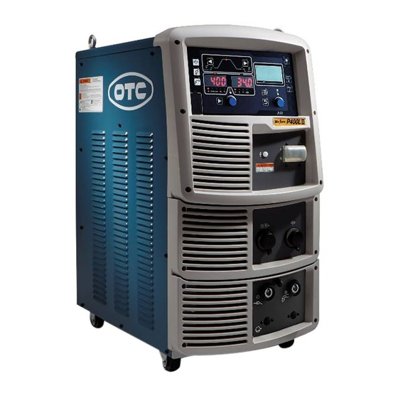
Welbee P400L II
Owner's manual
OTC Welbee P400L II Owner's Manual
Hide thumbs
1
2
3
Table Of Contents
4
5
6
7
8
9
10
11
12
13
14
15
16
17
18
19
20
21
22
23
24
25
26
27
28
29
30
31
32
33
34
35
36
37
38
39
40
41
42
43
44
45
46
47
48
49
50
51
52
53
54
55
56
57
58
59
60
61
62
63
64
65
66
67
68
69
70
71
72
73
74
75
76
77
78
79
80
81
82
83
84
85
86
87
88
89
90
91
92
93
94
95
96
97
98
99
100
101
102
103
104
105
106
107
108
109
110
111
112
113
114
115
116
117
118
119
120
121
122
123
124
125
126
127
128
129
130
131
132
133
134
135
136
137
138
139
140
141
142
143
144
145
146
147
148
149
150
151
152
153
154
155
156
157
158
159
160
161
162
163
164
165
166
167
168
page
of
168
Go
/
168
Contents
Table of Contents
Troubleshooting
Bookmarks
Table of Contents
Forward
Service and Support
Important Information
Use of the Product
Safe Use of the Product
Copyright
When Exporting the Product
Disposal of the Product
Table of Contents
Chapter 1 Safety Information
Warning Symbols
Safety Precaution
Operating Precautions
Precautions for Power Supply and Electric Shock
Precautions for Handling of Plastic Parts
Precautions for Disassembling and Modifying the Welding Power Source
Precautions for Air Discharge and Use of Respiratory Protective Equipment
Precaution for Protective Equipment
Precautions for Flammable Materials
Precautions for Gas Cylinder and Gas Regulator
Precautions for Rotating Part
Principal Safety Standards
Chapter 2 Product Specification and Configuration
Specification
Specifications
Applicable Welding Method
External Dimensions
Rated Duty Cycle
Product Configuration
Standard Composition
Accessory (Supplied)
Accessory (Not Supplied)
Optional Accessories
Part Names
Front Panel
Rear Panel
Chapter 3 Transportation and Installation
Required Equipment
Welding Power Source Equipment
Ventilation Equipment/Partial Exhaust Facility
Installation Environment
Electromagnetic Interference
Transportation Procedure
Transportation with Lifting Lug
Manual Transportation with Carts
Chapter 4 Connection
Precautions for Connection Procedure
And Grounding
Connecting the Welding Power Source
Connection of Cable at Output Side
Connection of Wire Feeder
Connection of Welding Torch
Connection of Voltage Detection Cable (Voltage Detection Cable Is Used)
Connection at TIG Welding
Connection at DC STICK Welding
Connection of Shield Gas
Connection of Cooling Water Circulation Device and Water Hose (in Using Water-Cooled Welding Torch)
Grounding and Connection of Input
Power Supply
Confirmation of Connection
Connection of External Equipment
Connection of Robot
Connection of Automatic Machine
Wiring of Voltage Detection Cable at Base
Metal Side
Wiring to Wire Feeder
Wiring to Welding Power Source
Wiring Example of Voltage Detection Cable
Chapter 5 Welding Operation
Precaution at Welding Operation
Precautions for Air Discharge and Use of Respiratory Protective Equipment
Precaution for Protective Equipment
Precautions on Welding Place
Check before Welding
Power on and Gas Supply
Wire Inching
Check and Setting of Welding Condition
Reading Welding Condition
Preventing Erroneous Operation on Operation Panel
Performing Welding Operation
Operation of Welding Start
Operation During Welding
Operation at Welding End
Chapter 6 Welding Condition
List of Welding Conditions
Parameter (Welding Parameter)
Function
Internal Function
Function on Operation Panel
Operation Panel
Setting Screen
Welding Conditions
Basic Welding Conditions
Useful Functions
Preparing Welding Conditions
Memory Function of Welding Conditions
Memory Registration of Welding Conditions
Read out of Welding Conditions
Deletion of Memory Registration
Setting Welding Conditions
Welding Mode Setting
Setting Welding Conditions
Setting Welding Parameter
Crater Setting
Arc Spot Time
Welding Voltage Adjustment
Arc Characteristics Adjustment
Penetration Control Adjustment
Adjustment of Wave Frequency
Welding Guide
Setting Internal Functions
Setting Procedure
Detailed Information on Internal Functions
Operation of Analog Remote Control
(Optional)
Chapter 7 Administrator Functions
Protection of Welding Conditions
Setting/Changing Password
Disabling Erroneous Operation Prevention
Welding Result Control Function
Setting Welding Result Control Function
Details of Welding Control Items
Data Backup (Utilization of Data)
Setting of Welding Conditions/Internal Functions
Simplified Data Log Function
Failure Log Function
Welding Result Control Function
Backup Operation
Importing Backup Data
Initializing Welding Conditions and Internal Functions
Checking the Software Version and Serial Number
Calibration Mode
Adjustment of Output Current
Adjustment of Output Voltage
System Setting
Chapter 8 Maintenance and Inspection
Precautions for Maintenance and Inspection
Daily Inspection
Periodical Inspection
Periodical Replacement Parts
Insulation Resistance Measurement and Withstand Voltage Test
Chapter 9 Troubleshooting
Action in Case of Error
Troubleshooting
Chapter 10Reference Materials
10.1 Parts List
Configuration
Spare Parts List
Reference Drawing
10.2.1 Schematic Diagram
Parts Layout Drawing
Guide for Changing Welding Conditions
Samples of Welding Condition Settings
Advertisement
Quick Links
1
Chapter 9 Troubleshooting
Download this manual
OWNER'S MANUAL
Welbee P400L II
P500L II
July, 2021
DAIHEN Corporation
Manual No. : P30345-1
Table of
Contents
Previous
Page
Next
Page
1
2
3
4
5
Advertisement
Table of Contents
Troubleshooting
CHAPTER 9 TROUBLESHOOTING
145
Troubleshooting
149
Need help?
Do you have a question about the Welbee P400L II and is the answer not in the manual?
Ask a question
Questions and answers
Related Manuals for OTC Welbee P400L II
Welding System OTC Welbee P500L II Owner's Manual
(168 pages)
Welding System OTC Welbee P400 II Owner's Manual
(155 pages)
Welding System OTC Welbee M350 II Owner's Manual
(148 pages)
Welding System OTC Welbee M350L II Owner's Manual
(150 pages)
Welding System OTC DP-400 Owner's Manual
Digital inverter (81 pages)
Welding System OTC DTX-2200 AC/DC User Manual
(80 pages)
Welding System OTC CPTX 270 Manual
(54 pages)
Welding System OTC HR 22 User Manual
(20 pages)
Welding System OTC MTX-3531 Instruction Manual
Welding torch for robot coaxial power cable for robot (20 pages)
Welding System OTC CPTX 450-2w Synergy User Manual
(88 pages)
Welding System OTC Synergy CPTX 400 Operating Instructions Manual
(82 pages)
This manual is also suitable for:
Welbee p500l ii
Table of Contents
Print
Rename the bookmark
Delete bookmark?
Delete from my manuals?
Login
Sign In
OR
Sign in with Facebook
Sign in with Google
Upload manual
Upload from disk
Upload from URL


Need help?
Do you have a question about the Welbee P400L II and is the answer not in the manual?
Questions and answers