Table of Contents
Advertisement
Quick Links
Advertisement
Table of Contents

Related Manuals for OTC DTX-2200 AC/DC


Summary of Contents for OTC DTX-2200 AC/DC
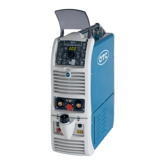
- Page 1 User Manual DTX-2200 AC/DC DTX-3000 AC/DC...
-
Page 2: Table Of Contents
Contents 1 Contents Contents ................................2 Foreword ................................4 Regulations for the prevention of accidents ...................... 6 Connection of the power source ......................6 Operator protection ..........................7 Prevention of fire and slag ........................7 ... - Page 3 Contents 15.3 AIR AND/OR WATER-COOLED TORCH UP/DOWN ................62 15.4 Interfacing accessories (optional) ......................63 Maintenance ............................. 64 16.1 Daily ..............................64 16.2 Weekly ..............................64 16.3 All six months ............................64 ...
-
Page 4: Foreword
Foreword 2 Foreword Thank you for choosing our product. Your new welding equipment from OTC DAIHEN EUROPE GmbH offers you the highest quality and latest technology. To exploit the full capabilities of this device and to enjoy it for many years, please read these instructions carefully before connecting and commissioning the device. - Page 5 Foreword Electric and Magnetic Fields During the operations of the welding machine an electromagnetic field (EMF) can be created and may caused health problems. The operator is responsible for the proper installation and use of the device according to the manufacturer’s instructions.
-
Page 6: Regulations For The Prevention Of Accidents
Regulations for the prevention of accidents 3 Regulations for the prevention of accidents The use of welding equipment and welding itself are always associated with a certain safety risk. Therefore each set up and operation of the device assumes that the instruction manual is understood and complied. The properly used welding machine grants a high degree of operational security but can, in case of improper handling, lead to property and personal damage. -
Page 7: Operator Protection
Regulations for the prevention of accidents Operator protection All people must be protected during the welding process, with appropriate measures against UV radiation, noise, heat and gas pollutants emitted during welding. Never expose yourself to the influences of arc and the hot metal slag without a protective mask and appropriate protection. Welding work without consideration of these standards could cause serious health problems. -
Page 8: Risk Of Poisoning
Regulations for the prevention of accidents Risk of poisoning Gases and fumes that are harmful when inhaled for a longer time can be released while welding. Because of this, the following safety guidelines have to be observed: Ensure that you have adequate ventilation for the work area. During the processing of materials such as, beryllium, potassium, zinc, or galvanized and painted ... -
Page 9: Transport Of The Power Source
Regulations for the prevention of accidents Transport of the power source The unit is generally suitable for transport. The following requirements must be made to ensure an ease transport: The device may only be lifted and transported with the provided handle. ... - Page 10 Regulations for the prevention of accidents Dust and cooling system: The device has to be positioned in a way that sufficient air can flow through the cooling fins and the cooling channels. The unit adjusts the cooling system automatically! Please pay attention, that no metal dust can be sucked.
-
Page 11: Description
TIG welding for all metals, aluminium, and its alloys, as well as MMA welding with any type of electrode. The DTX-2200 AC/DC units are the ideal solution for all professional welding applications and for maintenance work that calls for power and portability. - Page 12 - Anti-sticking function to avoid the electrodes sticking. • DTX-2200 AC/DC - The PFC device makes the wave form of the current absorbed sinusoidal, which results in no harmonic disturbance on the mains and optimization of absorption, which allows you to use the generator’s full power with a 16 A fuse, as well as ensuring greater protection of the welding machine against fluctuations in the power supply voltage.
-
Page 13: Technical Data
Technical Data 6 Technical Data The general technical data of the system are summarized in Table1. Table1 DTX-2000 AC/DC DTX-3000 AC/DC Model Power supply 50/60 Hz 1~ 230 ±20% 3~ 400 ±20% Power supply: Z Ω 0,092 Input power @ I Delayed fuse (I @ 100%) Power factor / cosφ... -
Page 14: Usage Limits (Iec 60974-1)
The system essentially consists of: • DTX AC/DC weld unit. • Separately: - Welding TIG torches (optional). - Neck strap (optional DTX-2200 AC/DC). - Ground cable, complete with rapid coupling (optional). - Coolant unit for welding torch (optional). - Trolley for transportation (optional). -
Page 15: How To Lift Up The Machine
Installation 10 How to lift up the machine The weld machine has a strong handle all in one with the frame, used for transporting the machine manually only. NOTE: These hoisting and transportation devices conform to European standards. Do not use other hoisting and transportation systems. -
Page 16: Prepare The Machine For Welding
“O”. DTX-2200 AC/DC (Single-phase power supply) Use the welder’s own plug to connect it up to the main power supply. Proceed as follows if you have to replace the plug: •... -
Page 17: Outer View Of The Dtx-202 Tig
Outer view of the DTX-202 TIG 13 Outer view of the DTX-202 TIG Command and Control Units (Image 1) MTH command and control panel. Pos. 1 Positive pole quick connection. Pos. 2 Fast coupling TIG torch gas tube. Pos. 3 TIG weld auxiliary control connector (torch Pos. -
Page 18: Operation
Operation 14 Operation 14.1 TIG-welding In the TIG process welding is achieved by melting the two metal pieces to be joined, with the possible addition of material from the outside, using an arc ignited by a tungsten electrode. The molten bath and the electrode are protected by and inert gas (e.g. - Page 19 Operation Image 3 Image 4 TIG WELDING WITH “Lift” TYPE STRIKING 4a) Open the gas cylinder and flow regulator (8-14 l/min). 5a) Put the electrode at the point at which welding is to begin, put the TIG torch at an angle so that the edge of the gas nozzle is not on top of the piece to be welded, keeping contact between the point of the electrode and the piece to be welded (Image.
-
Page 20: Part To Be Welded
Operation 14.1.1 Part to be welded The part to be welded must always be connected to ground in order to reduce electromagnetic emission. Much attention must be afforded so that the ground connection of the part to be welded does not increase the risk of accident to the user or the risk of damage to other electric equipment. -
Page 21: Electrode Welding (Mma)
Operation 14.2 Electrode welding (MMA) The welding electrode is used to weld most metals (various types steel, etc.),for which rutilic and basic electrodes are used. 1) Connecting the welding cables (Image 6): Disconnect the machine from the main power supply and connect the welding cables to the output terminals (Positive and Negative) of the welding machine, attaching them to the clamp and ground with the polarity specified for the type of electrode being used (Image 6). -
Page 22: Welding Parameters
Operation 14.2.2 Welding Parameters Table 4 shows some general indications for the choice of electrode, based on the thickness of the parts to be welded. The values of current to use are shown in table 5 with the respective electrodes for the welding of common steels and low-grade alloys. -
Page 23: Control Panel Mta22 / Mta30
Operation 14.3 Control panel MTA22 / MTA30 14.3.1 Panel surface Image 7 ■ VRD The Voltage Reduction Device (VRD) is a safety device that reduces the voltage. It prevents voltages forming on the output terminals that may pose a danger to people. Two-tone LED (off - red - green) indicates enabling of the VRD device. - Page 24 Operation ■ ELECTRODE DIAMETER For TIG welding with HF ignition, it allows you to use the relevant key to set the diameter of the tungsten electrode used, and/or to change it using the ENCODER knob, in order to achieve the best control of the AC arc in a synergic manner.
- Page 25 Operation SPOT WELDING This can be used by pushing the torch button to spot weld for a preset period of time (in seconds) at the end of which the arc switches off automatically. The tack welding function is divided into 3 types: •...
- Page 26 Operation ■ WAVE During TIG AC welding with HF ignition, it makes it possible to control the following wave shapes: control the following wave shapes: DYNAMIC TIG SPEED TIG COLD TIG SOFT TIG DYNAMIC TIG Square wave: highly dynamic arc for all applications. WARNING: LED switched on and steady.
- Page 27 Operation ■ PULSE When using one of the 3 TIG welding processes, it makes it possible to set one of the 4 pulsation modes available on the welding machine, using the relevant button: SYN PULSE FAST PULSE ULTRA FAST PULSE SLOW PULSE Synergic pulse (SYN PULSE) WARNING:...
- Page 28 Operation ■ WELDING PARAMETERS Each time the button is pushed, the welding machine selects the next function according to the machine configuration, the welding process, the welding mode, etc.. STANDARD CONFIGURATION Electrode welding (MMA) When using the electrode welding process, this allows you to set up the following welding parameters, based on which LED is flashing: HOT START ARC FORCE...
-
Page 29: Displaying The Software Version Installed
Operation PULSATION FREQUENCY f WARNING: NOT programmable when SLOW pulsation mode is active. SPECIAL CONFIGURATION (only for expert welders) TIG welding For this configuration, in addition to the parameters already defined for the STANDARD configuration, you can also set the following parameters: IGNITION CURRENT WARNING: This can only be programmed when the TIG with HF ignition welding process is used. -
Page 30: Electrode Welding (Mma)
Operation 14.3.3 Electrode welding (MMA) 1) Start the welding machine by turning the power supply switch to position I. 2) WELDING PROCESS SELECTION Push the WELDING PROCESS SELECTION key (T7) to select the ELECTRODE welding processes for welding with “HOT START” or “ARC FORCE” devices that can be programmed by the user. 3) Turn the ENCODER knob (E) until the DISPLAY shows the CURRENT VALUE at which you wish to weld, in relation to the diameter of the electrode you are using. -
Page 31: Tig "Ac" Welding
Operation The value for the welding parameters can be regulated using the ENCODER knob (E). 5) To exit these functions hold the WELDING PARAMETERS SELECTION key (T10) down for about 1 second, after which the DISPLAY INDICATION LED switches on and the welding machine is once again ready to weld at the current indicated on the DISPLAY (D). - Page 32 Operation To confirm the diameter selected, simply push the ELECTRODE DIAMETER Key (T8) again (ELECTRODE DIAMETER LED off). 4) SELECTING THE WAVE SHAPE By pushing the WAVE (T3) button the operator can choose the best wave shape for their welding needs, from the 4 wave shapes included: DYNAMIC TIG SPEED TIG...
- Page 33 Operation 2200 AC/DC 3000 AC/DC TIG AC SPEED TIG 5 - 220 A 5 - 300 A COLD TIG Triangular wave: low heat generation with reduced distortion, ideal for minor thicknesses. WARNING: switched on and flashing. The display shows the “RMS” current value for pre-set- ting and welding. 2200 AC/DC 3000 AC/DC TIG AC...
- Page 34 Operation 5A) BALANCING of the TIME (t) (-35-+10) It allows you to adjust the time (t) the positive or negative electrode stays in place independently, guaranteeing perfect control of penetration and cleanliness, drastically reducing side incisions. Display Display Display Push the BALANCING and FREQUENCY key (T4) once and use the ENCODER Knob (E) to regulate the value indicated on the DISPLAY (D).
- Page 35 Operation 5B) BALANCING the AMPLITUDE of the CURRENT (I) (-50-+20) It is possible to adjust the amplitude of the current (I) while the electrode stays in place independently, using positive or negative values, guaranteeing perfect control of penetration and cleanliness, drastically reducing side incisions. Display 150% Display...
- Page 36 Operation 5C) BALANCING ( BALANCE PLUS) It is possible to adjust the time (t) and amplitude of the current (I) while the electrode stays in place simultaneously and independently, using positive or negative values, guaranteeing perfect control of penetration and cleanliness, drastically reducing side incisions. For simultaneous setting of the parameters, following the instructions given in points 5A and 5B in succession, with the help (if necessary) of the example shown below.
-
Page 37: Tig „Dc" -Welding
Operation 7) Press the WELDING MODE SELECTION Key (T9) and go to one of the 4 options available: Bi-Level SPOT WELD 8) By pushing the WELDING PARAMETERS SELECTION key a number of times it is possible to set the various TIG WELDING PARAMETERS (see the “TIG AC and DC Welding” paragraph - WELDING PARAMETERS). -
Page 38: Tig "Ac And Lift Dc" Welding With The Spot Welding Function On
Operation To confirm the diameter selected, simply push the ELEC- TRODE DIAMETER Key (T8) again (ELECTRODE DIAME- TER LED off). 4) Press the WELDING MODE SELECTION key (T6) and go to one of the 4 options available: Bi-Level SPOT WELDING Turn the ENCODER knob (E) until the DISPLAY (D) shows the CURRENT VALUE at which you wish to weld. -
Page 39: Tig Hf Dc Welding With Tack Function Active And Single Coldtack Point
Operation 2) Press the WELDING PROCESS SELECTION Key (T7) and select one of the welding machine’s 2 TIG processes: TIG “HF AC” TIG “Lift DC” 3) Press the WELDING MODE SELECTION Key (T9) and go to one of the SPOT WELDING function. 4) Press and release the WELDING PARAMETERS SELECTION Key (T10) until the SPOT WELD LED starts flashing. -
Page 40: Tig Hf Dc Welding With Tack Function Active And Multi Coldtack Point
Operation 1) Start the welding machine by turning the power supply switch to position I. 2) Push the SELECT WELDING PROCESS (T5) key and select the TIG DC process, with HF ignition. 3) Press the WELDING MODE SELECTION Key (T9) and go to one of the SPOT WELDING ColdTack function. - Page 41 Operation 1) Start the welding machine by turning the power supply switch to position I. 2) Push the SELECT WELDING PROCESS (T5) key and select the TIG DC process, with HF ignition. 3) Press the WELDING MODE SELECTION Key (T9) and go to one of the SPOT WELDING Multi- coldTack function.
-
Page 42: Tig-Welding - Welding Parameters
Operation 14.3.9 TIG-welding – Welding parameters The DTX HF can be configured in the following 2 ways: • STANDARD (Std) configuration. • SPECIAL (SPE) configuration. 14.3.9.1 STANDARD CONFIGURATION (Std) When it leaves the factory the welding machine is normally configured in STANDARD (Std) mode. To check the configuration, carry out the following operations: 1) When the welding machine is off, push and hold the “PRG”... - Page 43 Operation INITIAL welding CURRENT 2200 AC/DC 3000 AC/DC TIG DC 5 - 220 A 5 - 300 A TIG AC DYNAMIC TIG 5 - 220 A 5 - 300 A SPEED TIG 5 - 220 A 5 - 300 A COLD TIG 16 - 127 A 5 - 173 A...
- Page 44 Operation SLOW PULSE TIG pulse welding with manual setting of parameters. WARNING: This can only be programmed when the 3 TIG welding processes are used. Press the PULSE key (T5) until the requited pulsation is active. Press the WELDING PARAMETERS SELECTION key (T10) a number of times to set the following (in addition to the WELDING PARAMETERS defined as being “BASIC”): PEAK CURRENT I ...
- Page 45 Operation BASE current duration 2200 AC/DC - 3000 AC/DC TIG DC 0,01 - 0,99 sec TIG AC 0,10 - 0,99 sec To exit the setting phase, hold the WELDING PARAMETERS SELECTION key (T10) down for about 1 second. FAST PULSE TIG pulse welding with manual setting of parameters.
- Page 46 Operation PULSATION FREQUENCY f 2200 AC/DC - 3000 AC/DC Fast 0,5 – 500 Hz To exit the setting phase, hold the WELDING PARAMETERS SE- LECTION key (T10) down for about 1 second. ULTRA FAST PULSE TIG pulse welding with manual setting of parameters. WARNING: This can only be programmed when the TIG DC with HF ignition or TIG DC with “Lift”...
- Page 47 Operation BASE CURRENT I 2200 AC/DC 3000 AC/DC 5 - 220 A 5 - 300 A PEAK CURRENT I 2200 AC/DC 3000 AC/DC 5 - 220 A 5 - 300 A PULSATION FREQUENCY f 2200 AC/DC - 3000 AC/DC ULTRA FAST 500 - 2000 Hz To exit the setting phase, hold the WELDING PARAMETERS SE- LECTION key (T10) down for about 1 second.
- Page 48 Operation This function, which is good for less skilled operators, makes it possible to change the pulsation parameter (Peak current I ) and the other values for the corresponding pulsation parameters (Base current I - Pulsation frequency f ) vary automatically. To exit the setting phase, hold the WELDING PARAMETERS SELECTION key (T10) down for about 1 second.
- Page 49 Operation LEVEL PEAK CURRENT I 2200 AC/DC 3000 AC/DC TIG DC 5 - 220 A 5 - 300 A TIG AC DYNAMIC TIG 5 - 220 A 5 - 300 A SPEED TIG 5 - 220 A 5 - 300 A COLD TIG 16 - 127 A 5 - 173 A...
- Page 50 Operation LEVEL PEAK CURRENT I 2200 AC/DC 3000 AC/DC 5 - 220 A 5 - 300 A LEVEL PEAK CURRENT I 2200 AC/DC 3000 AC/DC 5 - 220 A 5 - 300 A LEVEL BASE CURRENT I 2200 AC/DC 3000 AC/DC 5 - 220 A 5 - 300 A PULSATION FREQUENCY f...
- Page 51 Operation LEVEL PEAK CURRENT I 2200 AC/DC 3000 AC/DC 5 - 220 A 5 - 300 A LEVEL PEAK CURRENT I 2200 AC/DC 3000 AC/DC 25 - 220 A 25 - 300 A LEVEL BASE CURRENT I 2200 AC/DC 3000 AC/DC 5 - 220 A 5 - 300 A PULSATION FREQUENCY f...
- Page 52 Operation LEVEL PEAK CURRENT I 2200 AC/DC 3000 AC/DC 25 - 220 A 25 - 300 A WARNING: When the SYN PULSE function is active, the 1 level PEAK CURRENT ( I ) is regulated to achieve a synergy with the values for the other 1 level parameters ( I , f ).
- Page 53 Operation 5) Press the “PRG” PROGRAM key (T2) to confirm. The WELDING PARAMETERS included, that can be programmed and changed (by turning the ENCODER knob) in the SPECIAL (SPE) configuration, along with those in the STANDARD configuration, can be set by pushing the WELDING PARAMETER SELECTION button (T10) successively: IGNITION CURRENT 2200 AC/DC...
-
Page 54: Editing The Maximum And Minimum Limits For Welding Parameters
Operation FINAL welding CURRENT 2200 AC/DC 3000 AC/DC TIG DC 5 - 220 A 5 - 300 A TIG AC 5 - 220 A 5 - 300 A DYNAMIC TIG SPEED TIG 5 - 220 A 5 - 300 A COLD TIG 16 - 127 A 5 - 173 A... -
Page 55: Creating And Memorising Automatic Welding Points
Operation L12 PRE -GAS duration (maximum limit settable from 1, 00 to 2, 50 sec) L13 SLOPE UP duration (maximum limit settable from 5,00 to 10,0 sec) MINIMUM CURRENT for remote controls - minimum limit settable: 2200 AC/DC 3000 AC/DC 5 - 220 A 5 - 300 A WARNING: If the minimum limit setting (for the remote control MINIMUM CURRENT) is greater than or equal to... -
Page 56: Programmed And/Or Manual Welding
Operation 2) To SAVE the PROGRAM hold the “MEM” SAVE Key (T1) down until the DISPLAY reads “Sto”. 3) The WELDING PROGRAM has now been saved and its number appears in the DISPLAY (D) along with the other settings saved (corresponding LEDs on without flashing). 14.3.12 PROGRAMMED and/or MANUAL welding PROGRAMMED WELDING When the WELDING PROGRAM has been saved, the operator can weld using only pre-set values as they cannot... -
Page 57: Calling Up Saved Programs
Operation 5) Rotate the ENCODER Knob (E) to scroll the programs until you find an empty, unused program slot. 14.3.13 Calling up saved programs 1) Hold the SET/PRG key (T2) down (about 3 seconds) until the DISPLAY (D) shows the number of the program selected flashing (e.g. -
Page 58: Viewing The Parameters Set
Operation 14.3.14 Viewing the parameters set 1) Call up the program required (see the “Calling up saved programs” paragraph). 2) Press and release the WELDING PARAMETERS SELECTION key (T10) to view the parameters set in sequence. Hold the WELDING PARAMETERS SELECTION key (T10) down for more than 1 second to go back to the program selected. -
Page 59: Auxiliary Functions
Operation When the control panel switches on the VRD LED will come on and will be GREEN, which means that the VRD function is on. To “deactivate” the VRD device and therefore start to weld, follow this simple procedure: First touch the work piece with the electrode, then detach it and ignite the arc within a MAX of 0,3 seconds, otherwise if this time is exceeded the VRD device starts and prevents welding. -
Page 60: Error And Protection Conditions
Operation 14.3.18 Error and protection conditions The equipment is protected against problems and if any arise the DISPLAY shows fixed or flashing (error code) messages (depending on the type of error) that serve to inform the operator that a fault has occurred in the equipment (see table 5). - Page 61 (thermostat activated). Automatic reset error. WARNING: The DTX-2200 AC/DC welding machine has a built-in electronic protective device to deal with fluctuations in mains voltage that switches the machine off automatically (voltage exceeding 300 V), without indicating any type of error or warning message for the operator. Subsequently it starts functioning again automatically when the voltage has dropped to below the value indicated above.
-
Page 62: Optional
Optional 15 Optional The remote controls can be only used in the 2-STROKE and 4-STROKE welding modes. 15.1 MANUAL REMOTE CONTROL WARNING: When using the machine for TIG welding it is OBLIGATORY to use the kit for simultaneously use. Weld current can be measured at a distance by connecting up this control. The display will show the previous maximum weld current value set on the welder. -
Page 63: Interfacing Accessories (Optional)
Optional If a remote control is connected (followed by the self-recognition procedure), if it has been pre-set for automatic welding. 15.4 Interfacing accessories (optional) “RoboMAT 1” analogue / digital robot interface Fitted on the back of the DTX-3000 AC/DC welding machine (see example, Pos. -
Page 64: Maintenance
Maintenance 16 Maintenance Under normal operating conditions the DTX-2200 AC/DC , DTX-3000 AC/DC require very little maintenance operations. To ensure a longtime durability, you should pay attention to the following aspects: Temporary the device must be blown out with compressed dry air. Make sure not to aim the air jet directly onto the electrical components, in order to avoid damaging them. -
Page 65: Troubleshooting
Troubleshouting 17 TROUBLESHOOTING The supply line is attributed with the cause of the most common difficulties. In the case of breakdown, proceed as follows: 1) Check the value of the supply voltage 2) Check that the power cable is perfectly connected to the plug and the supply switch 3) Check that the power fuses are not burned out or loose 4) Check whether the following are defective: •... -
Page 66: Meaning Of Graphic Symbols On The Machine
Troubleshooting 17.3 MEANING OF GRAPHIC SYMBOLS ON THE MACHINE Power supply switch Connector for the remote control System for use in environments with increased WARNING! risk of electroshock Product suitable for free circulation in the European Fast coupling TIG torch gas tube Community Before using the equipment you should carefully Danger! High voltage... -
Page 67: Wiring Diagram
Wiring diagram 18 WIRING DIAGRAM •1 •2 •3 •4 •5 •6 •7 •8 •9 •10 •11 •12 •13 •14 •15 •16 •17 •18 •19 •20 FCTA L1-2 •21 •22 •23 •24 •25 •26 •27 •28 •29 •30 S-AI S-INT DIG •31 •32 •33... -
Page 68: Colour Key
Wiring diagram (DTX-2200 AC/DC) 18.2 Colour key Orange-Black Orange Sky Blue White Blue White Black Grey Yellow Yellow-Green Brown Black Pink Green Violet DTX-2200-3000 AC/DC... - Page 69 Wiring diagram (DTX-2200AC/DC) DTX-2200-3000 AC/DC...
- Page 70 Wiring diagram (DTX-2200 AC/DC) DTX-2200-3000 AC/DC...
- Page 71 Wiring diagram (DTX-3000 AC/DC) DTX-2200-3000 AC/DC...
- Page 72 Wiring diagram (DTX-3000 AC/DC DTX-2200-3000 AC/DC...
-
Page 73: Spare Parts List
Spare parts list 19 Spare parts list Pos. DTX-2200 Description AC/DC 352453 Front rack transparent visor 447846C DTX-2200 AC/DC Membrane keyboard 438888 Ø29mm Knob without index 468757 Logo sticker Ø20mm 352452A Front panel without logo sticker Ø20mm 403611 Quick connection... - Page 74 Spare parts list Pos. DTX-2200 Description AC/DC 377094 EMC filter PCB 413538 EMC filter PCB wiring 413536 Auxiliary wiring 286036 "Dual Boost Chopper" IGBT 286038 "Full Bridge" IGBT 376930 Torch filter with connector 403782 Terminal for 3x2 poles female connector 419074 3x2 Poles female connector 352466...
- Page 75 Wiring diagram (DTX-3000 AC/DC Pos. DTX-2200 Description AC/DC 431331 Foot 404933 Base 352944 Dinse Insulation 449495 Internal metallic frame 463217 Transformer support 481402 Transformer 240234 Inductor 240232 PFC inductors 239995 HF transformer 427681 HF filter 481946 Current transducer 486383 Fan motor 425933 Gas solenoid valve 286041...
- Page 76 Spare parts list Pos. DTX-3000 AC/DC Description 352453 Front rack transparent visor 447859C Membrane Keyboard DTX-3000 AC/DC 438888 Ø29mm Knob without index 468757 Logo sticker Ø20mm 352452A Front panel without logo sticker Ø20mm 403611 Quick connection 403635 Gas quick connection 468282 Front sticker 419050...
- Page 77 Spare parts list Pos. DTX-3000 AC/DC Description 413466 Auxiliary wiring 413518 RoboMat 1 wiring (only for DTX-3000 AC/DC R) 478867 Primary circuit thermistor 353052 Inverter PCB insulation 239989 HF transformer 376930 Torch filter with connector 427681 HF filter 352466 HF PCB box 377059 High frequency (HF) PCB 352468...
- Page 78 Spare parts list Pos. DTX-3000 AC/DC Description 240459 Primary inverter PCB assembly 431329 Foot 418858 Capacitors assembly 352944 Dinse Insulation 449485 Internal metallic frame 463218 Transformer support 481436 Transformer 481946 Current transducer 419074 3x2 Poles female connector 377144 Secondary circuit diode / snubber PCB 423236 Secondary diode 478846...
-
Page 79: Ordering Spare Parts
Spare parts list 19.1 Ordering spare parts To ask for spare parts clearly state: 1) The code number of the piece 2) The type of device 3) The voltage and frequency read on the rating plate 4) The serial number of the same EXAMPLE 2 Pieces Article number 352453 - for DTX-3000AC/DC - 400 V - 50/60 Hz Serial number . - Page 80 OTC DAIHEN EUROPE GmbH Krefelder Strasse 675-677, D-41066 Mönchengladbach, Germany Phone: +49 (0) 2161-694970, Fax: +49 (0) 2161-6949761...
Need help?
Do you have a question about the DTX-2200 AC/DC and is the answer not in the manual?
Questions and answers