Table of Contents
Advertisement
Available languages
Available languages
Quick Links
Advertisement
Table of Contents

Related Manuals for OTC Synergy CPTX 400


Summary of Contents for OTC Synergy CPTX 400
- Page 1 CPTX 400/CPTX 400w/CPTX 450w Synergy...
-
Page 2: Table Of Contents
DE/GB Inhaltsverzeichnis/Contents Inhaltsverzeichnis/Contents Vorwort ..............................1 1. Vorschriften zur Vorbeugung von Unfällen ..................3 1.1 Anschluss der Schweißanlage ...................... 3 1.2 Personenschutz ..........................4 1.3 Verhinderung von Feuer und Schlacke ..................4 1.4 Vergiftungsgefahr .......................... 5 1.5 Aufstellen der Maschine ........................ 6 1.6 Transport der Maschine ......................... - Page 3 DE/GB Inhaltsverzeichnis/Contents Foreword .............................. 41 1. Regulations for the prevention of accidents ................43 1.1 Connection of the power source ....................43 1.2 Operator protection ........................44 1.3 Prevention of fire and slag ......................44 1.4 Risk of poisoning ......................... 45 1.5 Installation of the power source ....................
-
Page 4: Vorwort
Vorwort Vielen Dank, dass Sie sich für unser Produkt entschieden haben. Ihr neues Schweißgerät der Firma OTC DAIHEN EUROPE GmbH bietet Ihnen höchste Qualität und neuste Technologie. Um die Leistungsfähigkeit des Gerätes voll ausnutzen zu können und viele Jahre Freude an Ihrem Gerät zu haben, lesen Sie bitte vor dem Anschließen und der Inbetriebnahme diese... - Page 5 Vorwort Elektrische und Magnetische Felder Beim Betrieb der Schweißanlage entsteht ein elektromagnetisches Feld (EMF), dadurch könnten gesundheitliche Schäden entstehen. Der Bediener ist verantwortlich für die fachgerechte Installation und Nutzung des Gerätes, gemäß den Angaben des Herstellers. Beim Auftreten elektromagnetischer Störungen, ist es in der Verantwortung des Benutzers, diese zu beseitigen (technische Unterstützung von Fachpersonal kann erfragt werden).
-
Page 6: Vorschriften Zur Vorbeugung Von Unfällen
Vorschriften zur Vorbeugung von Unfällen 1. Vorschriften zur Vorbeugung von Unfällen Der Gebrauch der Schweißanlage sowie das Schweißen selbst sind immer mit einem gewissen Sicherheitsrisiko verbunden. Aufgrund dessen setzt jede Inbetriebnahme und Handhabung des Gerätes die genaue Kenntnis und Beachtung dieser Betriebsanleitung voraus. -
Page 7: Personenschutz
Vorschriften zur Vorbeugung von Unfällen 1.2 Personenschutz Alle anwesenden Personen müssen sich während des Schweißvorgangs mit entsprechenden Maßnahmen vor UV-Strahlung, Lärm, Hitze und Gasschadstoffen, die beim Schweißen entstehen, schützen. Setzen Sie sich nie ohne Schutzmaske und angemessener Schutzkleidung Lichtbogeneinflüssen heißen Metallschlacken aus. -
Page 8: Vergiftungsgefahr
Vorschriften zur Vorbeugung von Unfällen Auch nach dem Entleeren der Sammelbehälter und Leitungen ist Vorsicht beim Schweißen sehr wichtig. Ein Feuerlöscher, Sand oder Wasser ist immer am Arbeitsplatz vorhanden, um im Falle eines Feuers schnell reagieren zu können. Nehmen Sie niemals an angeschlossenen Behältern oder Rohrleitungen Schweißarbeiten vor. -
Page 9: Aufstellen Der Maschine
Vorschriften zur Vorbeugung von Unfällen 1.5 Aufstellen der Maschine Bei der Aufstellung der Schweißmachine müssen folgende Vorschriften berücksichtigt werden: Alle Schalter und Geräteanschlüsse müssen schnell erreichbar sein. Damit die Maschine ausreichend belüftet werden kann, stellen sie das Gerät nie in einem zu engen Raum auf. -
Page 10: Sicherheitsvorkehrungen
Vorschriften zur Vorbeugung von Unfällen 1.7 Sicherheitsvorkehrungen Vor dem Gebrauch der Maschine müssen folgende Vorschriften berücksichtigt werden: Gewährleisten Sie die entsprechenden Arbeitsbedingungen für den Schweißer. Im Arbeitsbereich dürfen keine entzündlichen Stoffe vorhanden sein. Elektrisch leitender Staub und andere Stoffe, die eine Isolation des Gerätes verhindern, müssen entfernt werden. -
Page 11: Beschreibung Der Schweißmaschine
Beschreibung und Konstruktion des Gerätes 2. Beschreibung der Schweißmaschine Die CPTX 400/400w/450w Synergy sind halbautomatische Schweißgeräte zum klassischen Lichtbogenschweißen mit Schutzgas. Als Schutzgas wird meist Argon oder aber ein Gemisch aus unterschiedlichen Gasen eingesetzt. Welche Gasmischung sich genau eignet, hängt von den verwendeten Materialien ab. Aufgrund Ihrer hohen Leistung eignen sich die Schweißgeräte besonders für den Einsatz in der Metallindustrie und gewährleisten hochqualitative Endprodukte. -
Page 12: Ausführung Des Gerätes
Ausführung des Gerätes 4. Ausführung des Gerätes 4.1 Das Gehäuse Das Gehäuse ist aus hochwertigem Stahl hergestellt. Die Tür auf der Seite lässt sich ohne Probleme öffnen, womit ein leichter Wechsel der Drahtrolle ermöglicht wird. 4.2 Der Transformator Die CPTX 400/400w/450w Synergy verfügen über einen Motor der Isolationsklasse „F“ und sind für eine Netzspannung von 3x400V/50 Hz ausgelegt. -
Page 13: Technische Daten
Technische Daten 5. Technische Daten CPTX 400 CPTX 400w CPTX 450w Item Synergy Synergy Synergy Netzspannung 3x400V/50 Hz 3x400V/50 Hz 3x400V/50 Hz Nennleistung max. 22,1 kVA 22,1 kVA 26,3 kVA Absicherung – Träge 25 AT 25 AT 35 AT 17,5 – 54 V 17,5 –... -
Page 14: Außenansicht Cptx 400
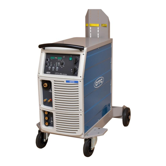
Technische Daten 5.1 Außenansicht CPTX 400 5.2 Außenansicht CPTX 400w/450w CPTX 400/400w/450w Synergy... -
Page 15: Cptx 400/400W/450W Synergy Funktionsbeschreibung
Funktionsbeschreibung 6. CPTX 400/400w/450w Synergy Funktionsbeschreibung Pos. Beschreibung Funktion Schalter AN/AUS Schalter stellt die Maschine ein und aus. Stufenschalter Grobeinstellung des Schweißstroms. Stufenschalter Feinjustierung des Schweißstroms. Taste „Material“, um das Material LED-Leuchten zeigen die derzeit ausgewählten und das Schutzgas auszuwählen. Schweißparameter an (Material und Schutzgas). - Page 16 Funktionsbeschreibung Anzeige der Ist/Soll Schweißspannung (Volt) Spannungsanzeige (Volt) Zusätzlich: Anzeige der Zwischenpausen beim Punkt- und Intervallschweißen (alle 2 Sekunden). Anzeige des Ist/Soll Schweißstroms Wenn die Maschine eingeschaltet wird, wird die Schweißstromanzeige eingestellte Schweißdrahtgeschwindigkeit für 2 Sekunden eingeblendet. Zeigt den Thermo-Schutz an. Gelbe LED-Leuchte Zusätzlich: Angabe der verbrannten AT (Motor-MPZ- Schutz)
-
Page 17: Auswahl Des Schweißmodus
Funktionsbeschreibung 6.1 Auswahl des Schweißmodus Manuelle Synergetische Funktion Einstellung Program 2-Takt-Funktion LED: LM1 LED: LM5 + M1 4-Takt-Funktion LED: LM2 LED: LM5 + LM2 LED: LM1 + LM3 Punktschweißen Intervallschweißen LED: LM1 + LM4 2-Takt-Funktion Intervallschweißen LED: LM2 + LM4 4-Takt-Funktion 6.2 Übersicht der synergetischen Programme G3/4Si1... - Page 18 Funktionsbeschreibung 4. Programwahl: Durch das Drücken der Taste für die Drahtauswahl (Pos.05) und der Taste für die Auswahl des Zusatzmaterials/Schutzgas (Pos.04) werden die entsprechende Dicke des Materials sowie das entsprechende Schutzgas ausgewählt. Falls für die eingestellte Kombination kein entsprechendes Programm existiert, leuchten auf dem Display (Pos.09 &...
-
Page 19: Vorbereitung Des Gerätes Zum Schweißen
Vorbereitung des Gerätes zum Schweißen 7. Vorbereitung des Gerätes zum Schweißen 7.1 Netzanschluss Die CPTX 400/400w/450w Synergy Schweißgeräte sind mit einem Anschlusskabel und Standardstecker für 3x400V und 50Hz ausgerüstet und können an jede, für diese Spannung ausgelegte Steckdose mit entsprechenden Schutzkontakten angeschlossen werden. 7.2 Gasflasche Die Gasflasche mit der zugehörigen Kette befestigen. -
Page 20: Auswahl Der Entsprechenden Vorschubrollen
Schweißen 7.6 Auswahl der entsprechenden Vorschubrollen Der Vorschubmechanismus ist mit 4 Rollen ausgestattet. Bei der Lieferung sind Rollen mit V- Nut mit einem Durchmesser von Ø 1,0-1,2 mm eingebaut. Bei der Änderung des Drahtdurchmessers müssen Sie auch die entsprechende Nut wechseln. Für Stahl und CrNi werden Rollen mit V-Nut genutzt. -
Page 21: Das Einstellen Des Schweißstroms
Schweißen 8.1 Das Einstellen des Schweißstroms Der Schweißstrom wird durch das Drehen der Stufenschalter wie folgt eingestellt: Drehen nach rechts = Erhöhung des Schweißstroms Drehen nach links = Reduzierung des Schweißstroms 8.2 – 2T – (2-Takt Funktion) Wählen Sie mit dem Schalter auf der Frontplatte die 2-Takt Funktion aus. Durch Drücken und Halten des Brennertasters beginnt das Gerät zu schweißen. -
Page 22: Automatischer Softstart
Schweißen 8.6 Automatischer Softstart Bei einer ausreichenden Drahtgeschwindigkeit (min.0, 5 m/min) schaltet sich der Softstart automatisch ein. 8.7 Anti-Stick-Funktion Bei einer ausreichenden Drahtgeschwindigkeit schaltet sich die Anti-Stick-Funktion automatisch ein. Warnung: Während des Schweißvorgangs darf der Schalter für die Schweißstromregulierung nicht umgeschaltet werden. Die Seitentür und der Deckel der Maschine dürfen während des Schweißens nicht geöffnet oder entfernt werden. -
Page 23: Hilfsmittel Zum Schweißen
Hilfsmittel zum Schweißen 9. Hilfsmittel zum Schweißen 9.1. Vorbereitung der Schweißkanten Un-, Niedrig- Hoch- legierter legierter Stahl Stahl CPTX 400/400w/450w Synergy... -
Page 24: Schweißparameter
Hilfsmittel zum Schweißen 9.2 Schweißparameter Warnung Die Angaben in den folgenden Tabellen sind nur Beispielwerte!!! Die optimalen Parametereinstellungen sind immer abhängig von der jeweiligen Schweißform und der Position des Werkstücks. 1. Beispiele für die Schweißparameter mit CO Kehlnaht Blech- Naht- Schweißdraht- Schweiß-... - Page 25 Hilfsmittel zum Schweißen Kehl Naht in der Position „PA“ (nach DIN EN ISO 6947) Schweiβdraht- Schweiβ- Schweiβ- Blech- Naht- Lichtbogen- Gasmenge stärke länge durchmesser strom spannung geschwindihkeit (l/min) t (mm) l (mm) (mm) (cm/min) 2,5 – 3,0 0,9 – 1,0 70 - 100 18 - 19 50 - 60...
- Page 26 Hilfsmittel zum Schweißen Schweißen - einseitig und - zweiseitig Gas- menge Lagen 2 (l/min) Deck Nähte Schweiβdraht- Schweis- Blechstärke Lichtbogen- Gasmenge durchmesser strom Position t (mm) spannung (V) (l/min) (mm) 0,9-1,0 80-100 18-19 10-15 0,9-1,2 100-120 18-20 10-15 1,0-1,2 100-130 18-20...
- Page 27 Hilfsmittel zum Schweißen 2. Beispiele für die Schweißparameter mit CO und Fülldraht: Kehl Naht Schweiβdraht- Schweiβ- Länge Lichtbogen- Schweiβtrom (A) durchmesser geschwindigkeit l (mm) spannung (V) (mm) (cm/min) 3. Beispiele für die Schweißparameter beim MAG-Kurzlichtbogen: Material: Stahl; Gas: Mischung Ar + CO (10-15l/min.) Schweiβdraht Schweiβ-...
-
Page 28: Schweißfehler
Schweißfehler 10. Schweißfehler Fehler Beschreibung Mögliche Ursache Ungleichmäßige Gasabdeckung Empfehlung: 8-10l/min. Schmutz auf dem Poren Werkstück(Fett, Rost, etc.) Zu große Distanz zwischen Brenner und Werkstück oder falsche Handhabung des Brenners Zu hohe Schweißgeschwindigkeit Nicht ausreichende Materialmenge Zu geringer Schweißstrom Ungleichmäßige Führung des Brenners Schlechte Anbindung Zu geringer Schweißstrom... -
Page 29: Wartung
Wartung und Dienstleitung 11. Wartung Unter normalen Arbeitsbedingungen benötigen die CPTX Schweißgeräte sehr geringen Instandhaltungsaufwand. Um eine langjährige Lebensdauer des Gerätes zu gewährleisten, sollten Sie auf folgende Aspekte achten: Zeitweilig muss das Gerät mit Druckluft ausgeblasen werden. Einmal im Jahr müssen die Schweißkabelverbindungen mit der Sekundärwicklung und die Verbindung der Erdklemme überprüft und getestet werden. -
Page 30: Fehlersuche Und Problembehebung
Fehlersuche und Problembehebung 13. Fehlersuche und Problembehebung Fehler Ursache Behebung Die Netzleitung ist beschädigt Die Netzleitung überprüfen Die Netzsicherungen sind Die Sicherungen auswechseln Nach dem durchgebrannt Einschalten funktioniert Der Ein/Aus Schalter des das Gerät nicht Den Schalter auswechseln Geräts ist beschädigt Der Schweißtransformator Den Transformator ist beschädigt... - Page 31 Fehlersuche und Problembehebung Gasflasche leer Gasflasche wechseln Gasdruckminderer defekt Gasdruckminderer tauschen Kein Schutzgas Gasschlauch nicht montiert Gasschlauch montieren Alle anderen Funktionen oder schadhaft oder tauschen vorhanden Schweißbrenner defekt Schweißbrenner wechseln Gasmagnetventil defekt Gasmagnetventil tauschen Falsche Schweißparameter Einstellungen überprüfen Guten Kontakt zum Masseverbindung schlecht Werkstück herstellen Druckminderer, Gasschlauch,...
- Page 32 Fehlersuche und Problembehebung Bremse zu stark eingestellt Bremse lockern Bohrung des Passendes Kontaktrohr Kontaktrohres zu klein verwenden Unregelmäßige Drahtförderseele im Drahtförderseele auf Knicke, Drahtgeschwindigkeit Schweißbrenner defekt Verschmutzung, etc. prüfen Drahtvorschubrollen für Passende verwendeten Schweißdraht Drahtvorschubrollen nicht geeignet verwenden Falscher Anpressdruck der Anpressdruck optimieren Drahtvorschubrollen Schweißbrenner wird...
-
Page 33: Ersatzteilliste Cptx 400 Synergy
Ersatzteilliste CPTX 400 Synergy 14. Ersatzteilliste CPTX 400 Synergy* Bild 2 Bild 1 Bild 3 Bild 4 Bild 3 Bild 4 CPTX 400/400w/450w Synergy... - Page 34 Ersatzteilliste CPTX 400 Synergy CPTX 400 Bild Pos. Beschreibung Synergy 0073-04-0001 Schalter AN/AUS Stufenschalter 1-3 0073-04-0003 Stufenschalter 1-10 0073-04-0002 LED-Leuchten 0072-04-0004 Aufkleber der Frontplatte 0406-04-0004 Potentiometer-Knopf 0403-04-0002 Potentiometer-Knopf 0403-04-0004 Zentralanschluss 0071-04-0013 0071-04-0010 Steckdose Bockrolle 100 0410-04-0004 Bockrolle 200 0410-04-0003 Abdeckkappe 0411-04-0002 Achse 0302-04-0002...
-
Page 35: Schaltplan Cptx 400 Synergy
Ersatzteilliste CPTX 400 Synergy 14.1 Schaltplan CPTX 400 Synergy Steuerplatine Kondensator F1,F2 Sicherung (Träge) F4, F5 Thermoshalter Schütz Drossel Ventilator Elektromotor Schalter mit Lampe Stufenschalter 1-3 Stufenschalter 1-10 Q4-Q6 Taster SLK Varistor Widerstand R3-5 Potentiometer Shunt S1,2 Schalter Transformator Trenntransformator X1-2 Verbinder Gasmagnetventil... -
Page 36: Ersatzteilliste Cptx 400W Synergy
Ersatzteilliste CPTX400w Synergy 15. Ersatzteilliste CPTX 400w Synergy* Bild 2 Bild 1 Bild 3 Bild 4 CPTX 400/400w/450w Synergy... - Page 37 Ersatzteilliste CPTX 400w Synergy CPTX 400w Bild Pos. Beschreibung Synergy Schalter AN/AUS 0073-04-0001 0073-04-0003 Stufenschalter 1-3 Stufenschalter 1-10 0073-04-0002 LED-Leuchten 0072-04-0004 Aufkleber der Frontplatte 0406-04-0006 Potentiometer-Knopf 0403-04-0002 Potentiometer -Knopf 0403-04-0004 Zentralanschluss 0071-04-0014 Schnellanschluss 0071-04-0016 Steckdose 0071-04-0010 Bockrolle160 0410-04-0005 Bockrolle 200 0410-04-0003 0302-04-0002 Abdeckkappe...
- Page 38 Ersatzteilliste CPTX 400w Synergy Seitendeckel rechts 0310-04-0023 Kabelentlaster PG21 0407-04-0003 Netzkabel 0050-04-0064 Seitendeckel links 0310-04-0024 Seitentür 0310-04-0026 Bremseinrichtung 0501-04-0001 Sicherungsgehäuse GU4/GE3 0305-04-0001 0075-04-0001 Sicherung 1AT Träge Sicherung 2AT Träge 0075-04-0002 0075-04-0003 Sicherung 3,15 AT Träge 0073-04-0009 Taster SLK Vorschubmotor 0082-04-0007 Vorschubrolle0,6-0,8 0430-04-0005 0430-04-0006...
-
Page 39: Schaltplan Cptx 400W Synergy
Ersatzteilliste CPTX 400w Synergy 15.1 Schaltplan CPTX 400w Synergy Steuerplatine Kondensator F1,F2,F6 Sicherung (Träge) F4, F5 Thermoshalter Druckschalter Schütz Drossel Ventilator Elektromotor Wasserpumpe KN 33 230V Schalter mit Lampe Stufenschalter 1-3 Stufenschalter 1-10 Q4-Q6 Taster SLK Varistor Widerstand R3-5 Potentiometer Shunt S1,2 Schalter... -
Page 40: Ersatzteilliste Cptx 450W Synergy
Ersatzteilliste CPTX 450w Synergy 16. Ersatzteilliste CPTX 450w Synergy* Bild 1 Bild 2 Bild 3 Bild 4 CPTX 400/400w/450w Synergy... - Page 41 Ersatzteilliste CPTX 450w Synergy CPTX 450w Bild Pos. Beschreibung Synergy Schalter AN/AUS 0073-04-0001 0073-04-0003 Stufenschalter 1-3 Stufenschalter 1-10 0073-04-0002 LED-Leuchten 0072-04-0004 Aufkleber der Frontplatte 0406-04-0005 Potentiometerknopf 0403-04-0002 0403-04-0004 Potentiometerknopf fi23 Zentralanschluss 0071-04-0014 Schnellanschluss 0071-04-0016 0071-04-0005 Steckdose Bockrolle 160 0410-04-0005 Bockrolle 200 0410-04-0003 0411-04-0002 Abdeckkappe...
- Page 42 Ersatzteilliste CPTX 450w Synergy Seitentür 0310-04-0026 0501-04-0001 Bremseinrichtung Sicherungsgehäuse GU4/GE3 0305-04-0001 Sicherung 2AT Träge 0075-04-0002 0075-04-0003 Sicherung 3,15 AT Träge Taster SLK 0073-04-0009 Vorschubmotor 0082-04-0002 0430-04-0006 Vorschubrolle1,0-1,2 0430-04-0007 Vorschubrolle1,0-1,2 Al 0430-04-0005 Vorschubrolle0,6-0,8 Rohr 0431-04-0002 Vorschubmechanismus 0030-04-0009 0030-04-0010 Vorschubmechanismus KPL. Wasserschalter UP-24 0073-04-0013 Schütz KN43 0079-04-0004...
-
Page 43: Schaltplan Cptx 450W Synergy
Ersatzteilliste CPTX 450w Synergy 16.1 Schaltplan CPTX 450w Synergy Steuerplatine Kondensator F1,F2,F6 Sicherung (Träge) F4, F5 Thermoshalter Druckschalter Schütz Drossel Ventilator Elektromotor Wasserpumpe KN 33 230V Schalter mit Lampe Stufenschalter 1-3 Stufenschalter 1-10 Q4-Q6 Taster SLK Varistor Widerstand R3-5 Potentiometer Shunt S1,2 Schalter... -
Page 44: Foreword
Foreword Foreword Thank you for choosing our product. Your new welding equipment from the company OTC DAIHEN EUROPE GmbH offers you the highest quality and latest technology. To exploit the full capabilities of this device and to enjoy it for many years, please read these instructions carefully before connecting and commissioning the device. - Page 45 Foreword Electric and Magnetic Fields During the operations of the welding machine an electromagnetic field (EMF) can be created and may caused health problems. The operator is responsible for the proper installation and use of the device according to the manufacturer’s instructions.
-
Page 46: Regulations For The Prevention Of Accidents
Regulations for the prevention of accidents 1. Regulations for the prevention of accidents The use of welding equipment and welding itself are always associated with a certain security risk. Therefore each set up and operation of the device assumes that the instruction manual is understood and complied. -
Page 47: Operator Protection
Regulations for the prevention of accidents 1.2 Operator protection All people must be protected during the welding process, with appropriate measures against UV radiation, noise, heat and gas pollutants emitted during welding. Never expose yourself to the influences of arc and the hot metal slag without a protective mask and appropriate protection. -
Page 48: Risk Of Poisoning
Regulations for the prevention of accidents 1.4 Risk of poisoning Gases and fumes that are harmful when inhaled for a longer time can be released while welding. Because of this, the following safety guidelines have to be observed: Ensure that you have adequate ventilation for the work area. ... -
Page 49: Transport Of The Power Source
Regulations for the prevention of accidents 1.6 Transport of the power source The unit is generally suitable for transport. The following requirements must be made to ensure an ease transport: The device may only be lifted and transported with the provided handle. ... -
Page 50: Description Of The Welding Equipment
Description and Construction of the welding equipment Dust and cooling system: The device has to be positioned in a way that sufficient air can flow through the cooling fins and the cooling channels. The unit adjusts the cooling system automatically! Please pay attention, that no metal dust can be sucked. -
Page 51: Execution Of The Instruments
Execution of the instruments 4. Execution of the instruments 4.1 The housing The housing is made from high quality steel. The door on the side can be opened easily so that a smooth change of the wire spool is possible. 4.2 The transformer The CPTX400/400w/450w Synergy includes a motor insulation class "F"... -
Page 52: Specifications
Specifications 5. Specifications CPTX 400 CPTX 400w CPTX 450w Item Synergy Synergy Synergy Main voltage 3x400V/50 Hz 3x400V/50 Hz 3x400V/50 Hz Actual power output max. 22,1 kVA 22,1 kVA 26,3 kVA Fuse 25 AT 25 AT 35 AT 17,5 – 54 V 17,5 –... -
Page 53: External View Cptx 400
Specifications 5.1 External view CPTX 400 5.2 External view CPTX 400w/CPTX 450w CPTX 400/400w/450w Synergy... -
Page 54: Description Of The Functions (Cptx 400/400W/450W Synergy)
Function description 6. Description of the functions (CPTX 400/400w/450w Synergy) Pos. Description Function Switch ON/OFF Turnes the maschine on and off. Step switch Rough adjustment of the welding current. Step switch Fine adjustment of the welding current. Button “Material”, to choose the LED shows the currently selected welding parameters material and the shielding gas. - Page 55 Function description Indicator of the actual/nominal welding voltage. Voltmeter In addition: Indicator of the breaks for the spot- and interval-welding (every 2 seconds). Indicator of the actual/nominal welding current. Welding current display When the device is switched on, the set welding wire speed is displayed for 2 seconds.
-
Page 56: Choise Of The Welding Mode
Function description 6.1 Choise of the welding mode Function Manual settings Synergic program 2-stroke-mode LED: LM1 LED: LM5 + M1 4-stroke-mode LED: LM2 LED: LM5 + LM2 LED: LM1 + LM3 Spot-welding Interval-welding LED: LM1 + LM4 2-stroke-mode Interval-welding LED: LM2 + LM4 4-stroke-mode 6.2 Overview of the synergic programs G3/4Si1... - Page 57 Function description 4. Program setting: By pressing the button for the wire selection (Pos.05) and the button for the material/shielding gas selection (Pos.04) you can choose the thickness of your material and the corresponding shielding gas. If there doesn’t exist a corresponding program for your chosen combination, each display (Pos.09 &...
-
Page 58: Preparations For Welding
Preparations for welding 7. Preparations for welding 7.1 Power connection The CPTX 400/400w/450w Synergy welder are equipped with a standard cable and plug for 3x400V and 50Hz, and can be connected to any, for this voltage designed socket contacts which are connected with appropriate protection. 7.2 Gas cylinder Attach the gas cylinder with the chain at the rear of the unit. -
Page 59: Selection Of The Appropriate Feed Rolls
Welding 7.4 Selection of the appropriate feed rolls The feed mechanism is equipment with 4 rolls. Upon delivery rolls with V-groove with a diameter of 1.0-1.2 mm are attached. With the change of the wire diameter you have to replace a corresponding groove. For steel and CrNi rolls with V-groove are used. If you want to weld with flux cored wire you have to use rolls with a U-groove. -
Page 60: 2T - (2-Stroke Mode)
Welding 8.2 – 2T – (2-stroke mode) Please choose the 2-stroke mode with the switch on the front panel. Pressing and holding the torch switch starts the unit to weld on. To stop the welding process, please release the torch switch. 8.3 –... - Page 61 Welding Warning: During the welding process the switch for the regulation of welding current should not be changed. The side door and the top panel of the power source should not be opened or removed during the welding process. When exceeding the set welding time or in case of overheating, the thermostat of the machines switches off automatically (the yellow light is on and only the ventilator is rotating).
-
Page 62: Additives For The Welding Operation
Additives for the welding operation 9. Additives for the welding operation 9.1 Preparation of the toes Stainless Carbon steel Shape of seam steel CPTX 400/400w/450w Synergy... -
Page 63: Welding Parameters
Additives for the welding operation 9.2 Welding parameters Warning The information in the tables below are for example purposes only! The optimum parameter settings are always depending on the weld shape and the position of the workpiece. 1. Examples for the welding parameters with CO ... - Page 64 Additives for the welding operation Corner weld in position „PA“ (after DIN EN ISO 6947) Thickness Diameter of Welding Welding Flow Arc voltage of the steel length the welding current speed t (mm) l (mm) wire (mm) (cm/min) (l/min) 2,5 –...
- Page 65 Additives for the welding operation Welding of on side- and double undercuts Thick- Diameter ness of the Shape Welding Welding speed Flow Co Laps of the g (mm) welding (mm) current voltage (cm/min) (l/min) steel wire (mm) t(mm) Overlap welds Thickness Diameter of the Welding...
- Page 66 Additives for the welding operation 2. Examples for the welding parameters with CO and cored wire: Corner welding Diamter of the Length Welding current Welding speed welding wire Arc voltage (V) l (mm) (cm/min) (mm) 3. Examples for the welding parameters for the MAG-short-circuit arc: ...
-
Page 67: Welding Defects
Welding defects 10. Welding defects Defect Description Possible causes Irregular flow of the gas. Suggestion: 8-10l/min. No or too less shielding gas. Porosities Dirt on the Workpiece (grease, rust, etc.). To long distance between the welding torch and the workpiece or mishandling of the welding torch. -
Page 68: Maintenance
Maintenance and Service 11. Maintenance Under normal operating conditions the CPTX 400/400w/450w Synergy requires very little maintenance operations. To ensure a longtime durability, you should pay attention to the following aspects: Temporary the device must be blown out with compressed dry air. ... -
Page 69: Troubleshooting
Troubleshooting 13. Troubleshooting Failure Cause Repair The power line Check the power line is damaged The fuses are blown Replace the fuses After switching on, the power source doesn’t work The On/Off switch is Replace the On/Off switch damaged The welding transformer is Replace the welding damaged transformer... - Page 70 Troubleshooting Gas cylinder is empty Change the gas cylinder Gas pressure regulator Change the gas pressure is defect regulator No shielding gas Gas hose not installed Install or change the All other functions available or defect gas hose Welding torch defect Change the welding torch Gas valve defect Change the gas valve...
- Page 71 Troubleshooting Brake is set too tight Loose the brake Whole of the contact tip to Use an appropriate small contact tip The wire liner in the torch is Check the wire liner for Irregular wire speed broken breaks, dirt, etc. Wire feed rolls used for Use suitable wire feed rollers welding wire is not suitable...
-
Page 72: Spare Part List Cptx 400 Synergy
Spare part list CPTX 400 Synergy 14. Spare part list CPTX 400 Synergy* Figure 2 Figure 1 Figure 3 Figure 4 Bild 3 Bild 4 CPTX 400/400w/450w Synergy... - Page 73 Spare part list CPTX 400 Synergy CPTX 400 Figure Pos. Description Synergy Switch ON/OFF 0073-04-0001 0073-04-0003 Stepping switch 1-3 Stepping switch 1-10 0073-04-0002 LED-lamps 0072-04-0004 Label of the front panel 0406-04-0004 0403-04-0002 Potentiometer-Button Potentiometer-Button 0403-04-0004 Main cable 0071-04-0013 Electrical socket 0071-04-0010 Wheel 100 0410-04-0004...
-
Page 74: Connection Diagram Cptx 400 Synergy
Spare part list CPTX 400 Synergy 14.1 Connection diagram CPTX 400 Synergy Control board Condenser F1,F2 Fuse F4, F5 Thermostat Contactor Choke Ventilator Electric motor Switch with lamp Step switch 1-3 Step switch 1-10 Q4-Q6 Feeler SLK Varistor Resistor R3-5 Potentiometer Shunt S1,2... -
Page 75: Spare Part List Cptx 400W Synergy
Spare part list CPTX 400w Synergy 15. Spare part list CPTX 400w Synergy* Figure 2 Figure 1 Figure 3 Figure 4 CPTX 400/400w/450w Synergy... - Page 76 Spare part list CPTX 400w Synergy CPTX 400w Figure Pos. Description Synergy Switch ON/OFF 0073-04-0001 0073-04-0003 Stepping switch 1-3 Stepping switch 1-10 0073-04-0002 LED-lamps 0072-04-0004 Label of the front panel 0406-04-0006 Potentiometer-Button 0403-04-0002 Potentiometer -Button 0403-04-0004 Main cable 0071-04-0014 Quick connector 0071-04-0016 Electrical socket 0071-04-0010...
- Page 77 Spare part list CPTX 400w Synergy Side cap right 0310-04-0023 Cable discharger PG21 0407-04-0003 Power cable 0050-04-0064 Side cap left 0310-04-0024 Side door 0310-04-0026 Stopping device 0501-04-0001 Fuse Housing GU4/GE3 0305-04-0001 0075-04-0001 Fuse 1AT Fuse 2AT 0075-04-0002 0075-04-0003 Fuse 3,15 AT 0073-04-0009 Feeler SLK Feed mechanism motor...
-
Page 78: Connection Diagram Cptx 400W Synergy
Spare part list CPTX 400w Synergy 15.1 Connection diagram CPTX 400w Synergy Control board Condenser F1,F2,F6 Fuse F4, F5 Thermostat Press switch Contactor Choke Ventilator Electric motor Water pump KN 33 230V Switch with lamp Step switch 1-3 Step switch 1-10 Q4-Q6 Feeler SLK Varistor... -
Page 79: Spare Part List Cptx 450W Synergy
Spare parts list CPTX 450w Synergy 16. Spare part list CPTX 450w Synergy* Figure 1 Figure 2 Figure 3 Figure 4 CPTX 400/400w/450w Synergy... - Page 80 Spare part list CPTX 450w Synergy CPTX 450w Figure Pos. Descrption Synergy Switch ON/OFF 0073-04-0001 0073-04-0003 Stepping switch 1-3 Stepping switch 1-10 0073-04-0002 LED-lamps 0072-04-0004 Label of the front panel 0406-04-0005 Potentiometer-Button 0403-04-0002 0403-04-0004 Potentiometer-Button Main cable 0071-04-0014 Quick connector 0071-04-0016 0071-04-0005 Electrical socket...
- Page 81 Spare part list CPTX 450w Synergy Side door 0310-04-0026 0501-04-0001 Stopping device Fuse housing GU4/GE3 0305-04-0001 Fuse 2AT 0075-04-0002 0075-04-0003 Fuse 3,15 AT Feeler SLK 0073-04-0009 Feed mechanism motor 0082-04-0002 0430-04-0006 Wire feed roll1,0-1,2 0430-04-0007 Wire feed roll1,0-1,2 Al 0430-04-0005 Wire feed roll0,6-0,8 Tube 0431-04-0002...
-
Page 82: Connection Diagram Cptx 450W Synergy
Spare part list CPTX 450w Synergy 16.1 Connection diagram CPTX 450w Synergy Control board Condenser F1,F2,F6 Fuse F4, F5 Thermostat Press switch Contactor Choke Ventilator Electric motor Water pump KN 33 230V Switch with lamp Step switch 1-3 Step switch 1-10 Q4-Q6 Feeler SLK Varistor...
Need help?
Do you have a question about the Synergy CPTX 400 and is the answer not in the manual?
Questions and answers