Advertisement
Quick Links
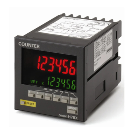
Multifunction Counter
H7BX
DIN 72×72 mm Multifunction Counter with a Bright,
Easy-to-view, Negative Transmissive LCD.
• Highly visible display with backlit transmissive LCD.
• Selectable display color (red/green) enables checking output status at a
distance.
• Easy operation with a key for each digit.
• Perform all basic settings with a DIP switch.
• Provides a total and preset counter, batch counter, dual counter, and
tachometer (See note.).
• Wide range of inputs accepted for NPN/PNP inputs (multi-inputs) and 2-
wire DC sensors.
• Complies with UL, CSA, and CE marking.
• Degree of protection: IP54 equivalent (front section only).
Note: The functions that can be selected depend on the model.
Ordering Information
■ List of Models
External power supply
Contact and
12 VDC
NPN transistor output
■ Accessories (Order Separately)
Name
Soft Cover
Hard Cover
Terminal Cover (See note.)
Note: Supplied with the H7BX.
Output type
Supply voltage
100 to 240 VAC
24 VAC/12 to 24 VDC
Model
Y92A-72F1
Y92A-72
Y92A-72T
Be sure to read Safety Precautions on page 25.
1-stage
H7BX-A
H7BX-AD1
H7BX
Multifunction Counter
2-stage
H7BX-AW
H7BX-AWD1
1
Advertisement

Subscribe to Our Youtube Channel
Related Manuals for Omron H7BX-AD1


Summary of Contents for Omron H7BX-AD1
- Page 1 Supply voltage 1-stage 2-stage 100 to 240 VAC H7BX-A H7BX-AW Contact and 12 VDC NPN transistor output 24 VAC/12 to 24 VDC H7BX-AD1 H7BX-AWD1 ■ Accessories (Order Separately) Name Model Soft Cover Y92A-72F1 Hard Cover Y92A-72 Terminal Cover (See note.) Y92A-72T Note: Supplied with the H7BX.
- Page 2 Operating voltage range 85% to 110% of rated supply voltage (90% to 110% at 12 VDC) H7BX-A/AW: 9.6 VA max. (100 to 240 VAC) Power consumption H7BX-AD1/AWD1: 8 VA max. (24 VAC), 5.3 W max. (12 to 24 VDC) Mounting method Flush mounting...
- Page 3 ■ Characteristics ● Electrical Life Expectancy Insulation resis- 100 MΩ min. (at 500 VDC) between current-carrying terminal and exposed non- (Reference Values) tance current-carrying metal parts, and between non-continuous contacts Resistive Load Between current-carrying metal parts and non-current-carrying metal parts: 2,000 VAC, 50/60 Hz for 1 min 1,000 Between power supply and input circuit: 2,000 VAC, 50/60 Hz for 1 min (for models...
- Page 4 ■ I/O Functions ● Using as a Counter (See note 1.) ● Using as a Tachometer (1) All Modes Except for Dual Counter Mode Reads counting signals. CP1, • Reads count signals. (CP2 input is not • Increment, decrement, up/down (command, individual, or quadrature) inputs available.) CP1, CP2 can be used.
- Page 5 (−) External power supply External power supply Unused. Unused. Unused. OUT1 OUT2 protection protection OUT2 OUT1 H7BX-AD1 H7BX-AWD1 10 11 12 13 14 10 11 12 13 14 (−) (−) External power supply External power supply Unused. Unused. Unused. OUT1...
- Page 6 ■ Input Connections A no-voltage input (short-circuit or open) or voltage input can be selected for each input. (The key protection input is always a no-voltage input (NPN input)). ● No-voltage Inputs (NPN Inputs) Open Collector Voltage Output Contact Input DC Two-wire Sensor Sensor or sensor...
- Page 7 Nomenclature Indicators Operation Keys A Reset Indicator I Mode Key (Orange) Lit when the reset input (1) or reset key is ON. Used to switch mode and setting items. B Key Protection Indicator J Reset Key (Orange) C Control Output Indicator K Up Keys: (Orange) OUT:...
- Page 8 Operating Procedures ■ Setting Procedure Guide Settings for Counter Operation (1-stage/2-stage Counter, Total and Preset Counter, Batch Counter, Dual Counter) ● Using Basic Settings Only Basic Settings The settings can be made • Counting speed (30 Hz, 5 kHz) easily with the DIP switch. •...
- Page 9 Operating Procedures (Counter Function) ■ Settings for Basic Operations Settings for basic functions can be performed with just the DIP switch. Be sure to turn ON pin 1 when using the DIP switch. Item DIP switch settings enable/disable Disabled Enabled Pin 4 Pin 5 Output mode...
- Page 10 When using the H7BX as a Total and Preset Counter, Batch Counter, or Dual Counter, switch the configuration using the procedure on page 23. ■ Setting Advanced Functions Settings that cannot be performed with the DIP switch are performed with the operation keys. Power ON For details on operations and display in run mode, refer to page 12.
- Page 11 ■ Explanation of Functions Settings marked with a star can be performed with the DIP switch. • Input Mode (cntm) ★ • Reset Input Signal Width (iflt) ★ Set increment mode (UP), decrement mode (DOWN), or one of Set the reset input signal width (20 ms/1 ms) for reset/reset 1 the increment/decrement modes (UP/DOWN A, UP/DOWN B, or and total reset/reset 2 inputs together.
- Page 12 ■ Operation in Run Mode • Set the number for each digit with the Keys. ● 1-stage Counter • Present Value Present value Shows the present count value. Set value • Set Value (Set Value 1, Set Value 2) Set the set value. ●...
- Page 13 ■ Input Modes and Present Value (See note 1.) UP (Increment) Mode DOWN (Decrement) Mode CP1: Count input; CP2: Prohibit input CP1: Count input; CP2: Prohibit input Prohibit Prohibit n−1 n−2 Present Present n−3 value value n−4 n−5 must be greater than the minimum signal width. (See note 2.) must be greater than the minimum signal width.
- Page 14 ■ Input/Output Mode Settings One-shot output from OUT1 (The one-shot output time Operation for 1-stage models is the same as that for OUT2. can be set in the range When using a 2-stage model as a 1-stage counter, total and preset counter, 0.01 to 99.99s.) Self-holding Self-holding...
- Page 15 One-shot output from OUT1 (The one-shot output time can be set in the range 0.01 to 99.99s.) Self-holding Self-holding One-shot output output output from OUT2 Input mode Operation after count completion DOWN UP/DOWN A, B, C The present value display does not change during the Reset/ one-shot output time...
- Page 16 (The one-shot output time can be set in the range 0.01 to 99.99s.) Self-holding Instanta- One-shot output neous output (equals) output Input mode Operation after count completion UP/DOWN A, B, C Reset/reset 1 999999 Set value 2 The display continues to increase/ Set value 1 decrease until the overflow or underflow value is reached.
- Page 17 ● Total and Preset Counter Operation The H7BX has a total counter separate from the 1-stage preset counter for counting the total accumulated value. • The total counter continues to count the total Reset/reset 1 accumulated value when the present value is reset using reset/reset 1 input (Reset Key).
- Page 18 ■ Reset Function List 1-stage/2-stage Function Total and preset counter Batch counter Dual counter counter Batch count Dual count CP1 present Display in run Present value/set Present value/ Total count Present value/ value/batch value/dual count value/CP2 mode value (1, 2) set value value set value...
- Page 19 Operating Procedures (Tachometer Function) (H7BX-AW@ only) ■ Switching from Counter to Tachometer The H7BX is factory-set to the 2-stage counter configuration. To switch to the Power ON tachometer configuration, use the procedure shown on the right. For details, refer to page 23. Configuration selection mode Run mode Note: Hold down the...
- Page 20 When the H7BX using as a tachometer, switch to the tachometer configuration using the procedure given on page 23. ■ Settings for Advanced Functions Settings that cannot be performed with the DIP switch are performed with the operation keys. Power ON For details on operations in run mode, refer to page 22.
- Page 21 ■ Explanation of Functions Settings marked with a star can be performed with the DIP switch. • Tachometer Output Mode (totm) ★ • Auto-zero Time (avt) ★ Set the output method for control output based on the OUT1/ It is possible to set the H7BX so that if there is no pulse for a OUT2 set value.
- Page 22 ■ Operation in Run Mode • Set the number for each digit with the Keys. • Measurement Value Measurement value Displays the currently measured value. • OUT1/OUT2 Set Value Set OUT1 set value and OUT2 set value. The Measurement value measurement value is compared to OUT1 set value and OUT2 set value and output is made according to OUT1 set value...
- Page 23 ■ Switching between Using a Preset Counter, Total and Preset Counter, Batch Counter, Dual Counter, and Tachometer Select which H7BX configuration to use (i.e., preset counter, total and preset counter, batch counter, dual counter, or tachometer) in the configuration selection mode. The H7BX is also equipped with a DIP switch monitor function, a convenient function that enables the settings of the DIP switch pins to be confirmed using the front display.
- Page 24 ■ Key Protect Level When the key-protect switch is set to ON, it is possible to prevent setting errors by prohibiting the use of certain operation keys by specifying the key protect level (KP-1 to KP-5). The key protect indicator is lit while the key-protect switch is set to ON. Confirm the ON/ OFF status of the key protect switch after the H7BX is mounted to the panel.
- Page 25 Safety Precautions supply capacity, operation may not start. Be sure to use a Caution power supply with a sufficient capacity. • Use a commercial power supply as the AC power supply for Minor injury due to electric shock may occasionally the H7BX.
- Page 26 Precautions for Correct Use • Inrush current generated by turning ON or OFF the power supply may deteriorate contacts in the power supply circuit. Turn ON or OFF using a device with a rated current of 10 A or higher. •...
- Page 27 Warranty and Limitations of Liability WARRANTY OMRON's exclusive warranty is that the products are free from defects in materials and workmanship for a period of one year (or other period if specified) from date of sale by OMRON. OMRON MAKES NO WARRANTY OR REPRESENTATION, EXPRESS OR IMPLIED, REGARDING NON-INFRINGEMENT, MERCHANTABILITY, OR FITNESS FOR PARTICULAR PURPOSE OF THE PRODUCTS.
- Page 28 To convert millimeters into inches, multiply by 0.03937. To convert grams into ounces, multiply by 0.03527. Cat. No. M077-E1-01 In the interest of product improvement, specifications are subject to change without notice. OMRON Corporation Industrial Automation Company Control Devices Division H.Q.
- Page 29 New Product Multifunction Counter/Tachometer H7CX-@ Ultra-compact Counter Provides More Complete Functionality. Basic Features • Short body with depth of only 59 mm (for 12 to 24-VDC Models with Screw Terminals). • Better readability with character height of 12 mm on 4-digit models and 10 mm on 6-digit models.
- Page 30 H7CX-@-N Other Features Key Protection Select from any of seven protection patterns. Use the best one for the The front color can be changed simply by application. replacing the Front Panel. New Functions The Front Panel can be replaced with an optional Front Panel (sold separately) with a different color to match the installation site.
- Page 31 H7CX-@-N Model Number Legend (Not all possible combinations of functions are available.) H7CX-@@@@@@-N 1 2 3 4 5 6 1. Type 2. External connections 3. Digits Symbol Meaning Symbol Meaning Symbol Meaning Standard type None Screw terminals None 6 digits Tachometer 11-pin socket 4 digits...
- Page 32 H7CX-@-N Accessories (Order Separately) Front Panels (Replacement Part) Model Color Applicable Counters Page Y92P-CXC4G Light gray (5Y7/1) 4-digit Counter Y92P-CXC4S White (5Y9.2/0.5) Y92P-CXC4B Black (N1.5) Y92P-CXC6G Light gray (5Y7/1) 6-digit Counter Y92P-CXC6S White (5Y9.2/0.5) Y92P-CXC6B Black (N1.5) Note: 1. You can change the color of the Front Panel when mounting the Counter. The Counter is shipped with a black (N1.5) Front Panel. 2.
- Page 33 H7CX-A@-N H7CX-A@-N Multifunction Preset Counter • Easy to check the output status from a long distance with changing display colors (red, green, and orange). • Includes total and preset counter, batch counter, dual counter, twin counter, and tachometer. *1. Not supported by the H7CX-A11@-N. *2.
- Page 34 Immunity Voltage Dip/Interruption: EN 61000-4-11: 0.5 cycle, 100% (rated voltage) * The following safety standards apply to models with sockets (H7CX-A11@ or H7CX-A114@). cUL (Listing): Applicable when an OMRON P2CF(-E) Socket is used. cUR (Recognition): Applicable when any other socket is used.
- Page 35 H7CX-A@-N I/O Functions Using as a Counter (1) In general (except for Dual Counter Mode) • Reads counting signals. • Increment, decrement, command, individual, and quadrature inputs accepted. CP1, CP2 (2) When used as a dual counter or twin counter •...
- Page 36 H7CX-A@-N Connections Terminal Arrangement Confirm that the power supply meets specifications before use. H7CX-A-N/-A4-N H7CX-AD-N/-A4D-N H7CX-AS-N/-A4S-N 1-stage Contact Output 1-stage Contact Output 1-stage Transistor Output (−) (−) Sensor Sensor 12 VDC 12 VDC External External power supply power supply (−) Terminals 1 and 6 are connected internally.
- Page 37 H7CX-A@-N Block Diagram Input Circuits CP1, CP2, Reset/Reset 1, and Total Reset/Reset 2 (Basic insulation) Power supply Input Output circuit circuit (Basic insulation) (See note.) No-voltage Inputs Voltage Inputs (PNP Inputs) Display circuit (NPN Inputs) Internal Input circuits control circuit Key switch +14V circuit...
- Page 38 H7CX-A@-N Nomenclature Display Section Operation Keys 1. Key Protect Indicator (orange) 10. Mode Key (Changes modes and setting items.) 2. Control Output Indicator (orange) 11. Reset Key (See note.) OUT: (One-stage) OUT: (Two-stage) 12. Up Keys 3. Reset Indicator (orange) (6-digit models: (Lit when the reset input (1) or Reset Key is ON.) Displayed only when the configuration selection...
- Page 39 H7CX-A@-N H7CX-AD-N/-ASD-N/-AWSD-N/-A4D-N/-A4SD-N/-A4WSD-N (Flush Mounting Models) 48 × 48 44.8 × 44.8 Note: M3.5 terminal screw (effective length: 6 mm) H7CX-A11-N/-A11S-N/-A11D1-N/-A11SD1-N/-A114-N/-A114S-N/-A114D1-N (Flush Mounting/Surface Mounting Models) 14.4 48 × 48 63.7 44.8 × 44.8 Dimensions with Flush Mounting Adapter H7CX-A-N/-AS-N/-AW-N/-AWS-N/-AWD1-N/-AWSD1-N/-A4-N/-A4S-N/-A4W-N Panel Cutouts Panel cutouts are as shown below.
- Page 40 H7CX-A@-N Accessories (Order Separately) Soft Cover Hard Cover Note: Depending on the operating environment, the condition Y92A-48F1 Y92A-48 of resin products may deteriorate, and may shrink or become harder. Therefore, it is recommended that resin products are replaced regularly. Front Panel (Replacement Part) You can change the color of the Front Panel when mounting the Protecting the Counter/Tachometer in Environments Counter/Tachometer.
- Page 41 H7CX-A@-N Connection Sockets Front Connecting Socket Terminal arrangement Mounting hole Model Dimensions and internal connections dimensions P2CF-11 31.2 max. 50 max. Two, 4.5-dia. holes 70 max. Two, M4 or 4.5-dia. holes Eleven, M3.5 × 7.5 sems screws ±0.2 P2CF-11-E 50 max. 31.2 max.
- Page 42 H7CX-A@-N Optional Products for Track Mounting Mounting Track ±0.15 PFP-100N PFP-50N ±0.3 ±0.15 15 (5)* 1,000 (500)* * The values shown in parentheses are for the PFP-50N. Mounting Track PFP-100N2 ±0.3 29.2 1,000 End Plate PFP-M M4 × 8 pan head screw 35.5 35.3 11.5...
- Page 43 H7CX-A@-N Counter Operating Procedures Setting Procedure Guide Setting for Counter Operation Use the following settings. Setting for Tachometer Operation Refer to page page 27. * At the time of delivery, the H7CX is set to the 1-stage preset counter configuration. (2-stage models are set to the 2-stage preset counter configuration.) Refer to page page 35 for information on switching models.
- Page 44 H7CX-A@-N Counter Step3 Parameters that cannot be set with the DIP switch are set with the operation keys on the front panel. Change to Function Setting Mode. Power ON For details on operations and display in run mode, refer to page page 20. 3 s min.
- Page 45 H7CX-A@-N Counter To previous From previous page page Absolute value • Make the absolute value setting and forecast setting using the U (D) Keys. setting/forecast value setting (SETM) ofst (ABS) (OFST) Note: Displayed only when the configuration selection mode is set to the 2-stage function 2cnt. Set value •...
- Page 46 H7CX-A@-N Counter Explanation of Functions Items marked with stars ★ can be set using the DIP switch. Input Mode (cntm)★ Prescale Value (pscl) Set increment mode (UP), decrement mode (DOWN), or one of the Pulses input to the counter are converted according to the specified increment/decrement modes (UP/DOWN A, UP/DOWN B, or UP/ prescale value.
- Page 47 H7CX-A@-N Counter Absolute Value Setting/Forecast Value Setting (setm) Output ON Count Alarm Set Value (on-a) For the 2 count output mode, an absolute value setting (abs) or Set the alarm value for the output ON count. The limit can be set to between 0 × 1000 (0 times) and 9999 × 1000 forecast value setting (ofst) can be set for set value 1.
- Page 48 H7CX-A@-N Counter Operation in Run Mode I/O Functions for Counter Operation • Set values for each digit as required using the U Keys. (U Key only for 6-digit models.) 1-stage Preset Counter Total and Preset Counter Dual Counter Present value Set value Present value Dual count value...
- Page 49 H7CX-A@-N Counter Input Modes and Present Value (See note 1.) I/O Functions for Counter Operation UP (Increment) Mode DOWN (Decrement) Mode CP1: Count input; CP2: Prohibit (gate) input CP1: Count input; CP2: Prohibit (gate) input Prohibit Prohibit n−1 n−2 Present value Present value n−3 n−4...
- Page 50 H7CX-A@-N Counter Input/Output Mode Settings I/O Functions for Counter Operation If a 1-stage model or 2-stage model is incorrectly used as twin counter, the operation for One-shot output from OUT1 output 2 will be performed. When using a 2-stage model as a 1-stage preset counter, (The one-shot output time can be set in the range 0.01 to 99.99s.) total and preset counter, or dual counter, OUT1 and OUT2 turn ON and OFF...
- Page 51 H7CX-A@-N Counter One-shot output from OUT1 (The one-shot output time ca set in the range 0.01 to 99.9 Self-holding Self-holding One-shot output output output from OUT2 Input mode Operation after count completion DOWN UP/DOWN A, B, C The present value display does not Reset/ change during the...
- Page 52 H7CX-A@-N Counter (The one-shot output time can be set in the range 0.01 to 99.99s.) Self-holding Instantaneous One-shot output (equals) output output Input mode Operation after count completion UP/DOWN A, B, C Reset/ reset 1 999999 Set value 2 The display continues to increase/ Set value 1 decrease until the overflow or underflow value is reached.
- Page 53 H7CX-A@-N Counter Total and Preset Counter Operation The H7CX has a total counter, separate from the 1-stage preset counter, for counting the total accumulated value. • The total counter continues to count the total Reset/reset 1 accumulated value when the present value is reset using reset/reset 1 input (Reset Key).
- Page 54 H7CX-A@-N Counter Twin Counter Operation Two independent counters are built in. Counter 1 Counter 2 Counter input Reset input Reset 1 Reset 2 Counter 1 display Counter 2 display Counter 1 present value Counter 2 present value Present value display and setting Switched with Key.
- Page 55 H7CX-A@-N Tachometer Setting Procedure Guide Tachometer Operation Step1 The H7CX is factory-set to the 2-stage counter configuration (1-stage counter configuration for H7CX-AU@-N models). Enter configuration selection mode using the following chart and set the tachometer mode. Note: can be performed first, followed by Step2 Step1 Configuration...
- Page 56 H7CX-A@-N Tachometer Step3 Parameters that cannot be set with the DIP switch are set with the operation keys on the front panel. Change to Function Setting Mode. For details on operations and display in run mode, refer to page page 33. Power ON 3 s min.
- Page 57 H7CX-A@-N Tachometer To previous From previous page page NPN/PNP • Set the NPN/PNP input mode using the U Key. input mode (IMOD) (NPN input) (PNP input) Display • Set the display color using the U Key. color (COLR) (Red) (Green) (Orange) (Red-green) (Green-red) (Red-orange) (Orange-red) (Green-orange) (Orange-green) Peak/bottom •...
- Page 58 H7CX-A@-N Tachometer Explanation of Functions Tachometer Operation Items marked with stars ★ can be set using the DIP N: Number of pulses per revolution d: Diameter of rotating body (m) switch. d: Diameter πd: Circumference (m) Tachometer Input Mode (tinm) of rotating body (m) Set the count input mode to one of the following: 1 input (F1), 2 inputs...
- Page 59 H7CX-A@-N Tachometer NPN/PNP Input Mode (imod)★ Output Hysteresis (hys) Select either NPN input (no-voltage input) or PNP input (voltage This setting can be used to prevent output chattering if the input) as the input format. measurement value fluctuates slightly near the set value. When using a two-wire sensor, select NPN input.
- Page 60 H7CX-A@-N Tachometer ON Count Alarm Set Values for Outputs 1 and 2 (OUT1 and OUT2) (on1a and on2a) Set the ON count alarm values for the outputs 1 and 2. The limit can be set to between 0 × 1000 (0 times) and 9999 × 1000 (9,999,000 times).
- Page 61 H7CX-A@-N Tachometer Operation in Run Mode Tachometer Operation • Set each digit using the individual U Keys. • Measurement value Measurement value Displays the currently measured value. • Comparison value 1/Comparison value 2 Set comparison value 1 and comparison value 2. Measurement value 1 The measurement value is compared to comparison value 1 and comparison value 2 and...
- Page 62 H7CX-A@-N Output Mode Setting and Operation Tachometer Operation Input mode Output mode Operation setting setting (Upper-limit) Comparison value 2 Measurement value Upper and (Lower-limit) ON condition for OUT1: Measurement value ≤ Comparison value 1 Comparison value 1 lower limit ON condition for OUT2: Measurement value ≥ Comparison value 2 (HI-LO) OUT1 OUT2...
- Page 63 H7CX-A@-N Switching between Preset Counter, Total and Preset Counter, Batch Counter, Dual Counter, Twin Counter, and Tachometer Operation Select which H7CX configuration is used (i.e., preset counter, total and preset counter, batch counter, dual counter, twin counter, or tachometer) in configuration selection mode. The H7CX is also equipped with a DIP switch monitor function, a convenient function that enables the settings of the DIP switch pins to be confirmed using the display on the front of the H7CX.
- Page 64 H7CX-A@-N Key Protect Level It is possible to prevent setting errors by prohibiting the use of certain operation keys by specifying the key protect level (KP-1 to KP-7) when the key-protect switch is set to ON. The key protect level is set in the function setting mode. The key protect indicator is lit when the key-protect switch is ON. (Disable) (Enable) *Factory-set to OFF...
- Page 65 H7CX-R@-N H7CX-R@-N Tachometer • Tachometer-only model (DIN 48 × 48) for the H7CX (Supports display and alarm outputs for numbers of rotations, speed, and flow rate.) • Socket design allows either flush or surface mounting. • “-W” models added for control with two independent measurements. •...
- Page 66 Immunity Voltage Dip/Interruption: EN61000-4-11: 0.5 cycle, 100% (rated voltage) * The following safety standards apply to the H7CX-R11@. cUL (Listing): Applicable when an OMRON P2CF(-E) Socket is used. cUR (Recognition): Applicable when any other socket is used. I/O Functions Count, count 1, Reads counting signals.
- Page 67 H7CX-R@-N Connections Terminal Arrangement Block Diagram H7CX-R11-N (Basic insulation) Power supply H7CX-R11D1-N Output circuit circuit Hold (Basic insulation) (Basic insulation) Count Display circuit Hold Internal circuit Internal Input circuits Hold control circuit Key switch circuit (−) Sensor 12 VDC Input Circuits External power supply (−)
- Page 68 H7CX-R@-N Input Connections The inputs of the H7CX-R are no-voltage (short-circuit or open) inputs or voltage inputs. They are set for use as voltage inputs at the time of delivery. No-voltage Inputs (NPN Inputs) Open Collector Voltage Output Contact Input DC Two-wire Sensor PLC or Sensor,...
- Page 69 H7CX-R@-N Nomenclature Display Section Operation Keys 1. Hold Indicator (orange) 7. Mode Key (Lit when the hold input or hold key is ON. ) (Used to switch mode and setting items.) 2. Key Protect Indicator (orange) 8. Hold Key Lit when the key protect switch is ON. (Used to sustain the measurement value and output.) 3.
- Page 70 H7CX-R@-N Accessories (Order Separately) Flush Mounting Y92F-45 Adapter Note: Depending on the operating environment, the condition Use this Adapter to install the Y92F-30 of resin or rubber products may deteriorate, or they may Counter/Tachometer in a cutout shrink or become harder. Therefore, it is recommended Order a Flush Mounting Adapter previously made for a DIN 72 ×...
- Page 71 H7CX-R@-N Operating Procedures Parameters must be set using both the DIP switch and the operation keys on the front panel. Refer to the following for the detailed procedure. Step1 Set the basic parameters. 1 2 3 4 5 6 7 8 (Factory setting) Counting speed/ Item...
- Page 72 H7CX-R@-N Step2 For details on operations in run mode, refer to page page 47. Change to Function Setting Mode. *1 If the mode is switched to the function setting mode during operation, operation will Power ON continue. *2 Changes made to settings in function setting mode are enabled for the first time when the mode is changed to run mode.
- Page 73 H7CX-R@-N Explanation of Functions Advanced Functions Decimal Point Position (dp) Basic Functions Decide the decimal point position for the measurement value and Input Mode comparison value. The mode can be switched between tachometer mode and AMD- compatible mode. Prescale Value (pscl) Tachometer Mode It is possible to display the rate of rotation or the speed of a device or machine to which the H7CX is mounted by converting input pulses to...
- Page 74 H7CX-R@-N Startup Time (stmr) Key Protect Level (ypt) In order to prevent undesired output resulting from unstable input Set the key protect level. immediately after the power supply is turned ON, measurement can Refer to Key Protect Level on page page 48. be prohibited for a set time at startup.
- Page 75 H7CX-R@-N Operation in Run Mode • Set each digit using the individual U Keys. H7CX-R11@-N Output Mode: HI or LO Output Mode: HI-LO or AREA • Measurement Value Measurement value Measurement value Displays the currently measured value. • Comparison Value, Comparison Value 1, and Comparison Value 2 Measurement value Measurement value...
- Page 76 H7CX-R@-N Key Protect Level When the key-protect switch is set to ON, it is possible to prevent setting errors by prohibiting the use of certain operation keys by specifying the key protect level (KP-1 to KP-7). The key protect level is set in the function setting mode. The key protect indicator is lit when the key-protect switch is ON.
- Page 77 H7CX-R@-N Output Mode Settings Models Other Than H7CX-R11W@ in Tachometer Mode Models Other Than H7CX-R11W@ in AMD-compatible Mode Output mode Output mode Operation Operation setting setting Comparison value 2 Comparison value 2 (Upper-limit) (Upper-limit) Measurement Measurement value value Comparison value 1 Upper and Upper and (Lower-limit)
- Page 78 H7CX-R@-N Precautions for the H7CX-R In upper and lower limit output mode, if the comparison value setting is such that comparison value 1 ≥ comparison value 2, the output will always be ON. Hold Function The measurement value (display value) and output are sustained while the hold input is ON. Note: The output will maintain the current status when the hold key is pressed.
- Page 79 H7CX-R@-N Precautions on Replacing the AMD-S The H7CX-R11-N is the recommended model for replacing the AMD-S-series Motion Detector. Refer to the following precautions before replacing the AMD-S. Terminal Arrangement and Wiring Connections AMD-S H7CX-R11-N • Connection Sockets: P2CF-11 • Connection Sockets: 8PFA Black (white) Sensor HOLD...
- Page 80 H7CX-@-N Safety Precautions for All H7CX Series (Common) • Internal elements may be destroyed if a voltage outside the rated CAUTION voltage range is applied. • Be sure that polarity is correct when wiring the terminals. Do not allow pieces of metal, wire clippings, or fine •...
- Page 81 H7CX-@-N • Attach the front panel when using the Counter. The tabs in the Precautions for Correct Use middle of each of four sides secure the front panel to the main body. To remove the panel, widen the four tabs and pull the panel •...
- Page 82 MEMO...
- Page 83 CONTRACT, WARRANTY, NEGLIGENCE, OR STRICT LIABILITY. In no event shall the responsibility of OMRON for any act exceed the individual price of the product on which liability is asserted. IN NO EVENT SHALL OMRON BE RESPONSIBLE FOR WARRANTY, REPAIR, OR OTHER CLAIMS REGARDING THE...
- Page 84 Tel: (65) 6835-3011/Fax: (65) 6835-2711 Regional Headquarters OMRON (CHINA) CO., LTD. OMRON EUROPE B.V. Room 2211, Bank of China Tower, © OMRON Corporation 2009 All Rights Reserved. Wegalaan 67-69-2132 JD Hoofddorp 200 Yin Cheng Zhong Road, In the interest of product improvement, The Netherlands PuDong New Area, Shanghai, 200120, China specifications are subject to change without notice.
- Page 85 Self-powered Totalizer Compact Economical Totalizer with High Visibility Available with Backlit LCD Display • Large display with 8.6-mm character height. • Includes new models with backlight for improved visibility in dimly lit places. (Requires 24-VDC power supply.) • Black and light-gray cases now available. •...
- Page 86 Self-powered Totalizer...
- Page 87 Self-powered Total Counter H7EC • Eight-digits, counting range 0 to 99999999. • Dual input speed: 30 Hz ←→ 1 kHz (except for AC/DC multi- voltage input models) Model Number Structure ■ Model Number Legend H7EC - N 1. Count Input 3.
- Page 88 Specifications ■ General Item H7EC-NV-@ H7EC-NFV-@ H7EC-N-@ H7EC-NV-@H Operating mode Up type Mounting method Flush mounting External connections Screw terminals, optional Wire-wrap Terminals (see note 1) Reset External/Manual reset Number of digits Count input PNP/NPN universal DC voltage in- AC/DC multi-voltage input No-voltage input Display 7-segment LCD with or without backlight, zero suppression (character height: 8.6 mm) (see note 2)
- Page 89 ■ Characteristics Item H7EC-NV-@ H7EC-NFV-@ H7EC-N-@ H7EC-NV-@H Insulation resistance 100 MΩ min. (at 500 VDC) between 100 MΩ min. (at 500 VDC) between 100 MΩ min. (at 500 VDC) between current-carrying metal parts and ex- current-carrying metal parts and ex- current-carrying metal parts and ex- posed non-current-carrying metal posed non-current-carrying metal parts...
- Page 90 Note: 1. Terminals 2 and 4 (input circuit and reset circuit) are func- tionally isolated. 2. Select input transistors according to the following: Dielectric strength of the collector ≥ 50 V Leakage current < 100 µA Note: *Recommended Power supply; eg. OMRON S8VS H7EC C-12 Self-powered Total Counter...
- Page 91 2. Solid-state Input ability because the current flowing from terminals 1 or Open collector of a Open collector of a 3 is small. It is recommended that OMRON's G3TA- PNP transistor PNP transistor IA/ID be used as the SSR. Input 2.
- Page 92 Operation ■ Operating Modes H7EC Total Counter Incrementing Operation (Up) Reset Count input Full-scale (Full-scale −1) Counting display values Nomenclature Front view Reset Key H7EC Reset the count value. Not operable under key-protect. Key-protect Switch Counting speed switch The Reset Key is not operable while the For all models except for H7EC-NFV-@.
- Page 93 Dimensions Note: All units are in millimeters unless otherwise indicated. H7EC-N M3.5 terminal screw Panel Cutout Separate mounting 40 min. +0.5 +0.5 22.2 Dimensions with Flush Mounting Bracket Dense mounting +1.0 (48 Units − 2.5) +0.5 22.2 Waterproofing is not possible for dense mounting •...
- Page 94 H7EC C-16 Self-powered Total Counter...
- Page 95 Self-powered Time Counter H7ET • Seven digits, time range 0 to 3999d23.9h. • Dual time range: 999999.9 ←→ 3999d23.9h or 999h59m59s ←→ 9999h59.9m Model Number Structure ■ Model Number Legend H7ET - N 1. Count Input 3. Case Color None: No-voltage input None: Light gray PNP/NPN universal DC voltage input Black...
- Page 96 Specifications ■ General Item H7ET-NV-@ H7ET-NFV-@ H7ET-N-@ H7ET-NV1-@ H7ET-NFV1-@ H7ET-N1-@ H7ET-NV-@H H7ET-NV1-@H Operating mode Accumulating Mounting method Flush mounting External connections Screw terminals Reset External/Manual reset Display 7-segment LCD with or without backlight, zero suppression (character height: 8.6 mm) (see note 1) Number of digits 0.0h to 999999.9h ←→...
- Page 97 ■ Characteristics Item H7ET-NV@-@ H7ET-NFV@-@ H7ET-N@-@ H7ET-NV@-H@ ±100 ppm (25°C) Time accuracy Insulation resistance 100 MΩ min. (at 500 VDC) between 100 MΩ min. (at 500 VDC) between 100 MΩ min. (at 500 VDC) between current-carrying metal parts and ex- current-carrying metal parts and ex- current-carrying metal parts and ex- posed non-current-carrying metal...
- Page 98 Note: 1. Terminals 2 and 4 (input circuit and reset circuit) are func- tionally isolated. 2. Select input transistors according to the following: Dielectric strength of the collector ≥ 50 V Leakage current < 1 µA Note: *Recommended power supply; eg. OMRON S8VS H7ET C-20 Self-powered Time Counter...
- Page 99 3 is as small as approx. 10 µA. It is recommended Open collector of a Open collector of a PNP transistor PNP transistor that OMRON's G3TA-IA/ID be used as the SSR. 2. Solid-state Input Input Reset (Open Collector Input of an NPN Transistor)
- Page 100 Operation ■ Operating Modes H7ET Time Counter Incrementing Operation (Up) Reset Timer input Internal clock timer value Full-scale (Full-scale −0.1 (1)) Timer display values Nomenclature Front view Reset Key H7ET Reset the count value. Not operable under key-protect. Time-range switch Key-protect Switch If the time-range setting is The Reset Key is not operable while the...
- Page 101 Dimensions Note: All units are in millimeters unless otherwise indicated. H7ET-N Panel Cutout Separate mounting 40 min. +0.5 Dimensions with Flush Mounting Bracket +0.5 22.2 Dense mounting +1.0 (48 Units − 2.5) +0.5 22.2 Waterproofing is not possible for dense mounting •...
- Page 102 H7ET C-24 Self-powered Time Counter...
- Page 103 Self-powered Tachometer H7ER • Revolutions displayed up to five digits. • Dual revolution display according to encoder resolution used; 1000 s /1000 min or 1000.0 s /1000.0 min • Switchable dual revolution display type available (-NV1 models); extended up to 10000 min Model Number Structure ■...
- Page 104 Specifications ■ General Item H7ER-NV-@ H7ER-N-@ H7ER-NV1-@ H7ER-NV-@H H7ER-NV1-@H Operating mode Up type Mounting method Flush mounting External connections Screw terminals, Wire-wrap Terminals (see note 3) Display 7-segment LCD with or without backlight, zero suppression (character height: 8.6 mm) (see note 4) Number of digits Count input PNP/NPN universal DC...
- Page 105 ■ Characteristics Item H7ER-NV@-@ H7ER-N-@ H7ER-NV@-@H Insulation resistance 100 MΩ min. (at 500 VDC) between current-carrying 100 MΩ min. (at 500 VDC) between current-carrying metal parts and exposed non-current-carrying metal metal parts and exposed non-current-carrying metal parts, and between the backlight power supply and parts count input terminals/reset terminals for backlight models...
- Page 106 NPN transistor an NPN transistor an PNP transistor Input Backlight 24 VDC* Input *Recommended power supply; eg. OMRON S8VS PNP/NPN Universal DC Voltage Input Models Without Backlight Transistor Input Open collector of Open collector of an NPN transistor an PNP transistor...
- Page 107 Operation ■ Operating Modes H7ER Tachometer Incrementing Operation Within Unit Time (Up) Count period Count period 0.25 s (1 s) (1 s) Internal gate Display refreshed Refresh Counter reset Internal count value Previous count Number display value display Display refreshed Display refreshed every 1.25 s every 1.25 s...
- Page 108 Dimensions Note: All units are in millimeters unless otherwise indicated. H7ER-N Panel Cutout Separate mounting 40 min. +0.5 +0.5 22.2 Dimensions with Flush Mounting Bracket Dense mounting +1.0 (48 Units − 2.5) +0.5 22.2 Waterproofing is not possible for dense mounting •...
- Page 109 PCB-mounting Counters H7E@-N@P • Dedicated for use on PCB. • Total Counters and Time Counter available. Model Number Structure ■ Model Number Legend 1. Function Total Counter Time Counter 2. Max. Counting Speed for H7EC Models None: 1 kHz 30 Hz Ordering Information ■...
- Page 110 Specifications ■ General Item Total Counter Time Counter H7EC-NP H7EC-NLP H7ET-NP Operating mode Up type Mounting method Direct mounting on PC Board or mounting on 28-pin socket Reset External reset, Power-OFF reset Number of digits Time range 0.0h to 999999.9h Max.
- Page 111 Connections ■ Terminal Arrangement 3-VDC external 3-VDC external H7EC-N@P H7ET-NP power supply power supply Reset Reset Timer Count input input input input ■ Connections Power Supply and Battery Connections C is a film capacitor, of about 0.1 µF, and is intended to absorb noise Battery Connections induced by the power lines.
- Page 112 Note that the above calculation provides an approximate value, Solid State Input which varies depending on the environment under which the Counter is used and also on the type of capacitors used. Provide some allow- Open-collector Transistor Input ance in selecting capacitors. Keep the wiring between the H7E@-N@P and R or C as short as H7E@-N@P...
- Page 113 Accessories (Order Separately) (Common) ■ New H7E (Except for PCB-mounting Counter) The New H7E models are supplied with a mounting bracket (Y92F-34) and nut. Additionally, the Y92F-75/-76/-77B Flush Mounting Adapters shown here allow the New H7E models to be fitted to existing panel cutouts. Y92F-35 Compact Flush Mounting Bracket Panel Cutout Single mounting...
- Page 114 Y92S-37 Wire-wrap Terminal (Set of Two Terminals) 44.8 Wire-wrap terminal (1 × 1 mm) 48.5 17.1 When using the Wire-wrap Terminal, be sure to use the correct wires Wire Sleeve Wrapped state and peripheral devices. (The correct wires, bits and sleeves are AWG22 Normal shown in the table on the right.)
- Page 115 Precautions (Common) ■ New H7E (Except for PCB-mounting Counter) !WARNING !Caution This product has a built-in lithium battery. Do not short-circuit the If a voltage other than the rated one is applied, internal elements + and − terminals, charge, disassemble, deform, or expose the may be damaged.
- Page 116 • When connecting count/timer input from an SSR to the Counter to More than One H7E Counter at a that operates with AC/DC voltage input, use OMRON’s G3TA-IA/ID Time SSR (for DC) whose leakage current is 0.1 mA max. or connect a bleeder resistor in parallel to the input circuit of the Counter.
- Page 117 30 Vrms with 42.4 V peak or 60 VDC max. (Only the H7E@-NV@-H has a backlight.) Recommended Battery 24VDC power supply; eg. OMRON S8VS. The terminals for count or timer input and reset input for AC/DC multi-voltage input models have basic insulation.
- Page 118 • No user-serviceable parts. 2. Avoid placing the H7E@-N@P power, timer, counter, or reset input • Return to OMRON for all repairs. circuit in parallel with circuits that consume large currents, partic- ularly on the positive side.
- Page 119 Total Counter/Time Counter H7GP/H7HP Please read and understand this catalog before purchasing the products. Please consult your OMRON representative if you have any questions or comments. Refer to Warranty and Application Considerations (page 20), and Safety Precautions (page 15). High-visibility, IP66/NEMA4 Protection Total Counter/Time Counter Range •...
- Page 120 Total Counter/Time Counter (DIN 48 x 24) H7GP Compact Total Counters and Time Counters with Easy-to-read Displays and IP66G/ NEMA4 Water and Oil Resistance • High-visibility, negative transmissive LCD display with 8.5-mm- high characters and built-in red LED backlight at low power con- sumption.
- Page 121 Specifications ■ Ratings Item 6-digit total counter 6-digit time counter H7GP-C H7GP-CD H7GP-T H7GP-TD Rated supply voltage 100 to 240 VAC 12 to 24 VDC 100 to 240 VAC 12 to 24 VDC (50/60 Hz) (see note 1) (50/60 Hz) (see note 1) External power supply 50 mA at 12 VDC...
- Page 122 ■ Characteristics 100 M Ω min. (at 500 VDC) Insulation resistance Dielectric strength 2,000 VAC, 50/60 Hz for 1 min between current-carrying terminal and exposed non-current-carrying metal parts (AC model) 1,000 VAC, 50/60 Hz for 1 min between current-carrying terminal and exposed non-current-carrying metal parts (DC model) 2,000 VAC, 50/60 Hz for 1 min between power terminals and control input terminals (AC model) 1,000 VAC, 50/60 Hz for 1 min between power terminals and control input terminals (DC model)
- Page 123 Connections ■ Terminal Arrangement Note: Non-contact input is also available. AC Models H7GP-C H7GP-T External power supply External power supply 12 VDC 50 mA max. 12 VDC 50 mA max. 100 to 240 VAC 100 to 240 VAC Power Power Power Power 12 VDC...
- Page 124 Operation ■ DIP Switch Settings H7GP-T/-TD Set all DIP switches before mounting the Counter to a control panel. All switches are set toward the display panel before shipping. Switch Item Function H7GP-C/-CD 3 (On right side Input mode Display side from front) (note 1) Terminal side...
- Page 125 Dimensions Note: All units are in millimeters unless otherwise indicated. H7GP-C H7GP-T Panel Cutouts M3.5 terminal screw Panel cutouts are as shown below (according to DIN43700). Note: 1. The mounting panel thick- ness should be 1 to 6 mm. 2. Water resistance will be lost if Counters are Terminal cover (provided) mounted side-by-side.
- Page 126 Total Counter/Time Counter (DIN 72 x 36) H7HP Compact Total Counters and Time Counters with Easy-to-read Displays and IP66G/ NEMA4 Water and Oil Resistance • Large, easy-to-read displays: 15-mm-high characters for 6-digit models; 12-mm-high characters for 8-digit models. • High-visibility, negative transmissive LCD display with built-in red LED backlight at low power consumption.
- Page 127 Specifications ■ Ratings Item 6-digit total counter/time counter 8-digit total counter H7HP-A H7HP-AD H7HP-C8 H7HP-C8D Rated supply voltage 100 to 240 VAC (50/60 Hz) 12 to 24 VDC (see note 1) 100 to 240 VAC (50/60 Hz) 12 to 24 VDC (see note 1) External power supply 50 mA at 12 VDC 50 mA at 12 VDC...
- Page 128 ■ Characteristics 100 M Ω min. (at 500 VDC) Insulation resistance Dielectric strength 2,000 VAC, 50/60 Hz for 1 min between current-carrying terminal and exposed non-current-carrying metal parts (AC model) 1,000 VAC, 50/60 Hz for 1 min between current-carrying terminal and exposed non-current-carrying metal parts (DC model) 2,000 VAC, 50/60 Hz for 1 min between power terminals and control input terminals (AC model) 1,000 VAC, 50/60 Hz for 1 min between power terminals and control input terminals (DC model)
- Page 129 Connections ■ Terminal Arrangement Note: 1. Incremented for count 1 (CP1) inputs; decremented for count 2 (CP2) inputs. 2. Non-contact input is also available. AC Models H7HP-A H7HP-C8 External power supply External power supply 100 to 240 VAC 100 to 240 VAC 12 VDC 50 mA max.
- Page 130 ■ Operating Modes Total Counters Reset input AC (10-2) DC (5-2) AC (10-3) DC (5-3) AC (10-4) DC (5-4) 999999 (see note) Display −99999 (see note) display Note: Display values are shown for a 6-digit model. The count value will return to "0" when "999999" is exceeded. Time Counters Reset input AC (10-2)
- Page 131 Dimensions Note: All units are in millimeters unless otherwise indicated. H7HP-A H7HP-C8 M3.5 terminal screw Terminal cover (provided) Panel Cutouts Panel cutouts are as shown below (according to DIN43700). Note: 1. The mounting panel thickness should be 1 to 6 mm. 2.
- Page 132 Connections (Common) ■ Input Connections Note: The undermentioned is common for all H7GP/H7HP models. No-voltage Input (NPN Input Mode) Reset, Count 1, Count 2, Start, and Gate Inputs Open Collector Output Voltage Output 12 VDC H7GP/H7HP (12 to 24 VDC) 12 VDC 12 VDC (12 to 24 VDC)
- Page 133 Safety Precautions (Common) Note: The undermentioned is common for all H7GP/H7HP models. • Although the H7GP/H7HP power supply (primary side) is isolated !CAUTION from control circuits (secondary side) by a transformer, the primary and secondary sides of the transformer are linked by a capacitor, making it possible for high-frequency components to leak to the This may occasionally cause electric shock, fire, or malfunction.
- Page 134 ■ Precaution for Correct Use Power Supplies When turning the power ON and OFF, input signal reception is possible, unstable, or impossible as shown in the diagram below. Apply the power supply voltage through a relay or switch in such a way that the voltage reaches a fixed value immediately.
- Page 135 Degree of Protection IP - 6 6 G Protection Specification Code (International Protection) (IEC529) Protection against solid foreign objects Protection against harmful ingress of water Japan Electrical Manufacturers Association's standards (JEM1030) Protection against oil Protection Against Solid Foreign Objects Grade Protection Criteria Limited ingress of dust permitted (no harmful deposit).
- Page 136 H7GP/H7HP Total Counter/Time Counter...
- Page 137 H7GP/H7HP Total Counter/Time Counter...
- Page 138 CONTRACT, WARRANTY, NEGLIGENCE, OR STRICT LIABILITY. In no event shall the responsibility of OMRON for any act exceed the individual price of the product on which liability is asserted. IN NO EVENT SHALL OMRON BE RESPONSIBLE FOR WARRANTY, REPAIR, OR OTHER CLAIMS REGARDING THE...
- Page 139 Cam Positioner H8PS Please read and understand this catalog before purchasing the products. Please consult your OMRON representative if you have any questions or comments. Refer to Warranty and Application Considerations (page 32), and Safety Precautions (pages 17 and 18).
- Page 140 Mounting Track PFP-50N 1 m × 7.3 mm (l × t) PFP-100N 1 m × 16 mm (l × t) PFP-100N2 End Plate PFP-M Spacer PFP-S Note: Ask your OMRON representative about the availability of non-standard lengths. H8PS Cam Positioner...
- Page 141 Specifications ■ Ratings Item H8PS-@B H8PS-@BF H8PS-@BP H8PS-@BFP Rated supply voltage 24 VDC Operating voltage range 85% to 110% of rated supply voltage Mounting method Flush mounting Surface mounting, Flush mounting Surface mounting, track mounting track mounting Power consumption Approx. 4.5 W at 26.4 VDC for 8-output models Approx.
- Page 142 ■ Characteristics 0.5 ° increments at a resolution of 720, 1 ° increments at a resolution of 256 or 360 (See note 1.) Setting unit Number of steps Up to 10 steps can be set for each cam to turn the output ON/OFF 10 times. (See note 2.) Inputs Encoder input Connections to a dedicated absolute encoder...
- Page 143 ■ Functions Item H8PS-8@ H8PS-16@ H8PS-32@ Encoder rotation direction Encoder data can be set with a DIP switch to forward (CW) or reverse (CCW) direction. switching The present display angular position can be set to 0 ° (origin) by using the Encoder origin designation The present display angular position can be set to 0 °...
- Page 144 Connections ■ Terminal Arrangement H8PS-8@ (8-output Models) H8PS-16@/-32@ (16-/32-output Models) NPN Output, NPN Output, Encoder Flush Mounting Flush Mounting H8PS-8@ H8PS-16@/-32@ 24 VDC + − 6 7 8 9 10 11 12 13 Alignment markings 9 10 11 12 13 (Rear view) (Rear view) 1 2 3 4 5...
- Page 145 (CN2) Output Output Cable 1 Cable 2 11 13 15 17 19 10 12 14 16 18 20 XG4M-2030 MIL Connector (made by OMRON) Output Cable 1 Wiring Table Output Cable 2 Wiring Table Outputs Connector Outputs Connector Outputs Connector...
- Page 146 2. Y92S-41-200 Discrete Wire Output Cable (Order Separately) Connections Output Cable 1 Wiring Table H8PS-16@/-32@ Outputs Cable Marks Marking Outputs Cable Marks Marking color color color color Y92S-41-200 Discrete Wire ■ ■ Cam 1 Orange Black Cam 9 Orange Output Cable (Order Separately) ■...
- Page 147 ■ Input Connections Only the Encoder inputs are connected with 8-output Models. The inputs are no-voltage (short-circuit or open) inputs. No-voltage Inputs Contact Input Voltage-output sensors can also be connected. Open Collector Connection Examples PLC, sensor, Sensor, etc. etc. H8PS-16@ H8PS-16@ H8PS-32@ H8PS-32@...
- Page 148 Operating Mode ■ Functions The H8PS Cam Positioner receives angle signal inputs from the Dedicated Absolute Encoder and outputs the preset ON/OFF angles as cam outputs. Program Examples 1. H8PS-8@ (8-output Models) Cam output Step 0 Step 1 Step 9 (cam number) ON angle OFF angle...
- Page 149 Nomenclature ■ Displays 8-output Models Display Details No. Display Description (8) All protect color indication (1) Cam output indicators Orange Lit while cam outputs are ON. (2) PV/SV indicator (9) Mode indicator PV: Lit while the present angular position or speed is displayed in main display.
- Page 150 Dimensions Note: All units are in millimeters unless otherwise indicated. ■ Main Unit Cam Positioners Flush Mounting Models Panel Cutout 15.2 21.6 M3.5 terminal screw (according to DIN 43700) H8PS-8B@ (8-output Models) +0.8 (14.6) 52.9 +0.8 Note: Mounting panel thickness must be 1 to 91.8 ×...
- Page 151 Encoder Connecting Direction H8PS-8B@ H8PS-8BF@ H8PS-16BF@ H8PS-16B@ H8PS-32BF@ H8PS-32B@ Encoder Encoder Output cable Encoder Encoder Output cable ■ Accessories (Order Separately) Parallel Input Adapters • Panel Surface Mounting Front Y92C-30 M4 screw (included) This Adapter enables two H8PS Cam Positioners to share signals from an Encoder.
- Page 152 ■ Accessories (Order Separately) Panel Cutout Watertight Cover Cover dimensions 21.9 Y92A-96N +0.8 +0.8 131.7 69.3 Use for flush mounting when waterproofing is required. The Y96A-96N conforms to IP66 and 115.6 29.4 NEMA4 (for indoor use) standards for waterproofing. The operating environment may cause the waterproof packing to deteriorate, shrink, or harden. Therefore, it is recommended that the packing be replaced regularly.
- Page 153 E6CP-A/E6C3-A/E6F-A Rotary Encoders (Absolute) • Combining this Encoder with an H8PS Cam Positioner enables high-precision detection of the operation timing of various automatic machines. • The E6CP-A is a low-cost, money-saving Encoder. • The standard E6C3-A is well suited to environments subject to water and oil.
- Page 154 Dimensions Note: All units are in millimeters unless otherwise indicated. E6CP-AG5C-C 45° 45° 56 dia. dia. 50 dia. −0.2 −0.008 dia. −0.020 Note 1: Round, vinyl-insulated cord 2,000 38 dia. Note: Order the E69-C06B (See note 2.) Four, M4 holes with 10 cores (external (See note 1.) (depth: 10)
- Page 155 Accessories (Order Separately) E69-C06B Shaft Coupling (for the E6CP) E69-C08B Shaft Coupling (for the E6C3) E69-C10B Shaft Coupling (for the E6F) 26.2 23.6 Four, M4 Hexagon (12) Four, M4 Hexagon (11) Four, M3 Hexagon socket-head setscrews socket-head setscrews (19) socket-head setscrews (16.4) 8H8 dia.
- Page 156 Safety Precautions (Cam Positioner) ■ Precautions for Safe Use !CAUTION Observe the following items to ensure the safe use of this product. Tighten terminal screws to a torque of 0.80 N·m so that they do not become loose. Environmental Precautions Minor fires or malfunction may occasionally occur.
- Page 157 ■ Precautions for Correct Use • Do not subject H8PS Connectors (outputs, Encoder) to more than 30 N of force. • Confirm the waveform of the power supply circuit and install a • A cam output will remain ON if the set angles for two steps overlap for the same cam number.
- Page 158 Operating Procedures ■ Flow of Operation Initial Settings Setting Resolution and The Encoder resolution and rotation direction is set on a DIP switch. Rotation Direction ➾ For details on the setting methods, refer to page 21. The Encoder is mounted to the machine and the origin for operation is determined. Setting the Origin ➾...
- Page 159 Setting Resolution and Rotation Setting the Origin Direction The origin of the Cam Positioner is set to match the origin of the machine (Encoder). The same origin is used for all banks. One of three resolutions can be selected for the Encoder connected (The bank function is supported only for 16-/32-output models.) to the H8PS: 256, 360, or 720.
- Page 160 Setting ON/OFF Angles in Manual Mode Setting ON/OFF Angles in Teaching Mode ON/OFF angles can be set manually using the ANGLE Keys on the front of the Cam Positioner. ON/OFF angles can be set based on actual machine (Encoder) operation. Example: Setting Step 1 of Cam No.
- Page 161 Setting ON/OFF Angles Using Support Checking Timing (Test Mode) Software Testing Operation With 16-/32-output models, programs can be uploaded or Operation can be tested to check operation timing. downloaded easily with the optional Support Software (H8PS-SOFT- V1) by connecting a personal computer to the Cam Positioner using •...
- Page 162 Operation (Run Mode) Starting Operation All Protection Function The all protection function locks the H8PS in Run Mode and prohibits • Set the mode switch to RUN to start operation. any changes to settings. It can be used to prevent incorrect or Mode unauthorized operation.
- Page 163 Clearing Settings Clearing All Programs Clearing Individual Steps, Cams, and Banks The all clear function can be used to delete all cam programs, the ON/OFF angle settings can be deleted by step, by cam, or by bank. If settings for advance angle compensation function, and all other settings are deleted by cam, the settings for the advance angle settings.
- Page 164 ■ Advanced Functions Set the advanced functions as required to perform more advanced operation. Outlines of the advanced functions are provided on the following pages. For details, refer to the Operation Manual (Cat. No. Z199). Mode Transitions The values in parentheses are the default settings. Function Setting Mode ADV Key 3 s min.
- Page 165 Advance Angle Compensation (ADV) Function Example: Setting the ADV Value to 2 ° at 100 r/min for Cam 4 The advance angle compensation function automatically advances 1. Set the mode switch to PRGM or TEST. the ON/OFF angle of cam outputs in proportion to machine 2.
- Page 166 Pulse Output (f1/f2) Speed Alarm Outputs (f3/f4) Outputs a preset number of pulses per Encoder rotation. Pulses are Specific cam outputs can be used as Encoder speed alarm outputs. output at a 1:1 ON/OFF ratio and pulse output can be started from a Alarms can be output for upper and lower speed limits.
- Page 167 Step Number Limit (f5) Bank Functions (f7/f8/f9) With the H8PS, up to 10 steps can be set to turn the output ON/OFF The bank function is supported by 16-/32-output models. Banks 10 times for each cam. The number of steps that can be set, enable changing the entire cam program at once by switching bank however, can be restricted to prevent programming from being added numbers (0 to 7).
- Page 168 Bank Switching Method (f8) Bank Copy (f9) The following methods can be used to switch the bank: the bank Programs can be copied between banks. This function is convenient inputs on the terminal block or the BANK Key on the front of the Cam to copy a program to a different bank when only some of the ON/OFF angle settings need to be changed.
- Page 169 ■ Self Diagnostic Function The following displays will appear on the main display if an error occurs. If an error occurs, all outputs (including cam, pulse, and run outputs) will be turned OFF. Display Meaning Recovery method Origin designation data error Press the CLEAR Key for at least 3 s.
- Page 170 CONTRACT, WARRANTY, NEGLIGENCE, OR STRICT LIABILITY. In no event shall the responsibility of OMRON for any act exceed the individual price of the product on which liability is asserted. IN NO EVENT SHALL OMRON BE RESPONSIBLE FOR WARRANTY, REPAIR, OR OTHER CLAIMS REGARDING THE...
Need help?
Do you have a question about the H7BX-AD1 and is the answer not in the manual?
Questions and answers