Table of Contents
Advertisement
Quick Links
Advertisement
Table of Contents
Troubleshooting

Related Manuals for Belmont Allon


Summary of Contents for Belmont Allon
- Page 1 Allon ® User Manual DDT-063-000 Rev C English...
- Page 2 Prinsessegracht 20 2514 Ap The Hague The Netherlands +31 (0) 70 345 8570 Copyright 2020 by Belmont Medical Technologies. All RIGHTS RESERVED Registered trademarks are the intellectual property of their respective holders. DDT-063-000 Rev C Belmont Medical Technologies Page 2 of 106...
- Page 3 If you do not understand any part of this manual, or if anything is unclear or ambiguous in any way, please contact your Belmont Medical Technologies representative for further clarification.
-
Page 4: Disclaimer
User Manual ® Disclaimer Belmont Medical Technologies is not responsible for any consequential or incidental damages or expenses of any kind, impairment of or damage to other goods caused by the following: a. Installed, operated, maintained contrary to Belmont Medical Technologies instructions, notes, or warnings under this manual. -
Page 5: Table Of Contents
Warnings ..............................8 Precautions ............................... 9 Labels ..............................11 CHAPTER 2 SYSTEM DESCRIPTION ....................14 General Description ..........................14 Allon® System ............................14 External Features ........................... 16 Accessories ............................24 System Specifications ..........................28 SPECIFICATIONS ..............................29 CHAPTER 3: INSTALLATION ........................ 32 Pre-installation Requirements ......................... - Page 6 Table 8: Accessories Individual Replacement ..................64 Table 9: Inspection and Maintenance Schedule ..................66 Table 10: Allon® System (No Message) Troubleshooting Guide ............. 75 Table 11: Water Tank Overfilled- Draining the Water Tank ..............76 Table 12: Allon® System Messages Troubleshooting Guide ..............77 Table 13: Technical Messages and Alarms .....................
- Page 7 Allon User Manual ® LIST OF FIGURES Figure 1: Label Placement for the Allon Device ......................11 Figure 2: Front View ..............................16 Figure 3: Side View ..............................17 Figure 4: Rear View ..............................18 Figure 5: Cardiac ThermoWrap® ..........................21 Figure 6: Universal ThermoWrap®...
-
Page 8: Chapter 1: Safety Precautions
The patient should be under constant supervision of the medical staff. The misuse of the temperature regulation equipment can be potentially harmful to the patient. Do not plug wet probes into the sockets of the Allon ® device. The user should verify that no fluids are present at the skin/wrap interface during the procedure. -
Page 9: Precautions
® circulatory support must be thoroughly understood before using this product. 11. Read the entire manual before attempting to activate the system. 12. Completion of the training program prior to using the Allon ® system is mandatory. 13. The repair, calibration, and servicing of the Allon ®... - Page 10 10%-90% humidity. EMC Safety For safe use of the Allon ® , it is required to keep the Allon ® at a safe distance from devices emitting radio frequency energy. Refer to Appendix B for recommended separation distances between the Allon and RF source.
-
Page 11: Labels
Read the entire manual before attempting to activate the system. Completion of the training program prior to using the Allon® system is mandatory. U.S. Federal law restricts this device to sale by or on the CAUTION! order of a physician. -
Page 12: Table 1: Label Symbols
Symbol AC Voltage Fuse CE mark of conformity indicates that the product has received the European approval for MDD 93/42/EEC. Refer to user manual Type BF equipment Recycle for WEEE DDT-063-000 Rev C Belmont Medical Technologies Page 12 of 106... -
Page 13: Table 2: Label Symbols
Refer to Instruction manual / booklet Restricts the sale and use of this instrument to qualified medical personnel only. Use sterile or 0.22 µ filtered water only. Tap water usage is not permitted. DDT-063-000 Rev C Belmont Medical Technologies Page 13 of 106... -
Page 14: Chapter 2 System Description
The system is composed of two elements, the Allon ® device and the ThermoWrap ®... - Page 15 Allon User Manual ® Allon Device ® The Allon ® device has a microprocessor that controls the water temperature flowing into the ThermoWrap ® worn by the patient. The algorithm to correct the water temperature is based on the desired set point temperature and the actual measured patient temperature (Core and Surface).
-
Page 16: External Features
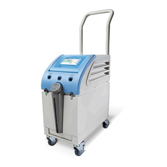
Front View Handle Power Loss Indicator Adjustable Control Panel Surface Sensor Core Sensor Socket Socket Water-out Water-In Quick Coupling Quick Coupling Connector Connector Water-Tank Water Level Indicator Figure 2: Front View DDT-063-000 Rev C Belmont Medical Technologies Page 16 of 106... -
Page 17: Figure 3: Side View
Allon User Manual ® Side View Figure 3: Side View DDT-063-000 Rev C Belmont Medical Technologies Page 17 of 106... -
Page 18: Figure 4: Rear View
Allon User Manual ® Rear Panel Figure 4: Rear View DDT-063-000 Rev C Belmont Medical Technologies Page 18 of 106... - Page 19 CAUTION!! The wraps are designed for single patient use only. Reusing may cause cross contamination and/or irritation. DDT-063-000 Rev C Belmont Medical Technologies Page 19 of 106...
- Page 20 • Patient side: Non-Woven Polypropylene • Exterior: Brushed Loop Fabric Usage Duration The wrap is durable for up to 28 hours. It is recommended to replace the wrap if it becomes soiled. DDT-063-000 Rev C Belmont Medical Technologies Page 20 of 106...
-
Page 21: Figure 5: Cardiac Thermowrap
Allon User Manual ® Selected Wrap Design Belmont Medical Technologies offers disposable ThermoWraps ® in four different ThermoWrap® designs. Universal ThermoWrap ® is used for any Cardiac ThermoWrap ® is used for typical surgery other than open-heart surgery. open-heart surgery or for complete For available sizes, see Table 3. -
Page 22: Figure 9: Measurements
Choose the appropriate model and size according to the parameters listed above. If the patient's overall height or overall weight matches the maximum value of a specific model, use the next larger size. Figure 9: Measurements Page 22 of 106 DDT-063-000 Rev C Belmont Medical Technologies... -
Page 23: Table 3: Thermowrap® Sizes
ThermoWrap ® Universal 512-03136 12/Box 91-104cm 1.225/0.841 (Pediatric) 512-03131 12/Box 79-91cm 1.118/0.739 524-03125 24/Box 7-11 Kg 0.983/0.629 ThermoWrap ® 524-03121 24/Box 4-7 Kg 0.698/0.604 Infant 524-03118 24/Box 2.5-4 Kg 0.660/0.465 Page 23 of 106 DDT-063-000 Rev C Belmont Medical Technologies... -
Page 24: Accessories
There are three color-coded temperature probes: Core (gray), Surface (green), and Infant Core (gray). Both core and surface temperature probes must be plugged into the Allon® device. The core temperature probe must be inserted into the patient and the surface temperature probe must be attached to the patient for the device to function properly. - Page 25 2.1. Disposable Surface Temperature Probe The disposable surface temperature probe is attached to the reusable surface adapter (green). The adapter is plugged into the green surface socket at the front of the Allon device. The ® temperature probe is attached to the patient's skin and measures surface body temperature.
-
Page 26: Table 4: Disposable Sensors
± 0.1°C Medical Grade Thermistor temperature 014-00021 Surface Skin temperature ± 0.3°C ± 0.1°C Medical Grade Thermistor Core Infant 014-00005 Infant Inner body ± 0.3°C ± 0.1°C Medical Grade Thermistor temperature Page 26 of 106 DDT-063-000 Rev C Belmont Medical Technologies... - Page 27 YSI 400 Series temperature probes. The Temperature Splitter measures the patient’s temperature using a single sensor in the patient, and displays the temperature on both the Allon ® screen and an additional system, such as a monitor, eliminating the need to use two separate sensors.
-
Page 28: System Specifications
Allon User Manual ® Figure 11: Temperature Splitter System Specifications See the following page for system specifications. Page 28 of 106 DDT-063-000 Rev C Belmont Medical Technologies... -
Page 29: Specifications
Allon User Manual ® SPECIFICATIONS This chapter lists and describes the technical specifications for the Allon ® system and CliniLogger™ accessory. Allon Technical Specifications ® Allon ® , one of Belmont Medical Technologies’ patient temperature management solutions, is a servo-controlled, non-invasive thermal regulation system. Allon’s algorithm-driven heat pump supplies heated water through the ThermoWrap®... - Page 30 28 hours unless soiled Wrap Storage Storage Span 5 years Temperature Conditions 10°C to 27°C Humidity Conditions 10-90% Wrap Transport Temperature Conditions -20°C to 60°C Humidity Conditions 20-95% Page 30 of 106 DDT-063-000 Rev C Belmont Medical Technologies...
- Page 31 Allon User Manual ® CliniLogger ™ CliniLogger™ is an optional accessory to Allon®/ CritiCool® / CritiCool® MINI Thermoregulation Systems. It is used to collect the system parameters during the thermoregulation procedure. Hardware Connector DB9 connector for serial interfacing to Allon ®...
-
Page 32: Chapter 3: Installation
® shipment and should be operational upon delivery. The unit should be unpacked, installed and tested only by Belmont Medical Technologies’ authorized personnel. No attempt should be made by the purchaser to unpack or assemble the unit alone. - Page 33 Allon User Manual ® Unpacking Allon From the Box The box should never be opened from the top. Instead, follow the instructions shown here. Assembling the Handle 1. To assemble the handle: 1. Release the four thumb screws by hand.
-
Page 34: Figure 12: Handle Assembly
– Power Cable – User Manual – Quick Reference Guide – Accessories Kit for Allon – one of the following: o 200-00400 Adult Accessory Kit with Reusable Temperature Probes o 200-00410 Accessory Kit for Disposable Temperature Probes o 200-00420 Infant Accessory Kit with Reusable Temperature Probes... -
Page 35: Moving The Unit
When the unit is stationary, the brakes must be in the locked position. Release the brakes only when transporting the unit. Packing Allon for Shipment Please follow these instructions to properly prepare Allon for transport. Empty the water tank prior to packing Allon. Page 35 of 106... -
Page 36: Chapter 4: Operating Instructions
® 4: O HAPTER PERATING NSTRUCTIONS General This chapter contains: – A description of the controls, indicators, and connections for the Allon ® device. – Detailed operating instructions for the Allon system. ® Controls, Indicators and Connections Included in this section is a short description of the following: –... -
Page 37: Control Panel
NOT applicable for the USA market or other select markets. Control Panel The adjustable control panel is located at the top of the Allon® device. Once the Allon device is turned on, all operating functions are controlled through ®... -
Page 38: Getting Started
® table or the patient’s bed. Press the brake pedals and lock the wheels to secure the Allon® device. Remove the water tank feeder cover and pour in sterile water or 0.22µ filtered water until the maximum allowable level is reached. -
Page 39: Figure 14: Initial Self-Test Screen
NOTE: In case of overfilling, see Table 11. Connect the Allon® device to the power source. Power on the Allon® device, which will initiate the Self-Test. (See Turning on the System.) Turning on the System To turn on the system: 1. -
Page 40: Figure 15: Preheating Water
– Heating and Cooling Unit – Temperature of Water Inflow and Water Outflow Self-Test Messages If there is a failure during the self-test, a message appears, and the Allon ® does not proceed to operation mode. See Chapter 7 “Troubleshooting” for details. - Page 41 ThermoWrap , confirm that the tubes have not twisted ® or bent. Connect the water tubes to the wrap and to the Allon ® . The wrap will automatically fill up, provided the self-test has completed.
- Page 42 ® Until the patient’s core temperature probe has been NOTE: inserted into the patient and Allon reads a valid core temperature, the water temperature flowing into the wrap will have a set point temperature of 38.5°C. Automatic temperature adjustments as determined by the physician will not be made until the core temperature probe has been inserted into the patient.
-
Page 43: Main Screen
Allon User Manual ® For proper use of the Allon device, the core and surface NOTE: ® temperature probes must be inserted per the instructions found with the probes. The location of the surface temperature probe is a clinical decision. All temperature probes directly measure temperature. -
Page 44: Menu Options
Menu Options Touch the Menu icon and select from the following options: – Standby – Select Mode – Temp. Graph – Settings – Services Figure 17: Menu Options DDT-063-000 Rev C Belmont Medical Technologies Page 44 of 106... -
Page 45: Figure 18: Stand-By Mode
® Standby The Standby Mode is used to stop the water flow and the thermoregulation. Allon still monitors the patient temperature while in Standby mode. The Allon ® ® device circulates the water internally and maintains the water temperature at the appropriate level to be ready when returning to operational mode. -
Page 46: Figure 19: Mode Select
Mode Select Mode Select allows you to choose between Normothermia mode and Manual mode. Select the mode you want to use and touch OK to confirm. Figure 19: Mode Select DDT-063-000 Rev C Belmont Medical Technologies Page 46 of 106... -
Page 47: Figure 20: Select Set Point Temperature
0.1°C. Each bar scale provides a change of 1°C. The temperature can be adjusted from 30 to 40°C. 3. Touch OK to confirm the selected temperature. DDT-063-000 Rev C Belmont Medical Technologies Page 47 of 106... -
Page 48: Figure 21: "Out Of Normothermia" Message
ThermoWrap®. For example, if the core temperature is 36°C (96.8°F) and the set-point temperature is 37°C (98.6°F), raising the setpoint of the Allon® system further will not affect the water temperature. The Allon® device automatically operates at the optimal level to obtain the desired set-point temperature. -
Page 49: Figure 22: Manual Mode Screen
Use the Temp Graph icon or the menu panel, to enter the graphic display of the current or last session. The Allon displays the current case ® parameters. If the wrap or the Temperature Probe/Adapter Cable is not connected, the last case will display. -
Page 50: Figure 24: Temp Graph Mode
– The screen can show 1 hour, 6 hours, 12 hours or 24 hours of a procedure. Use the double arrows to select the time range The Surface Temperature graph can be displayed or hidden by touching the Surf key. DDT-063-000 Rev C Belmont Medical Technologies Page 50 of 106... - Page 51 4. Touch OK at any time to confirm selection and to return to the operational mode. The Settings screen is divided into three sections and enables the operator to configure various parameters. DDT-063-000 Rev C Belmont Medical Technologies Page 51 of 106...
-
Page 52: Figure 25: Settings Screen
“Water temperature too high” o “Water temperature too low” o “Core readout too low” o “Connect surface sensor” o “Connect core sensor” o “Check surface sensor” o “Check core sensor” DDT-063-000 Rev C Belmont Medical Technologies Page 52 of 106... -
Page 53: Figure 26: All Temp Sensors Alarm Off Indicator
– Start up mode: Select the default operational mode upon startup: o Normothermia – Normothermia mode (recommended) o Manual – Manual mode o Last Mode – Last operational mode that was in use DDT-063-000 Rev C Belmont Medical Technologies Page 53 of 106... -
Page 54: Figure 27: Adjustable Alarm Limits
Changing the alarm limits should occur only under order NOTE: of a physician. NOTE: Once the alarm limits are set, the limits remain fixed and will not return to defaults. DDT-063-000 Rev C Belmont Medical Technologies Page 54 of 106... -
Page 55: Figure 28: Set Date And Time
Allon User Manual ® Section 3: Set Date and Time This section allows you to adjust the date and the time of the system. Figure 28: Set Date and Time DDT-063-000 Rev C Belmont Medical Technologies Page 55 of 106... -
Page 56: Figure 29: Services Screen
– Technician – Self Cleaning Figure 29: Services Screen Empty This function allows for emptying the system of the remaining water, prior to storage of the Allon ® system. To empty the water tank: 1. Switch to Standby Mode (see “Standby”). -
Page 57: Figure 30: Empty Mode
6. Wait for all the water to drain from the system. If Stop is touched, the ESC icon appears NOTE: and the action is stopped. Click the icon to continue. Page 57 of 106 DDT-063-000 Rev C Belmont Medical Technologies... -
Page 58: Figure 32: Tank Is Empty
When the machine is turned on, the system performs a self-check to ensure the system safety and performance. Technician This is a feature for Belmont Medical Technologies certified technicians only. It is password-protected. Page 58 of 106 DDT-063-000 Rev C... - Page 59 Allon User Manual ® Self Cleaning This is a feature for Belmont Medical Technologies certified technicians only. It is password-protected. This feature performs a thermal disinfection of the water tank and internal tubing. The thermal disinfection of Allon ® is an integrated feature, which heats the circulating water of the system, thus allowing the heat to disinfect the internal water pathways of the system, including the water tank.
-
Page 60: Turning Off The System
If the patient is not transferred with the Allon ® system, proceed to Step 11. 7. Place the temperature probes beside the patient. 8. Upon arrival to the hospital room, reconnect the temperature probes to the Allon ® DDT-063-000 Rev C Belmont Medical Technologies Page 60 of 106... - Page 61 12. Dispose of the ThermoWrap® in accordance with hospital guidelines governing non- toxic plastic waste. 13. Disinfect the surface of the connecting tubes and the exterior of the Allon® device (see instructions in Chapter 6). 14. Dispose of disposable temperature probes in accordance with hospital procedures for medical waste.
-
Page 62: Chapter 5: Ordering Information
017-00250) and an Operator’s Manual. All equipment and accessories may be ordered directly from your local Belmont Medical Technologies representative. When ordering parts, specify the model number as listed in this chapter as well as the serial number of your Allon ® device. -
Page 63: Table 7: Allon® Accessory Kits
Allon User Manual ® Table 7: Allon ® Accessory Kits Sub Part No. Description Sub Quantity 200-00400 Adult Accessory Kit with Reusable Temperature Sensors 014-00020 Reusable Core Temperature Probe, Adult, Gray 014-00021 Reusable Surface Temperature Probe, Green 200-00109 Connecting Water Tubes, 2 by 2 Way... -
Page 64: Table 8: Accessories Individual Replacement
Disposable Surface Temperature Probe, RJ (20/pack) 014-00028 Adaptor Cable for Disposable Core Temperature Probe, Gray 014-00129 Adaptor Cable for Disposable Surface Temperature Probe, RJ, Green 017-00250 CliniLogger™ assembly (Optional) 200-01200 Temperature Splitter Kit (Optional) Page 64 of 106 DDT-063-000 Rev C Belmont Medical Technologies... -
Page 65: Chapter 6: Maintenance
® 6: M HAPTER AINTENANCE Introduction This chapter outlines the maintenance instructions for the Allon® system. Qualified hospital staff may perform routine maintenance unless otherwise specified. CAUTION!! The repair and servicing of the Allon® system should be performed only by Belmont Medical Technologies or authorized agents of Belmont Medical Technologies. -
Page 66: Cleaning And Disinfection
• Replace filter * technician • Preventive maintenance Cleaning and Disinfection The cleaning and disinfecting of the Allon includes both external and ® internal cleaning and disinfection. All instructions regarding the reusable temperature NOTE: probes are not relevant for US market or other select markets. -
Page 67: Routine Maintenance
(EPA registration number 56392-7) – Chlorinated bleach solution (5.25% sodium hypochlorite concentration) – Quaternary ammonium compounds (ammonium chloride as active ingredient) Recommended Materials for Water Purification – Sodium dichloroisocyanurate (NaDCC) Page 67 of 106 DDT-063-000 Rev C Belmont Medical Technologies... - Page 68 2. Operate the machine on Standby mode for 30 minutes. 3. Drain the water using the Male Connector for Draining Water Tank. NOTE: The emptying process is an integrated feature of the Allon®. Refer to the Emptying instruction: “Empty”. Page 68 of 106...
- Page 69 Do not apply physical pressure on the screen. 10. Store the machine in a cool and dry place. Reusable probes - Not applicable for US market or other select markets Page 69 of 106 DDT-063-000 Rev C Belmont Medical Technologies...
-
Page 70: Cleaning, Disinfecting And Sterilization Of The Reusable Temperature Probes
Allon User Manual ® Thermal Disinfection The Thermal Disinfection of the Allon ® is an integrated feature, which heats the circulating water of the system, thus allowing the heat to disinfect the water tank from contamination. The Thermal Disinfection is performed for every new manufactured system and at every Periodic Maintenance (see Chapter 4). -
Page 71: Filter Replacement
– Pressure Meter – Heating and Cooling Unit – Temperature of Water Inflow and Water Outflow Successful completion of the system check service indicates that the Allon® device is operational. If the Allon was out of use for a long time, performing a full NOTE: ®... -
Page 72: Figure 34: Selecting System Check
2. In the Services screen, select System Check then click OK to confirm. A message appears requesting you to confirm start of System Check. Figure 35: System Check in Progress Page 72 of 106 DDT-063-000 Rev C Belmont Medical Technologies... - Page 73 System Check takes about 10 minutes. When the process is complete, a message appears on the screen “ SYSTEM CHECK COMPLETED”. 4. Switch to the Operation screen. 5. Turn Allon ® OFF. Switch off the Power Loss Alarm Disable if desired. Page 73 of 106...
-
Page 74: Chapter 7: Troubleshooting
Table 10 lists some possible scenarios that do not appear on the message display, their potential cause, and recommended actions. Table 11 lists water tank overfilling troubleshooting. Table 12 provides a list of fault messages that appear on the Allon ® device screen. -
Page 75: Table 10: Allon® System (No Message) Troubleshooting Guide
WARNING!!! The repair and servicing of the Allon ® system should be performed only by Belmont Medical Technologies or authorized agents of Belmont Medical Technologies. Table 10: Allon System (No Message) Troubleshooting Guide ® Observation Possible Problem Action to be Taken The power switch of the Allon Allon®... -
Page 76: Table 11: Water Tank Overfilled- Draining The Water Tank
® 4. Select Empty mode in Services and click Start. 5. Allow the excess water to drain into a receptacle, pail or sink. 6. When the desired water level has been reached, turn OFF the Allon ® device. Figure 36: ThermoWrap® Connecting Tubes and Special Male Connector... - Page 77 Allon ® User Manual Table 12: Allon ® System Messages Troubleshooting Guide Action to be Message Cause of Problem Comments taken Add Water Water level is too low Refill water tank to The alarm can be muted for maximum 10 minutes.
- Page 78 Allon ® User Manual Table 12: Allon ® System Messages Troubleshooting Guide (Con’t) Action to be Message Cause of Problem Comments taken Connect Surface Sensor No surface Connect surface No audible alarm. temperature probe is temperature inserted in its socket.
- Page 79 Allon ® User Manual Table 12: Allon ® System Messages Troubleshooting Guide (Con’t) Action to be Message Cause of Problem Comments taken Check Surface Sensor Misplacement of Connect the If the Surface temperature surface temperature surface probe was incorrectly probe in socket...
-
Page 80: Table 12: Allon® System Messages Troubleshooting Guide
ON again. If the problem The available values persists, range from 36-42° in turn OFF the Allon ® increments of 0.5°C: and contact your 37°C, 38°C, 39°C, local service 40°C, 41°C, and 42°C. - Page 81 Allon ® User Manual Table 12: Allon ® System Messages Troubleshooting Guide (Con’t) Action to be Message Cause of Problem Comments taken Out of Normothermia Range No alarm This appears when the Touching the OK operator chooses Set button confirms...
-
Page 82: Chapter 8: Messages And Alarms
Sound Pressure of the Alarms is 67.5 dBA at a distance of 10 centimeters. Technical Messages and Alarms The following technical messages might appear: Table 13: Technical Messages and Alarms Message Message window Add Water Connect Water Tubes DDT-063-000 Rev C Belmont Medical Technologies Page 82 of 106... - Page 83 Check Core Sensor Check Surface Sensor Follow the instruction of the technical messages to solve the problem. For example, add water if necessary, or connect temperature probes if not connected. DDT-063-000 Rev C Belmont Medical Technologies Page 83 of 106...
-
Page 84: Clinical Messages And Alarms
It is possible to change the range of these alarms in the Settings screen. NOTE: The user can choose at which temp the "High Patient Temp" and "Low Patient Temp" alarms will be activated. DDT-063-000 Rev C Belmont Medical Technologies Page 84 of 106... -
Page 85: Safety Messages And Alarms
• WATER TEMP. TOO LOW • WATER TEMP. TOO HIGH If such a condition occurs, the user should consider shutting down the system and finding the cause of the problem. DDT-063-000 Rev C Belmont Medical Technologies Page 85 of 106... -
Page 86: Informative Messages
The message appears at the bottom of the Main Screen. Informative messages include: • Out of Normothermia Range: • Connect Surface Sensor: Constant alarms occur in the following states: – Halt condition – Select Mode screen DDT-063-000 Rev C Belmont Medical Technologies Page 86 of 106... - Page 87 The limits are subject to change according to user settings. NOTE: Entering the limits range disables the alarms immediately. A new alarm is generated again after an additional 30 seconds after the out of the limit value is measured. DDT-063-000 Rev C Belmont Medical Technologies Page 87 of 106...
-
Page 88: Chapter 9: Optional Clinilogger
NSTRUCTIONS Overview and Installation Introduction The purpose of the CliniLogger™ device is to save the Allon® / CritiCool® systems' vital data for further reference. By means of the CliniLogger™ Viewer software, the user can use an external PC to review this saved data. -
Page 89: Figure 37: Clinilogger™ Initialization
When initialization finishes the following screen appears. Figure 38: CliniLogger™ Installation 5. You can change the installation location by clicking Browse and selecting a new location. Click Next. The License Agreement window appears. DDT-063-000 Rev C Belmont Medical Technologies Page 89 of 106... -
Page 90: Figure 39: Clinilogger™ Agreement
Figure 39: CliniLogger™ Agreement 6. Select I accept the above 2 License Agreement(s) to accept the license agreements and click Next. The Start Installation window appears. Figure 40: Start Installation DDT-063-000 Rev C Belmont Medical Technologies Page 90 of 106... -
Page 91: Figure 41: Installation Progress
7. Click Next; you can follow the installation progress in the progress bars until it finishes. Figure 41: Installation Progress When the installation is finished, the Installation Complete window appears. Figure 42: Installation Complete DDT-063-000 Rev C Belmont Medical Technologies Page 91 of 106... -
Page 92: Using The Clinilogger™ Viewer Application
Verify that the CliniLogger™ device is connected NOTE: to the COM 1 –10 port or you can use with USB to RS232 adaptor. 4. Click Connect to Logger, the software traces the COM port DDT-063-000 Rev C Belmont Medical Technologies Page 92 of 106... -
Page 93: Figure 44: Clinilogger™ Window
CliniLogger™ continues to burn data from the last patient. Viewing Downloaded Data 1. To view downloaded data: 1. Double-click the CliniLogger™ Viewer icon. The CliniLogger™ window appears. Figure 44: CliniLogger™ Window DDT-063-000 Rev C Belmont Medical Technologies Page 93 of 106... -
Page 94: Figure 45: Clinilogger™ Window
Figure 45: CliniLogger™ Window 2. Click Load stored data and choose the file you would like to view. When the data has been loaded the message appears Figure 46: “Complete” Message DDT-063-000 Rev C Belmont Medical Technologies Page 94 of 106... -
Page 95: Figure 47: Clinilogger™ Viewing Panel
Figure 47: CliniLogger™ Viewing Panel The CliniLogger™ viewing panel includes the following data: – Start date and time received from the thermoregulation device (Allon® / CritiCool ® ) – Software version of the thermoregulation device – Close Window button – Function Selection Area: Control keys –... -
Page 96: Figure 48: Graphics Display Area
– Temperatures Graphs: Set-point, Core and Surface as a function of time – Modes and Error Area: Thermoregulation modes, Rewarming step and errors as a function of time – Device Functional Status Area: Heat/Cool and Pump On/Off DDT-063-000 Rev C Belmont Medical Technologies Page 96 of 106... -
Page 97: Figure 49: Function Selection Area
Temperature Settings Wrap Settings Errors/TempStep Settings Figure 50: Example Modes and Errors Area Temperature graph control buttons enable modifying the display of each of the temperature graphs. DDT-063-000 Rev C Belmont Medical Technologies Page 97 of 106... -
Page 98: Table 15: Zoom Tool Buttons
Click this zoom tool button. Using the mouse move the cursor and Y directions to the Temperature graph; the cursor image changes to the button icon. Click the mouse to zoom out. You can click again to zoom out again. DDT-063-000 Rev C Belmont Medical Technologies Page 98 of 106... - Page 99 1. To set the time of the cursor: 1. Use the keyboard to set the required time in the Cursor textbox. Make sure to select the time as displayed on the graph (and in the DDT-063-000 Rev C Belmont Medical Technologies Page 99 of 106...
-
Page 100: Table 16: Mode Codes
(yellow markings). Figure 52: Example of “Modes and Error Area” Table 16: Mode Codes Code Indicates PowerUp Cooling Adult PowerUp Cooling Neonate PowerUp Warming Adult PowerUp Warming Neonate PowerUp Rewarm Adult DDT-063-000 Rev C Belmont Medical Technologies Page 100 of 106... - Page 101 When the device is warming the water in the tank- the line is red. – Pump On/Off- When the pump is pumping water into the Wrap- the line is green. When Allon ® is circulating the water internally (i.e.
- Page 102 A second page in the Excel file shows a graphic description of the Excel table with the Y axis showing the temperatures, and the X axis the Excel table lines. DDT-063-000 Rev C Belmont Medical Technologies Page 102 of 106...
-
Page 103: Figure 53: Selection Of Graph Chart
‘Installing the Software’ section for more information on this process. Installation Procedure: • Copy the folder “900-00350 CliniLogger Viewer Software_Tech v1.6.3” from the CD to a location on the desired PC. • Run the CliniLogger tech.exe application. DDT-063-000 Rev C Belmont Medical Technologies Page 103 of 106... -
Page 104: Appendix A: Customer Service
ERVICE Belmont Medical Technologies USTOMER ERVICE EPRESENTATIVE WARNING!!! The following details are necessary to contact your Belmont Medical Technologies representative. Keep this form with the User’s Manual for easy access for scheduling annual periodic maintenance and/or for servicing needs. Representative... -
Page 105: Appendix B: Rf Separation
The Allon ® and CliniLogger™ are intended for use in an electromagnetic environment in which radiated RF disturbances are controlled. The customer or the user of the Allon ® and CliniLogger™ can help prevent electromagnetic interference by maintaining a minimum distance... -
Page 106: Appendix C: Declarations Of Compliance
Guidance and Manufacturer’s Declaration – Electromagnetic Emissions The Allon ® device is intended for use in the electromagnetic environment specified below. The customer or the user of the Allon ® device should assure that it is used in such an environment. Emissions test Compliance Electromagnetic Environment –...
Need help?
Do you have a question about the Allon and is the answer not in the manual?
Questions and answers