
Related Manuals for Belmont FMS2000


Summary of Contents for Belmont FMS2000
- Page 1 SERVICE MANUAL ® FMS2000 The Belmont Rapid Infuser 780 Boston Road Billerica, MA 01821, USA 866-663-0212 US/Canada 978-663-0212 Worldwide...
- Page 2 ® The Belmont Rapid Infuser, FMS2000 SERVICE MANUAL Belmont Instrument LLC 780 Boston Road Billerica, Ma 01821, USA Wellkang Tech Consulting Suite B, 29 Harley Street London, W1G 9QR England, United Kingdom Tel: +44 (20) 32876300 Fax: +44 (20) 76811874 All service calls &...
-
Page 3: Table Of Contents
Table of Content Chapter 1: Introduction & Overview Introduction ....................... 1-1 ® Overview of the Belmont FMS2000 ..............1-2 Fluid Pump....................1-4 Heating System and Temperature Monitoring ..........1-4 Pressure Monitoring ..................1-4 Air Detectors ....................1-5 Diversion Valve ................... 1-5 Alarm and Alarm Messages ................ - Page 4 Table of Content Fluid Infusion, Continuous ................3-30 Automatic Warming ................... 3-30 Pressure Control ..................3-30 Automatic Air Purging ................3-31 Bolus Infusion, Infuse a Fixed Volume ............3-31 Recirculation Mode ..................3-31 Protection from Accidental Power Off ............. 3-32 End of Procedure ....................
- Page 5 Table of Content 5. Miscellaneous Modules ............... 4-45 • Heater Component ..............4-45 • Membrane Panel switch (Touch Screen) ........4-45 • Roller Pump ................4-45 • Diversion Valve ................4-46 • Temperature Probe Assembly ............ 4-46 • Circuit Breaker................4-46 •...
- Page 6 Table of Content Chapter 6: Settings System Parameters and System Calibration System Parameters Setup ................6-72 Date/Time ..................6-74 • Alarm Volume ................6-75 • Display Brightness ................. 6-75 • Key Rate ..................6-75 • Bolus Volume ................6-75 • Pressure Limit ................
- Page 7 Table of Content 4. Electrical Safety Test - Leakage Current ........7-90 a. Earth leakage Current ..........7-90 b. Patient Leakage Current ..........7-91 5. Hardware Verification .............. 7-92 a. Valve ................7-94 b. Fluid Out and Air Detectors .......... 7-94 c.
- Page 8 Table of Content Heating Alarms………………………………………………………. 8-116 Heating Fault………………………………………………… 8-116 • Over Temperature………………………………………….. 8-116 • Hardware Alarms…………………………………………..…………8-117 Air Detector Fault……………………………………………..8-117 • Heater Fault Latch…………………………………………… 8-117 • Heater Power Read Back Fault…………………………... 8-117 • Heater Over Power Fault………………………………….. 8-117 • Power Module Overtemp………………………………….. 8-118 •...
-
Page 9: Introduction
1. Introduction - Overview INTRODUCTION The BELMONT FLUID MANAGEMENT SYSTEM, FMS2000 infuses blood, replacement IV fluids or irrigation fluids warmed to physiologic temperature at user-set rates from 10 to 750 milliliters per minute (ml/min) with 1000 ml/min option. Low infusion rates of 2.5 and 5.0ml/min (150 and 300ml/hr) are also available to keep the venous line open. -
Page 10: Overview Of The Belmont Fms2000
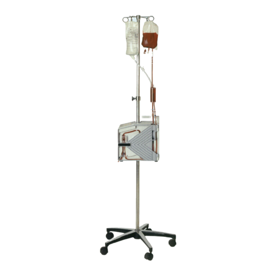
1. Introduction - Overview OVERVIEW OF THE BELMONT FMS2000 The complete system consists of the FMS2000 Control System, which is mounted on an IV pole, and the FMS2000 System Disposable Set. The Control System consists of three major components: A high speed fluid pump. - Page 11 1. Introduction - Overview Pump Head Tubing Heat Exchanger Display Pressure Fluid Out Detector Transducer (Behind Pump Head Tubing) (Behind Pressure Chamber) Power Pressure Switch Chamber In-Line Air Detector Output Infrared Fluid Pump Temperature Probe (Inside case) Valve Input Infrared Temperature Probe (Inside case) System Diagram Showing Main Components...
-
Page 12: Fluid Pump
1. Introduction - Overview FLUID PUMP The roller type peristaltic fluid pump is designed to obtain low hemolysis, consume low power, is lightweight and very reliable. The pump speed is controlled by the demanded flow rate that is set by the operator. The pump head can be removed for cleaning. The pump is mounted near the top of the Control System just below the “Fluid Out"... -
Page 13: Air Detectors
1. Introduction - Overview AIR DETECTORS Air in the system is vented through a hydrophobic filter at the top of the Reservoir Chamber in the Disposable. During infusion, after every 500 ml infused, the system will automatically recirculate any air in main fluid circuit back into the Reservoir Chamber to be vented. -
Page 14: Control Panel: Display And Keys
1. Introduction - Overview CONTROL PANEL: DISPLAY AND KEYS The control panel consists of the touch screen display, which incorporates a bright graphical display with touch pad keys. The display shows status and alarm messages at the top and middle, and contains the touch keys at the bottom. CONTROL PANEL SUMMARY Status Display: Flow Rate in ml/min... -
Page 15: Chapter 2: Technical Specifications
2. Technical Specifications Technical Specifications of the Belmont FMS2000 DIMENSION Size 13.5" x 12" x 7.5" (34.29cm x 30.48cm x 19.05cm) Weight 28 lbs (12.7 Kg) PORTABILITY Hand Carry Handle on top of unit for easy transport I.V Pole Mount I.V pole mountable or free standing. -
Page 16: Environment
2. Technical Specifications ENVIRONMENTAL Operating Temperature 10ºC to 32ºC (50ºF to 90ºF) Storage Temperature -15ºC to 40ºC Relative Humidity 10% to 90% Pressure 49 to103 kPa Shock and Vibration Meet MIL STD.810E method 514.4 (Basic Transportation) Electromagnetic Meet EN60601-1-2 (2007) and IEC 60601-1-2 (2007) Compliance OPERATING PARAMETERS... -
Page 17: Operating Panel
2. Technical Specifications OPERATING PANEL Control Panel and Display Splash proof touch screen display Display Area 5" X 2.5" (12.7cm X 6.35cm) Status Display Flow rate (ml/min) Total volume infused (ml) Line pressure (mmHg) Output infusate temperature (ºC) Bolus volume (ml) Alarm messages Keys are displayed appropriate to the particular point Functional Keys... -
Page 18: Alarm States And Controls
2. Technical Specifications ALARM STATES and ALARM MESSAGES CONTROLS Operator Setting, User- MISSING DISPOSABLE correctable DOOR OPEN FLUID OUT AIR DETECTION HIGH PRESSURE System Status LOW BATTERY System Failures AIR DETECTOR FAULT PUMP FAULT VALVE FAULT HEATER FAULT LATCH HEAT POWER READ BACK FAULT HEATER OVER POWER FAULT POWER MODULE OVERTEMP HEATING FAULT... -
Page 19: Symbols And Definitions
2. Technical Specifications SYMBOLS AND DEFINITIONS Symbol Description Compliance to Medical Device Directive 93/42/EEC Alternating current Equipotentiality Standby Caution Consult accompanying documents/refer to manual Defibrillator-proof type CF equipment Protected against dripping water IPX2 Serial Number Manufactured by Authorized European Representative 2-11... -
Page 20: Chapter 3: Operation & System Set-Up
3. Operation & System Set-up STEP-BY-STEP SUMMARY OF OPERATING PROCEDURES The following is a step-by-step summary of the major steps for proper operating the FMS2000; the remainder of the chapter explains each step in detail. Inspect the system SET-UP Power cord: use only supplied power cord •... - Page 21 Mount the FMS2000 on a 5-wheel IV pole with a maximum pole diameter of 1 inches (3.18 centimeters) and a minimum base diameter of 24 inches (61 centimeters) capable of supporting the weight of the machine, 26 lbs (11.8 kilograms) and fluids.
- Page 22 CLAMP PLASTIC WASHER IV mounting of the FMS2000 with support assembly (Clamp and Washer) Make certain that there is nothing obstructing the air vents at the bottom of the system. Do not operate the system while it is lying on its side.
-
Page 23: Installing The Disposable Set
3. Operation & System Set-up INSTALLING THE DISPOSABLE SET 3- Spike disposable set with key components Clamps Bag Spike Vent Caps Spikes Vent Reservoir Chamber Coarse Filter Check Valve Red Tinted Tubing Heat Fluid Out Exchanger Detector Interlock Pressure Block Chamber Pump Head Detector... - Page 24 CAUTION: Do not alter or change any part of the disposable set, which is specifically designed for use in the FMS2000. Any changes or alterations may endanger the patient or damage the system. WARNING! To avoid risk of electric shock, this device must only be connected to supply mains with protective earth.
- Page 25 3. Operation & System Set-up CAUTION: Immediately wipe any spills from device Tubing path in the system Remove the disposable set from the tray and lay the reservoir chamber over the top of the machine. Open the door. Insert the heat exchanger with the red arrow pointing up.
- Page 26 3. Operation & System Set-up Place the thinner recirculate line to the right of the air detector, and to the right of the valve wand. Pressure Transducer Detector Insert infuse line here. Insert Valve recirculate Wand line here. WARNING! Do not apply excessive pressure to the pressure chamber or pressure transducer.
-
Page 27: Installing The 3.0 Liter Reservoir
3. Operation & System Set-up INSTALLING THE 3.0 LITER RESERVOIR Disconnect Standard Fluid Supply Connect 3.0 L Reservoir to the 3- Spike Disposable Set Using aseptic techniques, remove the standard fluid supply from the 3-spike disposable set by disconnecting the luer connectors. Completely clamp off the larger pump tubing. - Page 28 Make certain the two connection leads underneath the reservoir are not stretched or kinked. Stretched or kinked connection leads can cause flow restrictions and frequent Fluid Out alarms. Install the 3-spike disposable set into the FMS2000, as previously shown. CAUTION: Do not pressurize or apply a vacuum to the reservoir.
-
Page 29: Powering On The System
3. Operation & System Set-up POWERING ON THE SYSTEM Check that the detachable power cable is securely seated in the main power receptacle. Plug the system power cord into an appropriate AC receptacle. Do not use an adaptor for ungrounded outlets. Turn power on by switching the circuit breaker to the ON position. -
Page 30: Priming The Disposable Set
3. Operation & System Set-up PRIMING THE DISPOSABLE SET Figure 2. Prime screen 1 We strongly recommend loading and priming the disposable set just prior to the procedure The system is primed in two steps using solution compatible with blood. DO NOT USE CALCIUM-CONTAINING SOLUTIONS: Prime the Main System. - Page 31 3. Operation & System Set-up CAUTION: Bag port filters may impede flow of viscous fluids. They can clog or trap air, which can block flow. Use high quality infusate. High amounts of particulates in the blood may clog the bag filter and/or coarse blood filter inside the reservoir chamber.
- Page 32 3. Operation & System Set-up If air is detected during Prime, the volume countdown will be reset to 100 ml again. Air in the disposable set is recirculated back to the reservoir chamber and vented out the hydrophobic filter located on top of the reservoir chamber or back into the fluid bags if both bag spikes have pierced the fluid bag(s) and both bag clamps are opened.
-
Page 33: Priming The Patient Line
3. Operation & System Set-up PRIMING THE PATIENT LINE The patient line must be primed before infusion. The user controls both the speed and duration of the Patient Line Prime. This step primes the patient line with warm fluid. Press PT. LINE PRIME once to prime at 50 ml/min or press and hold the key to prime at 200 ml/min. -
Page 34: Connect To Patient
3. Operation & System Set-up CONNECT TO PATIENT WARNING! Before continuing, the operator must inspect and make certain that the patient line is completely primed and free of air. Any air bubbles after the diversion valve in the patient line must be removed before the procedure can be safely continued. - Page 35 3. Operation & System Set-up WHEN PT. LINE PRIMED PRESS STOP AND THEN INFUSE STOP PT LINE INFUSE PRIME Figure 6. Patient Line Prime CONTROLS PATIENT LINE Primes the patient line with warm fluid. Press the key once to PRIME prime at 50 ml/min or press and hold the key to prime at 200 ml/min.
-
Page 36: Main Operating Screen
500 ml/min RATE Set the system to the rate of 500 ml/min. The FMS2000 will pump the volume indicated on the BOLUS BOLUS key at a rate of 200 ml/min. The bolus volume on the key can be set in the Service mode (see Chapter 6) or by pressing and holding down the BOLUS key while in the Infuse screen. - Page 37 3. Operation & System Set-up RECIRC Sets the system into the Recirculation mode to remove air in the line and to preheat the reservoir chamber and disposable set. The valve shuts off the infuse line to the patient and sends the fluid to recirculate through the system at a preset rate of 200 ml/min.
-
Page 38: Fluid Infusion, Continuous
3. Operation & System Set-up FLUID INFUSION, CONTINUOUS The infuse rate automatically starts at 10 ml/min when the main operating screen first appears. Adjust the flow rate by pressing INFUSE RATE INFUSE RATE ress 500 ml/min RATE to immediately set the infuse rate to the 500 ml/min. Automatic Warming •... -
Page 39: Automatic Air Purging
3. Operation & System Set-up Automatic Air Purging • After every 500 ml of fluid infused, the diversion valve will momentary switch into the recirculate position for a short duration to automatically remove air from the main system fluid circuit into the reservoir chamber. Air in the reservoir chamber may be vented out the hydrophobic filter or back into the fluid bag if bag spikes attached to fluid bags are opened. -
Page 40: Protection From Accidental Power Off
3. Operation & System Set-up PROTECTION FROM ACCIDENTAL POWER OFF Figure 8. Circuit breaker was turned to STANDBY while pumping. If the circuit breaker was turned to the STANDBY position while the system is pumping, the system will stop pumping, alarm and display, Figure 8. This message is to protect the system from being accidentally powered down during a procedure. -
Page 41: Battery Operation
3. Operation & System Set-up BATTERY OPERATION Figure 9. Infuse screen while in battery operation. The system can operate in battery mode during transport. The built-in rechargeable battery automatically charges whenever the system is connected to line power. system automatically switches to battery operation when the AC line is disconnected. Battery operation should be used only briefly or at very low flow rates because there is no heating. -
Page 42: Restarting The System
3. Operation & System Set-up RESTARTING THE SYSTEM If the system ever needs to be restarted from power off after the initial startup, • follow the same procedure and precautions as the initial startup to restart the system. The Main System Prime and Patient Line Prime cannot be bypassed. The volume accounting information on the VOL status line in the Main Infuse •... -
Page 43: Chapter 4: Theory Of Operation
See drawing 705-00022. Theory of Operation The FMS2000 system consists of four (4) main modules: power module, daughter board, computer board, and AC/DC board. In addition to these main modules, there are a membrane panel switch for user interface, roller pump, diversion valve, two (2) temperature probe assemblies, circuit breaker, and a power entry module. -
Page 44: Emi Filter Board
EMI Filter Board: The EMI filter board provides the necessary filtering for conducted emissions both into and out of the FMS2000. Both common mode and single ended filtering are employed. The board also contains transient protection. AC power enters the system through the EMI board where it is filtered. -
Page 45: Heatsink Assembly
4. Theory of Operation This voltage is applied to a voltage-to-frequency converter, which produces a frequency that is proportional to the output power. A counter then generates a number that is used by the system computer to control the output power under software control, thus closing the control loop. The counter is continuously monitored in hardware for a number that exceeds the maximum power level. -
Page 46: Daughter Board
4. Theory of Operation Daughter Board +30VDC TO SYSTEM ON/OFF ON/OFF CONTROL FROM AC/DC SWITCH TO CPU BD SUPPLY BOARD BATTERY BATTERY CHARGER +80VDC DC/DC +5VDC EMI FILTER -100VDC SUPPLY -105VDC REFERENCE VOLTAGE PUMP MOTOR PUMP MOTOR DRIVER PRESSURE PRESS. SENSOR AMP. -
Page 47: Computer Board
4. Theory of Operation The daughter board contains: battery control circuitry, DC/DC power supply, roller pump motor driver, valve motor driver, valve position sensors, pressure transducer and amplifier, RS232 port, air detector electronics, sound transducer, and door position sensor. The temperature probe assemblies, which are mounted on the support housing, are connected to the daughter board by cables. - Page 48 4. Theory of Operation An RS232 port driver changes the serial data logic level signals to RS232 levels. A ribbon cable carries data to a DB9 connector on the support housing. The RS232 port is used in factory troubleshooting only. The air detector electronics (OEM circuit boards) are mounted directly to the daughter board.
- Page 49 4. Theory of Operation Computer Board Computer Board Diagram ON/OFF 5V REF DATA ACCESS SWITCH CONTROL BATTERY INPUT THERMOPILE VOLTAGE OUTPUT , RAM, THERMOPILE WATCHDOG VOLTAGE INPUT AMBIENT TEMPERATURE DISPLAY DISPLAY CONTROL MEMORY SYSTEM OUTPUT AMBIENT TEMPERATURE ON/OFF SWITCH 10 BIT PUMP MOTOR PUMP MOTOR CONTROL...
-
Page 50: The Cpu
4. Theory of Operation The computer board contains a CPU, memory, system software stored in EPROM, and two (2) Field Programmable Gate Arrays (FPGA’s) containing logic for display control, 8 channel 10 bit ADC, valve control, pump motor control, keyboard scan, fault monitoring, watchdog, and serial interface. - Page 51 4. Theory of Operation The motor FPGA performs various functions. The main function is to control the speed of the motor and to decode the encoder signals from the back of the motor. It also scans the keyboard, provides valve control, tests the air detectors and watchdog functions.
-
Page 52: Ac/Dc Power Supply Board
4. Theory of Operation AC/DC Power Supply Board BRIDGE FLYBACK REGULATOR RECTIFIER TRANSFORMER FUSE AC FROM EMI BOARD FILTER 30VDC ISOLATED The AC/DC power supply board converts 85 to 260 volts AC, at 50 to 400 Hz, to 30 volts isolated DC. The supply contains its own EMI filter and provides a regulated output. - Page 53 4. Theory of Operation Miscellaneous Modules The support housing holds all the components/modules. The left side cover holds two (2) 12 volt sealed lead acid batteries and the pole clamp mechanism. The door holds one of the heater assembly ferrite pole pieces. Some of the components are listed below: The heater components: ferrite pole pieces, bobbin, heater winding and heater...
- Page 54 The power entry module is a 16 A, 250 V, capable of withstanding a 2000 VAC dielectric strength for 1 minute. The AC line power enters the FMS2000 via a removable power cord, which plugs into this connector.
- Page 55 REMOVAL AND REPLACEMENT OF MAJOR COMPONENTS AND MODULES Before beginning any Removal and Replacement procedure(s): • o FMS2000 Circuit Breaker should be switched OFF and unplug the unit from the wall outlet After any Removal and Replacement certain components or module(s), FMS •...
- Page 56 5. Removal and Replacement of Major Components and Modules INSTRUMENT COVER (Reference Drawing: 403-00108) Removal Lay the unit with the door face down. Using an Exacto knife or flat razor blade, cut through the silicone around the perimeter of the instrument cover. Remove the “Warranty Void”...
- Page 57 5. Removal and Replacement of Major Components and Modules ACTUATOR HANDLE (Reference Drawing: 403-00108) Removal Remove 1, 8-32 x 3/4 button head hex screw, lock washer and flat washer attaching Actuator Handle to Shaft Coupling. Slide Actuator Handle off Actuator Shaft Coupling. (Do not remove 2X Disk Springs.
-
Page 58: Air Detector Transducer
5. Removal and Replacement of Major Components and Modules AIR DETECTOR SENSOR (Reference Drawing 403-00107) (For Air detector sensor, P/N 310-00024) Removal Refer to Step K Removal, to remove the Daughter PCB, Using an Exacto knife, remove the silicone from the detector. Remove the two screws and the spacer from the air detector. -
Page 59: C152 Replacement
5. Removal and Replacement of Major Components and Modules C152 REPLACEMENT (Reference Drawing: 403-00107) Removal Refer to Step A Removal, 1 – 7, to remove the instrument cover. Ground strap must be worn. Remove CPU PCB. (See Step J.) Locate C152 position. Use a solder pull or solder wick to remove left over solder. -
Page 60: Ceramic Disk
5. Removal and Replacement of Major Components and Modules CERAMIC DISK (DISH HEATER) (Reference Drawing 403-00109) Removal Remove Door Assembly from Support Housing, by pulling upward. Place a protective covering over Cover and lay Door Assembly face down on a flat surface. Cut through silicone around Ceramic Disk. -
Page 61: Circuit Breaker
5. Removal and Replacement of Major Components and Modules CIRCUIT BREAKER (Reference Drawing: 403-00107 (for 120V unit) or 403-00270 (for 230V unit) Removal Remove 4 X 6-32 pan head Phillips screws [(2) ¼” & (2) 1 1/8”] connecting Circuit Breaker to Support Housing. Refer to Step A Removal, 1 –... -
Page 62: Cpu Pcb & Display
5. Removal and Replacement of Major Components and Modules CPU PCB & DISPLAY (Reference Drawing: 403-00107) Removal Ground strap must be worn. Remove the instrument cover. (See Step A Removal, 1 – 7.) Unplug Membrane Panel Cable from CPU PCB. Unplug CPU PCB Cable from Daughter PCB. -
Page 63: Daughter Pcb
5. Removal and Replacement of Major Components and Modules DAUGHTER PCB (Reference Drawing: 403-00107) Removal Ground strap must be worn. Remove the instrument cover (See Step A Removal, 1 - 7) Remove AC/DC PCB. (See Step B.) Remove Pump Motor. (See Step X.) Unplug all cables connected to Daughter PCB. - Page 64 5. Removal and Replacement of Major Components and Modules DAUGHTER PCB (continued) PUMP MOTOR FLUID OUT DETECTOR ELECTRONIC, NOT USED, IF USES 310-00023 NYLON WASHER OUPUT TEMP PROBE INSTRUMENT COVER Figure 5: Daughter PCB 5-56...
-
Page 65: Heater Control Pcb
5. Removal and Replacement of Major Components and Modules DRIVER PCB “A”, DRIVER PCB “B”, & HEATER CONTROL PCB (Reference Drawing: 403-00132) Removal Ground strap must be worn. Remove Power Driver Module. (See Step V.) Remove 8X pan head Phillips screws from back of EMI Filter PCB. - Page 66 5. Removal and Replacement of Major Components and Modules DRIVER PCB “A”, DRIVER PCB “B”, & HEATER CONTROL PCB (continued) TRANSISTOR MOUNTING CLAMPS Figure 6: Driver ‘A’, ‘B’, and Heater Control PCB 5-58...
-
Page 67: Emi Filter Pcb
5. Removal and Replacement of Major Components and Modules EMI FILTER PCB (Reference Drawing: 403-00132) Removal Ground strap must be worn. Remove Power Driver Module. (See Step V.) Unplug EMI Cable from EMI Filter PCB, JP4. Remove 8X pan head Phillips screws from EMI Filter PCB. Remove EMI Filter PCB and store in a static proof bag. -
Page 68: Fan Guard
5. Removal and Replacement of Major Components and Modules FAN GUARD (Reference Drawing: 403-00107) Removal Lay unit on its side. Remove 8, 6-32 x 3/8 flat head Phillips screws attaching Fan Guards to Support Housing. Remove Fan Guards. Installation Reinstall Fan Guards and screws. FLUID OUT DETECTOR PCB (Reference Drawing: 403-00107) (If P/N 310-00023 is used, Fluid Out detector PCB is not needed) - Page 69 5. Removal and Replacement of Major Components and Modules FLUID DETECTOR SENSOR (Reference Drawing: 403-00107) (For Fluid Out detector sensor, P/N 310-00023) Removal Refer to Step B Removal, to remove the AC/DC PCB. Refer to Step I Removal, to remove the circuit breaker. Disconnect the two connectors labeled JP4, JP5 from the Daughter PCB.
-
Page 70: Iec Connector (Power Entry Module)
5. Removal and Replacement of Major Components and Modules IEC CONNECTOR (Power Entry Module) (Reference Drawing: 403-00107 for 120V unit) or 403-00248 (for 230V unit) Removal Unplug AC Input Cable. Remove Power Driver Module. (See Step V.) Remove AC Ground Cable. Remove (2) lugs, from JP2 and JP5, on the EMI board Remove IEC Connector by pinching the top and bottom of connector and sliding it out of the Support Housing. -
Page 71: Input Temperature Probe
5. Removal and Replacement of Major Components and Modules INPUT TEMPERATURE PROBE (Reference Drawing: 403-00107) Removal Remove the Instrument Cover. (See Step A Removal, 1 – 7.) Unplug Input Temperature Probe Cable, JP15, from Daughter PCB. Remove 2X pan head Phillips screws attaching Input Temperature Probe to Support Housing. -
Page 72: Membrane Panel
5. Removal and Replacement of Major Components and Modules MEMBRANE PANEL (Reference Drawing: 403-00107) Removal Remove the instrument cover. (See Step A Removal, 1 – 7.) Remove 1X pan head Phillips screw & 1X flat washer attaching Membrane Panel Ground Strap to Support Housing. Remove tape from Membrane Panel Ground Strap. -
Page 73: Output Temperature Probe
5. Removal and Replacement of Major Components and Modules OUTPUT TEMPERATURE PROBE (Reference Drawing: 403-00107) Removal Remove Pump Motor. (See Step V.) Unplug Output Temperature Probe Cable, JP8, from Daughter PCB. Use an Exacto knife to cut through the silicone on the front of the temperature probe. -
Page 74: Power Driver Module
5. Removal and Replacement of Major Components and Modules POWER DRIVER MODULE (Reference Drawing: 403-00132) Removal Refer to Step A Removal, 1 – 7, to remove the Instrument Cover. Ground strap must be worn before removing the Power Driver Module. Remove 4X flat head Phillips screws and Fan Guard attaching fan to Support Housing. - Page 75 5. Removal and Replacement of Major Components and Modules POWER DRIVER MODULE (continued) 2X CONNECTS TO AC/DC PCB CAPACITOR BLOCK CONNECTS TO BOBBIN ASSEMBLY CONNECTS TO IEC CONNECTOR CONNECTS TO DAUGHTER BOARD PCB CONNECTS TO IEC CONNECTOR Figure 8: Power Module Assembly 5-67...
-
Page 76: Pressure Transducer
5. Removal and Replacement of Major Components and Modules PRESSURE TRANSDUCER (Reference Drawing: 402-00034A) Removal Ground strap must be worn. Remove AC/DC PCB. (See Step B.) Remove Pump Motor. (See Step X.) Remove Daughter PCB. (See Step K.) Cut Pressure Transducer legs off from Daughter PCB. Use hot soldering iron, remove remaining legs from Daughter PCB. -
Page 77: Pump Motor
5. Removal and Replacement of Major Components and Modules PUMP MOTOR (Reference Drawing: 403-00107) Removal Refer to Step A Removal, 1 – 7, to remove the Instrument Cover. Unplug Maxon Cables, JP 9 (Ribbon cable) and JP1 (red & black cable) from the Daughter PCB. -
Page 78: Valve Motor And Pincher
5. Removal and Replacement of Major Components and Modules VALVE MOTOR/PINCHER (Reference Drawing: 403-00107) Removal Refer to Step A Removal, 1 – 7, to remove the instrument cover. Unplug cable, JP14, connecting to Daughter PCB. Remove 1X set screw from Valve Pincher. Remove Valve Pincher. - Page 79 5. Removal and Replacement of Major Components and Modules Drawing Number Description 402-00034A Assembly, Daughter PCB (750 ml/min max. rate) 403-00107 Assembly, Final, 120 V unit (750 ml/min max. rate) 403-00343 Assembly, Final, 120 V unit (1000 ml/min max. rate) 403-00108 Assembly, Instrument Cover 403-00109...
-
Page 80: System Parameters Setup
6. Setting System Parameters and Systems Calibration SYSTEM PARAMETERS SETUP Listed below are System Parameters Setup and Hardware Calibration. These calibrations, pressure transducer, temperature probes, and power module, need to be calibrated only after verifying that it is operating outside accepted parameters. See Hardware Verification, Chapter 7. -
Page 81: Date/Time
Parameter Setup is performed in the Service mode. SERVICE mode screen Pressing the SERVICE key accesses the Calibration/Set-up mode. This key appears on the BELMONT logo screen only at system powered-up. This screen remains active for 4.5 seconds before the system enters the Prime mode. CALIBRATION/SET-UP... - Page 82 6. Setting System Parameters and Systems Calibration Date/Time Press DATE TIME in the CALIBRATION/SET-UP screen to set the time and date. Press either the TIME or DATE key. Screen after pressing DATE TIME key A numerical keypad will be displayed. Enter the appropriate time or date information.
-
Page 83: Display Brightness
6. Setting System Parameters and Systems Calibration Display Brightness There are nine levels of display brightness. Press DISPLAY BRIGHT to change the present level of brightness to the next level. Key Rate The key rate sets up the sensitivity of the touch keys. There are three different levels of sensitivity;... -
Page 84: Hardware Calibrations
6. Setting System Parameters and Systems Calibration HARDWARE CALIBRATIONS At each startup the system automatically checks if the temperature probe, pressure sensor and the power module have lost calibration information. If any one of the hardware parameters has been corrupted, the system goes directly into the Calibration/Set-Up screen upon boot up. -
Page 85: Pressure Transducer Calibration
Install the disposable set. Center the disposable’s pressure chamber in the pressure chamber cavity of the FMS2000. Make certain that the pressure chamber of the disposable set is in good contact with the pressure transducer. - Page 86 6. Setting System Parameters and Systems Calibration Pressure Calibration: 1.4.1 Press PRESS CAL. Enter the password 013192. 1.4.2 Close the bag clamps and block the air vent on top of the reservoir chamber. 1.4.3 Disconnect the patient line and connect the pressure source to the luer fitting at the patient line port of the disposable set and apply pressure while monitoring the amount of pressure with a manometer.
-
Page 87: Temperature Probes Calibration
Material Required: 3.0 L Reservoir and 3-Spike disposable set Thermometer with readout resolution to 0.1ºC Setup: Leave the FMS2000 in STANDBY (or unplug from the wall outlet), for at least two (2) hours, to allow the temperature probe reference to reach equilibrium. - Page 88 6. Setting System Parameters and Systems Calibration 2.4 4 ± 3ºC Calibrate: 2.4.1 Add 4 ± 3ºC water to the 3.0 L Reservoir 2.4.2 Press NEXT to pump water at 500 ml/min into the disposable. If the procedure has to be abandoned press EXIT and the system will return to the Calibration/Set-Up screen.
-
Page 89: Power Module And Pump Calibration
6. Setting System Parameters and Systems Calibration Power Module and Pump Calibration CAUTION Before the power module can be calibrated, be certain that the temperature probes are calibrated and functioning properly, verify in hardware status. Perform a temperature probe calibration before continuing with the power module calibration, if necessary. - Page 90 Calibration/Set-Up screen. 3.4.7 The power module and pump are now calibrated. The FMS2000 requires minimal service and care. Preventive maintenance should be performed regularly to optimize performance and reduce the likelihood of downtime. Listed below are routine maintenance (as needed), periodic maintenance (at least once a year), and system operational check-out (after module changed).
-
Page 91: Chapter 7: Preventive Maintenance/System Operational Check-Out
7. Preventive Maintenance/System Operational Check-Out WARNING Practice standard precautions when handling blood products. Treat all blood as if it were infected and clean up all spills immediately. WARNING Test leakage current routinely to insure against electrical shock hazard. WARNING Do not perform PREVENTIVE MAINTENANCE while the system is connected to a patient. -
Page 92: Service And Preventive Maintenance Schedule
7. Preventive Maintenance/System Operational Check-Out SERVICE AND PREVENTIVE MAINTENANCE SCHEDULE For your convenience, two preventive maintenance schedules have been provided. Schedule 1: should be performed by either the Clinical User or a Biomedical Technician (BMET). Schedule 2: should be performed by either a BMET or other qualified service personnel. Schedule 1 To be performed by either the Clinical User or a Biomedical Technician (BMET). -
Page 93: Schedule 2
7. Preventive Maintenance/System Operational Check-Out Schedule 2 To be performed by either a BMET or other qualified service personnel. Interval Required Test/Verification Every 6 Every Every Months Year 5000 Hrs Perform Visual Inspection. • Perform System Operational Check-Out, • including the Audible Alarm Test. Check the battery for rated voltage and check battery run time. -
Page 94: Routine Maintenance
7. Preventive Maintenance/System Operational Check-Out ROUTINE MAINTENANCE Clean and/or Disinfect Exterior Clean the outside surfaces of the system and inside the door after each use. Turn the pump to STANDBY and unplug the power cord. Wipe the surface with a cloth moistened with water or isopropyl alcohol. Note: Avoid the use of acetone or other solvents that might damage the surface. -
Page 95: Seals
7. Preventive Maintenance/System Operational Check-Out Seals Inspect the seal around the unit to make certain it is in good condition. Check also the seal around the touch screen and ceramic disks. Use Dow Corning 732 multipurpose RTV sealant or equivalent if needed to maintain fluid resistance. Instrument Door and Ceramic Disks The instrument door must fit properly for the system to operate correctly. -
Page 96: Test/System Operational Check-Out
Prior to performing the battery run test, plug the system into an AC wall outlet for at least 8 hours to fully charge the batteries. Material Required: FMS2000 Disposable Set, P/N 903-00006 • Bio-Tek Safety Analyzer or equivalent •... -
Page 97: System Operational Check-Out
7. Preventive Maintenance/System Operational Check-Out System Operational Check-Out Install Disposable set. Remove the patient line from the luer connector. Insert the thermocouple approximately 2” into the connector previously connected to the patient line. Turn power switch ON. Wait for PRIME screen to appear. Close bag clamps. -
Page 98: Battery Run Time Test
Equipment required: Bio-Tek Safety Analyzer, Model 370 or equivalent 2 Liters of room temperature saline Setup: Plug the FMS2000 into AC outlet on the front of Bio-Tek Safety Analyzer. CAUTION Before applying voltage to Bio-Tek, make sure input line voltage is correct for the VOLTAGE OF UNIT UNDER TEST. -
Page 99: Patient Leakage Current
Install the disposable set and prime with saline and proceed to the Infuse screen. Press STOP to set the pump at 0 ml/min, not heating or pumping. Repeat iii & iv with the FMS2000 in ON mode (power switch ON, infuse screen displayed, not pumping or heating). vii. -
Page 100: Hardware Verification
7. Preventive Maintenance/System Operational Check-Out Hardware Verification Properly install and prime the disposable set (see Chapter one for installation of the disposable, prime, and infuse) before beginning the Hardware Verification process. Hardware mode verifies: a. Valve operation b. Fluid Out and Air Detectors c. - Page 101 7. Preventive Maintenance/System Operational Check-Out Hardware Status Screen Status Line Reading Pump Speed 0, 10, 100, 500, 750 and an optional 1000 ml/min Input Temperature Temperature in ºC, probe ambient reference in parentheses Output Temperature Temperature in ºC, probe ambient reference in parentheses Pressure Pressure in mmHg Fluid Out Detector...
- Page 102 7. Preventive Maintenance/System Operational Check-Out Hardware Verification: Valve Press LEFT VALVE, confirm that the valve wand (valve pincher) moves to the left. Press OPEN VALVE, confirm that valve wand moves to the middle position. iii. Press RIGHT VALVE, confirm that the valve wand moves to the right.
- Page 103 7. Preventive Maintenance/System Operational Check-Out iii. Press once more to change speed to 500 ml/min and repeat the measurement. The accepted tolerance is 500 ± 50 ml/min. Press once more to change speed to 750 ml/min and repeat the measurement. The accepted tolerance is 750 ± 75 ml/min. For 1000 ml/min option, press once more to change speed to 1000 ml/min and repeat the measurement.
-
Page 104: Input And Output Temperature Probes
7. Preventive Maintenance/System Operational Check-Out Input and Output Temperature Probes Prepare at least 2 liters of 37º - 43ºC fluid Connect the fluid supply to the disposable. Remove the patient line from luer connector. Insert thermocouple approximately 2” into the connector previously connected to the patient line. -
Page 105: Pressure Transducer
7. Preventive Maintenance/System Operational Check-Out Pressure Transducer WARNING! Do not apply excessive pressure to the pressure chamber or pressure transducer. The pressure transducer is a precision electromechanical device and can be damaged with excessive force. Do not use the system if the pressure transducer is damaged. Prepare at least 2 liters of 37º... -
Page 106: Clean Pump Head
7. Preventive Maintenance/System Operational Check-Out Clean Pump Head The pump head can be removed and cleaned if needed. Turn the pump to STANDBY and unplug the power cord. Unscrew the retaining screw that holds the pump head. Remove the pump head and clean with water and soap. Hydrogen peroxide or a mild bleach solution can be used to disinfect. -
Page 107: Checklist
7. Preventive Maintenance/System Operational Check-Out CHECKLIST FMS2000 S/N: Tested By: Date: Equipment Safety Analyzer S/N: Cal Due Date: Used: Pressure Source S/N: Cal Due Date: Thermometer S/N: Cal Due Date: Tachometer S/N: Cal Due Date: Results 1. Visual Inspection: √ if OK... -
Page 108: Electrical Safety Test - Leakage Current Results Sheet
7. Preventive Maintenance/System Operational Check-Out Electrical Safety Test - Leakage Current Results Sheet Earth Leakage Currents (all measurements are in μA) Polarity - N; Polarity - R; Polarity - R; Polarity - N; Ground - N Ground - N Ground - O Ground - O Unit in STANDBY Neutral - NORM... -
Page 109: Electromagnetic Compatibility
7. Preventive Maintenance/System Operational Check-Out Electromagnetic Compatibility WARNING! Medical Electrical Equipment needs special precautions regarding EMC and needs to be installed and put into service according to the Electromagnetic Compatibility [EMC] information provided in the accompanying documents. WARNING! Portable and Mobile RF Communications Equipment can affect Medical Electrical Equipment. - Page 110 7. Preventive Maintenance/System Operational Check-Out Table 201 Guidance and Manufacturer’s Declaration – Emissions All Equipment and Systems ® Belmont Rapid Infuser, FMS2000 is intended for use in the electromagnetic environment specified below. The ® customer or user of the Belmont Rapid Infuser, FMS2000 should assure that it is used in such an environment.
-
Page 111: Chapter 8: Alarms And Troubleshooting Guide
INTRODUCTION This chapter describes possible causes for alarm messages and difficulties that may be encountered with suggestions for corrective measures. When the FMS2000 recognizes a situation that is compromising effective infusing, the system not only displays alarm message, instructions for corrective measure, and sounds an audible alarm, but it also stops pumping, heating, and reverts valve into recirculate position. -
Page 112: Operational Alarms
8. Alarms and Troubleshooting Guide OPERATIONAL ALARMS Operational alarms that may occur in the course of a procedure are: Air Detection Door Open Fluid Out High Pressure Low Battery Missing Disposable AIR DETECTION An air bubble in the Air Detection sensor located above the diversion valve will cause the pump and heating to stop. - Page 113 8. Alarms and Troubleshooting Guide Figure 2. Air Detection alarm after checking the tubing in the air detector. Press REPRIME to recirculate the fluid and remove air in the main system. • If the system does not complete the Reprime procedure because the hydrophobic filter on top of the reservoir chamber is clogged by blood particulates, see the previous section on how to complete the Reprime.
-
Page 114: Door Open
8. Alarms and Troubleshooting Guide DOOR OPEN The system will not operate while the system door is open. If the door is opened while the system is pumping, the system will immediately stop heating and pumping. The valve will go to the recirculate position and an audible alarm will sound. -
Page 115: Fluid Out
8. Alarms and Troubleshooting Guide FLUID OUT If the blood or replacement fluid runs out while infusing or if the tubing in the fluid out detector is pulled or kinked, the pump and heating will stop. The Fluid Out message will display and an audible alarm will sound (figure 4). -
Page 116: Repriming The Main System Fluid Circuit When The Reservoir Remains Empty After Extensive Operation
8. Alarms and Troubleshooting Guide If the Reprime volume count does not count down from 100 to 0 ml, check • and make sure that: The bags are fully spiked and clamps are fully opened. • The pump tubing is filled with fluid, is not stretched and is seated firmly •... -
Page 117: Repriming The Main System Fluid Circuit When Persistent Fluid Out Alarm Occurs After Extensive Operation
8. Alarms and Troubleshooting Guide REPRIMING THE MAIN SYSTEM FLUID CIRCUIT WHEN PERSISTENT FLUID OUT ALARM OCCURS AFTER EXTENSIVE OPERATION Frequent or persistent Fluid Out alarm will occur when the coarse blood filter in • the reservoir chamber becomes clogged by high amounts of particulates in the blood. -
Page 118: Replacing The Reservoir Chamber
8. Alarms and Troubleshooting Guide REPLACING THE RESERVOIR CHAMBER Figure 5. Replacing the Reservoir Chamber Clamp off the pump tubing with the large blue clamp. • Open the luer connectors and disconnect the reservoir chamber. Using aseptic • techniques, reconnect lines with a new chamber to continue. Take care not to kink or twist the lines. -
Page 119: High Pressure
8. Alarms and Troubleshooting Guide HIGH PRESSURE If the pressure in the line suddenly increases, pumping and heating will halt. An alarm will sound and the High Pressure message will appear (figure 7). The valve will go to the recirculate position. Figure 7. -
Page 120: Low Battery
8. Alarms and Troubleshooting Guide Low Battery When the battery runs low, the system flashes ‘BATT LOW’ message and sounds an audible alarm. The system should be plugged into an AC outlet to continue operation and charge the battery. The normal recharge time is 8 hours. MISSING DISPOSABLE Figure 8. -
Page 121: Troubleshooting Alarm Messages
8. Alarms and Troubleshooting Guide TROUBLESHOOTING ALARM MESSAGES The following table describes alarms, messages, system responses, the possible condition that triggers the alarm, and troubleshooting actions the operator can take to rectify the situation. A. OPERATIONAL ALARM ALARM MESSAGE POSSIBLE CAUSE SYSTEM RESPONSE OPERATOR ACTION AIR DETECTION... -
Page 122: Fluid Out
8. Alarms and Troubleshooting Guide ALARM MESSAGE POSSIBLE CAUSE SYSTEM RESPONSE OPERATOR ACTION FLUID OUT Out of fluid. Press MUTE to silence the alarm. Stop pumping and heating. Sound alarm “FLUID OUT, CHECK Bag clamps not fully If out of fluid, add additional fluid and press REPRIME. and display message. -
Page 123: High Pressure
8. Alarms and Troubleshooting Guide ALARM MESSAGE POSSIBLE CAUSE SYSTEM RESPONSE OPERATOR ACTION HIGH PRESSURE Patient line is blocked. Make certain that the flow path is not blocked. Stop pumping and heating. Sound alarm “HIGH PRESSURE Recirculate line is kinked. Check that the recirculate line is not obstructed. - Page 124 8. Alarms and Troubleshooting Guide B. HEATING ALARMS: ALARM MESSAGE POSSIBLE CAUSE SYSTEM RESPONSE OPERATOR ACTION HEATING FAULT Wet, dirty or blocked Stop pumping and Check disposable set and flow path for occlusions. Make certain the disposable set windows. heating. Sound alarm windows on the disposable set and the temperature probes are clean and “CHECK TEMPERATURE and display message.
- Page 125 8. Alarms and Troubleshooting Guide C. HARDWARE ALARMS ALARM MESSAGE POSSIBLE CAUSE SYSTEM RESPONSE OPERATOR ACTION AIR DETECTOR Air detector failure, did not Sound alarm and Power down and service machine: replace the air detector electronics. FAULT pass hardware test when display ‘Air Detector the system first powers Fault’...
- Page 126 8. Alarms and Troubleshooting Guide ALARM MESSAGE POSSIBLE CAUSE SYSTEM RESPONSE OPERATOR ACTION POWER MODULE Power driver module Stop pumping and Make certain that the fan air vents at the bottom of the machine are not OVERTEMP overheating. Temperature heating. Sound alarm blocked.
- Page 127 8. Alarms and Troubleshooting Guide ALARM MESSAGE POSSIBLE CAUSE SYSTEM RESPONSE OPERATOR ACTION WATCH DOG Internal computer Stop pumping and Restart the system, service machine if error persists – replace Computer (no message) malfunction. Hardware heating. Sounds a board. override circuit detects high pitch tone.
- Page 128 8. Alarms and Troubleshooting Guide TROUBLESHOOTING OTHER OPERATIONAL DIFFICULTIES There are times that problems occur that are outside the comprehensive surveillance system. These can be due to improper setup, faulty accessory equipment, or internal failure of a component. This table describes several of these potential problems, the alarm that might be generated (if any), and the corrective actions to take.
- Page 129 8. Alarms and Troubleshooting Guide PROBLEM POSSIBLE CAUSE SYSTEM RESPONSE OPERATOR ACTION No power or battery Power cord not plugged into Unable to turn the Change AC power source; check power cord connections. If battery is run time is too short AC power.
- Page 130 8. Alarms and Troubleshooting Guide PROBLEM POSSIBLE CAUSE SYSTEM RESPONSE OPERATOR ACTION Unable to calibrate Temp probe malfunction Check the temperature of fluid and make certain it is correct. temperature probes Incorrect fluid temperature If problem persists, service machine – replace temperature probe. used for calibration.
- Page 131 Damaged boards will be charged at full price. Replacement circuit boards and assemblies are listed below. Current parts prices and exchange charges can be determined by contacting Belmont instrument LLC Sales Department. 9-123...
- Page 132 9. Ordering Information & System Warranty CIRCUIT BOARDS, ASSEMBLIES, or PARTS Module/Assembly Ordering P/N A. Instrument Cover with battery 403-00108 B. AC/DC PCB: 402-00032 C. Actuator Handle: 203-00232 D. Air Detector Sensor 310-00024 E. Battery: 101-00021 F. C152, on CPU PCB: 102-00401 G.
-
Page 133: Ordering Information
9. Ordering Information & System Warranty ORDERING INFORMATION To order circuit boards or assemblies for the FMS2000, call or write the following: Belmont Instrument LLC 780 Boston Road Billerica, MA 01821, USA (866) 663-0212, US/Canada (978) 663-0212, Worldwide NOTES: Belmont Instrument LLC maintains a policy of continuous product improvement and reserves the right to change materials, specifications, and prices without notice. -
Page 134: System Limited Product Warranty
The FMS2000 is warranted to the original purchaser to be free from defects in material and workmanship for a period of one year from date of shipment. If the FMS2000 proves to be so defective, the purchaser may return same to Belmont Instrument, or its designated agent, for repair or replacement, or have a service representative repair the unit on site, as Belmont deems appropriate.
Need help?
Do you have a question about the FMS2000 and is the answer not in the manual?
Questions and answers