Table of Contents
Advertisement
Quick Links
Camera quad control box
SW-4SCR-T
Product features
➢ Single-, dual-, triple- or quad image display
➢ camera images mirrorable
➢ Inputs manually or automatically selectable
➢ Automatic image splitting
➢ Audio output in single display mode
➢ switchable by control pad
➢ switchable by active triggering
➢ PAL / NTSC compatible (automatic detection)
➢ 4 X video inputs with 4pin screw
➢ 4 X 4pin to RCA /cinch adapter cables
➢ video / audio output by RCA / cinch
Version 03.11.2021
SW-4SCR-T
Advertisement
Table of Contents

Related Manuals for NavLinkz SW-4SCR-T


Summary of Contents for NavLinkz SW-4SCR-T
- Page 1 Camera quad control box SW-4SCR-T Product features ➢ Single-, dual-, triple- or quad image display ➢ camera images mirrorable ➢ Inputs manually or automatically selectable ➢ Automatic image splitting ➢ Audio output in single display mode ➢ switchable by control pad ➢...
-
Page 2: Table Of Contents
2.2. Connection – power, external keypad and monitor 2.3. Connection - Cameras 2.4. Connection – trigger cables 3. Interface operation 4. Display mode – monitor 5. Automatic video input signal detection (PAL/NTSC) 6. Technical support 7. Specifications Version 03.11.2021 SW-4SCR-T... -
Page 3: Prior To Installation
1.1. Delivery contents Take down the serial number of the interface and store this manual for support purposes: ____________________ Version 03.11.2021 SW-4SCR-T... -
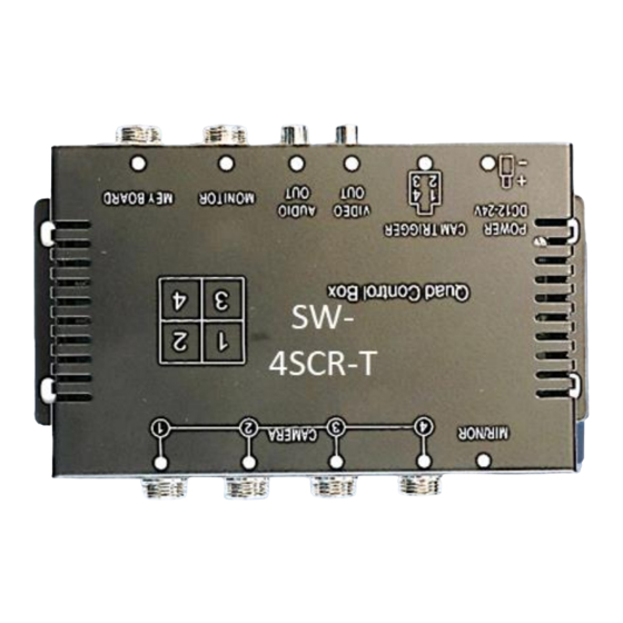
Page 4: Connectors - Video Switch Box
1.2. Connectors – video switch box Version 03.11.2021 SW-4SCR-T... -
Page 5: Dip Switch Settings
(hibernation mode) In case the sleep-mode does not succeed, the disconnection of the battery can be done with a resistor lead. The chosen +12V ACC power supply connection has to be checked for being constantly stabile. Version 03.11.2021 SW-4SCR-T... -
Page 6: Connection Schema
Connection schema 2.1. Note: The connection of any desired trigger line requires the input of a +12V trigger voltage depending on the current driving mode! Version 03.11.2021 SW-4SCR-T... -
Page 7: Connection - Power, External Keypad And Monitor
Connect the female 4-pin connector of the external keypad to the male 4pin connector of the video switch box. Note: An eventually existing audio signal from a connected video will be given out at the female cinch connector "AUDIO OUT". Version 03.11.2021 SW-4SCR-T... -
Page 8: Connection - Cameras
Note: The selection of the slots "Camera 1-4" must be made according to the desired positions in the display mode (see chapter "Display mode - Monitor"). Version 03.11.2021 SW-4SCR-T... -
Page 9: Connection - Trigger Cables
Connect the female 4pin connector of the 4-pin trigger harness to the male 4pin connector "CAM TRIGGER". Connect the +12V output voltage corresponding to the respective driving mode to the camera trigger line 1 to 4 assigned to the previously selected display mode (see also "Display mode monitor"). Version 03.11.2021 SW-4SCR-T... - Page 10 Switched to stand-by mode, the system will interrupt the power supply to the four cameras. By trigger cable activated channels will always be displayed on the monitor, regardless of the switch box power status. While a channel is triggered by cable, the manual switching is out of function. Version 03.11.2021 SW-4SCR-T...
-
Page 11: Display Mode - Monitor
Note: To the system connected sources must have only one and the same input signal, otherwise this function cannot work! Version 03.11.2021 SW-4SCR-T... -
Page 12: Technical Support
Technical Support Please note that direct technical support is only available for products purchased directly from NavLinkz GmbH. For products bought from other sources, contact your vendor for technical support. NavLinkz GmbH distribution/techdealer support Heidberghof 2 D-47495 Rheinberg +49 2843 17595 00 Email mail@navlinkz.de...
Need help?
Do you have a question about the SW-4SCR-T and is the answer not in the manual?
Questions and answers