Table of Contents
Advertisement
Quick Links
Advertisement
Table of Contents

Subscribe to Our Youtube Channel
Related Manuals for Meyra Ortopedia 1.054


Summary of Contents for Meyra Ortopedia 1.054
- Page 1 Electric travelling wheelchair Model 1.054 Operating manual A BRAND FROM...
-
Page 2: Table Of Contents
Contents Meaning of the applied markers Introduction List of models Indications Specifications Adjustment Statutory regulations High-frequency radiation Overview Model: iTravel Operating module Tips for accident prevention First driving practice Safety information Handling of the electric travelling wheelchair Securing the electric travelling wheelchair Functional checks Driving Brakes... - Page 3 Operating module-functions Battery charging socket Switching the operating module on Battery voltage Battery gauge Evaluation Pre-selectable maximum speed Preselect the maximum speed Diving speed stages Joystick Drive and steering movement Decelerating the electric travelling wheelchair Keys and symbols Selecting the operation Pre-operation checks Battery charging condition Battery charging procedure...
- Page 4 Folding/Unfolding Folding Unfolding Battery pack Wheelchair transport with lithium ion batteries Transport of lithium ion batteries Safety information to lithium ion batteries Retaining strap Fastening the retaining strap Opening the retaining strap Adjustment of belt length Loading and transportation Loading Transport of people inside a motor vehicle Transport security Maintenance schedule...
- Page 5 Technical data Maximum range Hill climbing ability Normative specifications Values acc. to ISO 7176-15 for model 1.054 Further technical data for model 1.054 Meaning of the labels on the electric travelling wheelchair Meaning of the symbols on the type plate Inspection certificate Warranty / Guarantee Warrantee / Guarantee section...
-
Page 6: Meaning Of The Applied Markers
MEANING OF THE AP- our products can be found in the < Informa- tion center > on our website: PLIED MARKERS < www.meyra.com >. Safety instructions with a coloured back- ground are mandatory and need to be LIST OF MODELS observed under any circumstance! ☞... -
Page 7: Use
ADJUSTMENT The electric travelling wheelchair is driven Always have adaptation and adjustment through the joystick that is integrated in work carried out by a specialist dealer. the operating module. The electric travelling wheelchair offers Avoid abrupt starts of your electric travel- manifold adjustment possibilities to indi- ling wheelchair. -
Page 8: High-Frequency Radiation
HIGH-FREQUENCY RADIATION Our electric vehicles are conform with the corresponding requirements of the EG-di- rective 93/42 EWG for medical devices. Nev- ertheless Interferences from high frequency rays of other electric devices cannot gener- ally be ruled out. Despite tested protective measures on the electrical equipment of the vehicle, distur- bances in the operation cannot be ruled out when driving through extreme elec-... -
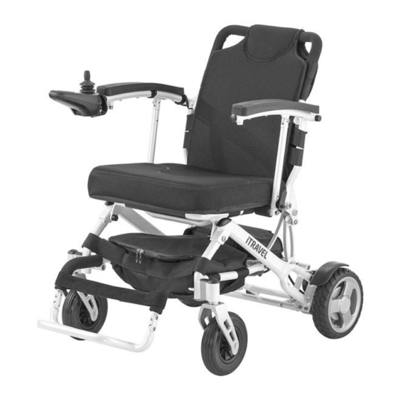
Page 9: Overview
OVERVIEW Model: iTravel The overview shows the most important components and operating devices of the electric travelling wheelchair. Pos. Description (1) Back support (2) Arm support (3) Seat pad (4) Utensils bag (5) Footplate (6) Calf strap (7) Steering wheel (8) Operating module (9) Driving wheel (10) Drive... -
Page 10: Operating Module
OVERVIEW Operating module The overview shows the operating controls of the operating module. Pos. Description (1) Operating module (2) Battery charging socket (3) Joystick (4) Reducing the adjusted speed preselec- tion (5) Horn (6) Control display of the battery capacity and fault indicator (7) Switching the operating module on/off (8) Control display of the adjusted prese-... -
Page 11: Tips For Accident Prevention
TIPS FOR ACCIDENT ☞ Do not submit the electric travelling wheelchair to extreme whether condi- PREVENTION tions. Only transfer into or out of the seat ☞ Temperature influence through lamps, when the electric travelling wheelchair sun and other sources of heat can dam- is switched off and the selection lever age the upholstery and revetment or drive-/push mode on both sides is in drive... -
Page 12: Handling Of The Electric Travelling Wheelchair
HANDLING OF THE BRAKES ELECTRIC TRAVELLING Decelerate your electric travelling wheel- WHEELCHAIR chair carefully and in good time. This is es- pecially the case when driving in front of Securing the electric travelling people and while driving downhill! wheelchair Service brake The electric travelling wheelchair is to be se- The motors work electrically as operating cured as follows to prevent it from rolling off... -
Page 13: Locking The Brakes
Locking the brakes To lock the electric travelling wheelchair always slide both levers for drive-/push mode into drive mode. It should not be possible to push the elec- tric travelling wheelchair forward when both brakes are locked. Do not switch to push mode while driving on slopes. -
Page 14: Drive-/Push Mode
DRIVE-/PUSH MODE Only switch the electric travelling wheel- chair to push mode when it is standing still for positioning or in case of emergen- cies, but not on slopes/hills. After push mode do not forget to switch the drive back to drive mode. Otherwise there is the danger of your electric travel- ling wheelchair unintentionally rolling off. -
Page 15: Operating Module-Functions
OPERATING MODULE-FUNCTIONS Battery charging socket Do not insert other objects into the bat- tery charging socket. – Danger of short circuit! To charge the lithium ion batteries first switch off the operating module. Then in- sert the plug of the battery charger into the charging socket (1) on the front of the oper- ating module. -
Page 16: Battery Voltage
Battery voltage The battery indicator displays the battery voltage after the system test performed by the electronic system after the operating module has been switched on (3). Less LED segments of the battery gauge are lit as the battery voltage reduces. Battery gauge The battery gauge (3) displays the existing battery voltage as follows:... -
Page 17: Pre-Selectable Maximum Speed
Pre-selectable maximum speed Danger of accident due to unsuitable set- ting of the preselected speed! After switching on the operating module, the maximum speed setting will be the same as that selected before switching off. Preselect the maximum speed By pressing the keys (1) and (2) the pre-se- lectable final speed can be decreased or increased. -
Page 18: Joystick
Joystick Only move the joystick when the battery indicator (2) shows a constant light. Drive and steering movement The electric travelling wheelchair is acceler- ated and braked with the joystick (1). Move the joystick slowly in the desired driving di- rection. -
Page 19: Keys And Symbols
Keys and symbols ON / OFF Switches the operating module on or off when pressing the key. ☞ The electronic will conduct a system test when switched on. ☞ Do not motion the joystick during this time. Horn A signal sounds for as long as the key is pressed. Max. -
Page 20: Selecting The Operation
SELECTING THE OPERATION In order to obtain operational readiness of the electric travelling wheelchair the follow- ing directions are to be carried out in the indicated order. Unfold the electric travelling wheel- chair if applicable. 2. Before first use, charge the drive batter- ies completely through the operating module [1]. -
Page 21: Pre-Operation Checks
6. Switch the operating module on. Press the On/Off-key (5) on the control panel of the operating module. ☞ Therefore observe chapter Switch- ing the operating module on on page 15. PRE-OPERATION CHECKS Before starting to drive, the following should be checked: The technical condition of the electric travelling wheelchair. -
Page 22: Battery Charging Procedure
Battery charging procedure Do not insert any objects other than the battery charger plug into the battery charging socket. – Danger of short circuit! Use only the included lithium charge to charge the lithium ion batteries. The guarantee is only preserved to its full extent when the included battery charg- er, supplied by us is used. - Page 23 Secure the electric travelling wheel- chair. ☞ Therefore observe chapter Securing the electric travelling wheelchair on page 12. 2. If applicable insert the main plug (2). ☞ The charging procedure is only pos- sible with inserted battery plug (2). Insert the plug of the charger into an expertly installed power outlet.
-
Page 24: Calf Belt
CALF BELT Do not drive without the calf belt. – Dan- ger of accidents. The removable calf belt (1) prevents the feet from sliding off the back of the footboard. Removing the calf belt To remove the calf belt, open the velcro fas- tener. -
Page 25: Back Support Belt
BACK SUPPORT BELT Fitting the back belt The overlapping of the Velcro fastener has to be at least 10 cm! The tension of the back support is adjust- able. Pull off the flap of the back support and fold it to the front [1]. 2. -
Page 26: Removing The Back Support Upholstery
Removing the back support upholstery For removal, first pull off the rear part of the back support upholstery, then fold it over to the front [1] and pull it off of the adjustable back strap (2) [3]. Placing the back support upholstery For applying, place the back support up- holstery centred around the upper back... -
Page 27: Seat Pad
SEAT PAD The seat cushion is attached to the seat belt with velcro fasteners [1]. UTENSILS BAG The utensil pouch is attached to the chassis frame with velcro fasteners [2]. -
Page 28: Arm Supports
ARM SUPPORTS The arm supports can be swivelled upward [1]. Swivel up the arm supports Do not grab into the cross-brace angles to swivel the arm supports. – Danger of jamming! For swivelling up the arm supports, pull the respective locking device (2) outward. Pull the locking device (2) outward. -
Page 29: Folding/Unfolding
FOLDING/UNFOLDING Do not grab into the cross sections for folding/unfolding. – Danger of jamming! For storage or transport e. g. in a motor ve- hicle the electric travelling wheelchair can folded easily [1]. Folding Switch the electric travelling wheelchair off. ☞... - Page 30 4. Switch to push mode [5]. Operate the cable pull (6) and fold the electric travelling wheelchair together toward the front [7]. ☞ The parts that might have been de- tached for the transport must be care- fully stowed and carefully attached again before the next journey! 6.
-
Page 31: Unfolding
Unfolding If applicable open the folding fixation. 2. Pull the folded electric travelling wheel- chair backwards while lifting and in this way raise it up again [1]. ☞ The locking device of the cord pull (2) has to engage audibly. Check the function of the locking de- vice. - Page 32 6. Fold the footboard down [6]. Swivel the folding lock outwards (7).
-
Page 33: Battery Pack
BATTERY PACK Optionally the electric travelling wheelchair can e equipped with two lithium ion bat- teries. The battery pack is removable [1]. Secure the electric travelling wheel- chair. ☞ For this observe chapter Securing the electric travelling wheelchair on page 12. 2. -
Page 34: Wheelchair Transport With Lithium Ion Batteries
Wheelchair transport with lithium Transport of lithium ion batteries ion batteries Protect the lithium ion batteries so that neither moisture nor foreign objects (e.g. Protect lithium ion batteries from temper- small metal parts, nails or other conduc- atures outside of the approved tempera- tive materials) can get into the gaps of the ture range for transport as well as storage. - Page 35 ☞ Therefore view chapter Further technical data for model 1.054 on page 49. Should the rare case of overheating or a fire in the lithium ion battery occur, the battery manufacturer recommends plen- ty of water or sand for extinguishing. Use only the included lithium charge to charge the lithium ion batteries.
-
Page 36: Retaining Strap
RETAINING STRAP The retrospective assembly of a retaining strap is only to be carried out by a special- ist workshop! The retaining strap [1] serves to hold a person sitting inside the electric travelling wheelchair in place. – Additional stabilisation of the sitting position. -
Page 37: Loading And Transportation
< Electric vehicles > chapter < Ramps and lifting platforms >. – This document and further information are available in the < Infozentrum > on our website < www.meyra.com > Transport of people inside a mo- tor vehicle Your individual electric travelling wheelchair is not suited as a seat for transport inside a motor vehicle. -
Page 38: Maintenance Schedule
MAINTENANCE SCHEDULE WHEN WHAT REMARK Before starting out General Carry out test yourself or with a helper. Test for faultless operation. Checking the magnet- Carry out test yourself or with ic brake a helper. Switch the selection le- If the electric travelling wheel- ver drive- / push mode to chair can be pushed, have the drive mode. -
Page 39: Wheels
Wheels Damaged wheels are to be replaced im- mediately through new wheels by a spe- cialist dealer. ☞ Always replace wheels in pairs. Two differently worn tyres [1]+[2] encumber the straight forward course of the electric travelling wheelchair. -
Page 40: Fault Correction
Fault correction Fault Cause Remedy Battery indicator on the Operating module defec- Have it repaired by the operating module does tive specialist workshop not light up after the switch-on. Plug connection of the Check the plug connec- power supply without tions. -
Page 41: Error Diagnostics
ERROR DIAGNOSTICS Operating module < LED > Error illustration through the battery gauge In case of an error the electric travelling wheelchair is shut down for safety reasons and the LEDs of the battery gauge (1) blink. The number of blink impulses indicate the possible fault source. - Page 42 Fault Cause Remedy 6 blink impulses The drive disable function Remove the charger from the is active. battery charging socket. The drive disable function is an electronic security function that prevents the wheelchair from be- ing driven when a battery charger is connected.
-
Page 43: Service
SERVICE Should the coating be damaged with scratches or similar, these areas can be touched up with our paint pen available at Cleaning and maintenance the specialist dealer. Do not clean the electric travelling wheel- Slight lubrication of moving parts will en- chair with a high-pressure cleaner! –... -
Page 44: Reinstallment
Reinstallment Customer Service Before reinstallment the electric travelling In case you have questions or require help, wheelchair is to undergo a complete in- please contact your local specialist dealer, spection. who will provide counselling, customer ser- vice and repairs. ☞ The hygienic measures required for reinstallment are to be carried out in Spare parts correspondence with the validated hy-... -
Page 45: Disposal
Disposal ☞ Lithium ion batteries are special waste. The disposal must comply with the respec- tive national law. Please enquire about local disposal arrange- ments at your municipal authority. -
Page 46: Information For The Specialist Dealer
Programming the driving behaviour Information for the specialist dealer The driving behaviour of the electric trav- elling wheelchair can be adjusted through A maintenance and service manual is availa- the programming device. ble upon demand, in which you can for ex- ample find the following information: ☞... -
Page 47: Technical Data
TECHNICAL DATA In practical use, the maximum range under 'normal conditions' is then reduced to ap- prox. 80 – 40 % of the nominal value. Maximum range The maximum range depends to a large ex- Hill climbing ability tent on the following factors: Gradients in excess of the permitted values (e.g. -
Page 48: Values Acc. To Iso 7176-15 For Model 1.054
Values acc. to ISO 7176-15 for model 1.054 min. max. Overall length 970 mm 970 mm Overall width 560 mm 650 mm Overall height 870 mm 870 mm User weight (incl. additional load) 120 kg 120 kg Overall dimensions 170 kg 170 kg Actual seat depth 400 mm... -
Page 49: Further Technical Data For Model 1.054
Further technical data for model 1.054 min. max. Sound level 62 dB(A) Protection class IP 51 Turning area 1030 mm – mm Drive controller 24 V / 45 A Engine output (6 km/h) 2x 200 W 2x 200 W Additional load –... - Page 50 min. max. Steering wheel 178 x 45 mm (7“ x 1.75") puncture safe Driving wheel 203 x 51 mm (8“ x 2") puncture safe Drive batteries 1 x 24 V 10.4 Ah Lithium ion battery Amount of energy 269 Wh Max.
-
Page 51: Meaning Of The Labels On The Electric Travelling Wheelchair
Meaning of the labels on the electric travelling wheelchair Attention! Read the operating manuals and other provided documen- tation. Do not lift the electric travelling wheelchair using the arm supports or revetment. Removable parts are not suitable for carrying. Drive mode Push mode Push only on level surfaces. -
Page 52: Meaning Of The Symbols On The Type Plate
Meaning of the symbols on the type plate Manufacturer Order number Serial number Production date Permitted user weight max. permissible total weight Permitted axle weights Max. permissible rising gradient Max. permissible falling gradient Permitted maximum speed The product is approved as a seat within a motor vehicle Max. -
Page 53: Inspection Certificate
INSPECTION CERTIFICATE Recommended safety inspection 1st year (at least every 12 months) Vehicle data: Stamp of specialist dealer: Model: Signature: Delivery note no.: Place, date: Serial-no.(SN): Next safety inspection in 12 months Date: Recommended safety inspection 3rd year Recommended safety inspection 2nd year (at least every 12 months) (at least every 12 months) Stamp of specialist dealer:... -
Page 54: Warranty / Guarantee
WARRANTY / GUARANTEE Attention: Failure to observe the instructions in the operating manual, improperly car- We accept legal liability for this product ried out maintenance work and, espe- within the scope of or general terms and cially, technical changes and additions conditions and warranty and in certain cas- (add-ons) carried out without our prior es other verbal resp. -
Page 55: Warrantee / Guarantee Section
Warrantee / Guarantee section Please fill out! Copy if necessary and send the copy to the specialist dealer. Warranty / Guarantee Model designation: Delivery note no.: SN (view type plate): Date of delivery: Stamp of the specialist dealer: Inspection certificate for transfer Vehicle data: Serial-no.(SN): Stamp of specialist dealer:... - Page 56 Your specialist dealer MEYRA GmbH Meyra-Ring 2 32689 Kalletal Kalldorf GERMANY +49 5733 922 - 311 +49 5733 922 - 9311 info@meyra.de www.meyra.de 205 347 001 (Status: 2019-07) All technical modifications reserved. Original operating manual.
Need help?
Do you have a question about the Ortopedia 1.054 and is the answer not in the manual?
Questions and answers