
Subscribe to Our Youtube Channel
Related Manuals for YOKOGAWA FLXA402T


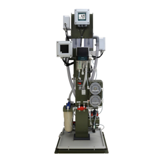
Summary of Contents for YOKOGAWA FLXA402T
- Page 1 User’s Manual FLXA402T Liquid Analyzer for Turbidity and Chlorine Operation of Converter IM 12A01G01-03EN IM 12A01G01-03EN 1st Edition...
-
Page 2: Introduction
Thank you for purchasing the FLXA 402T Liquid Analyzer for Turbidity and Chlorine. This User’s Manual contains all essential information for the user to make full use of FLXA402T. Please read the following respective documents before installing and using the FLXA402T. - Page 3 • No part of the user’s manuals may be transferred or reproduced without prior written consent from YOKOGAWA. • YOKOGAWA reserves the right to make improvements in the user’s manuals and product at any time, without notice or obligation. • If you have any questions, or you find mistakes or omissions in the user’s manuals, please contact our sales representative or your local distributor.
- Page 4 : identifies connected sensors to 1st or 2nd input. 1-1 refers to sensor connected for 1st input. 2-1 refers to sensor connected for 2nd input. FLXA402T’s fonts Efont (c) Copyright 2000-2001 /efont/ The Electronic Font Open Laboratory. All rights reserved.
- Page 5 Adobe-Helvetica ISO10646-1 extension by Markus Kuhn <mkuhn@acm.org>, 2001-03-20 Copyright 1984-1989, 1994 Adobe Systems Incorporated. Copyright 1988, 1994 Digital Equipment Corporation. Adobe is a trademark of Adobe Systems Incorporated which may be registered in certain jurisdictions. Permission to use these trademarks is hereby granted only in association with the images described in this file.
-
Page 6: Table Of Contents
Toc-1 FLXA402T Liquid Analyzer for Turbidity and Chlorine Operation of Converter IM 12A01G01-03EN 1st Edition CONTENTS Introduction ....................i Operation ....................1-1 Language ......................1-3 Date/Time setting ....................1-4 Password ......................1-5 Screens ...................... 2-1 Home screen ...................... 2-5 Main screen ....................... 2-6 Monitor screen .................... - Page 7 Toc-2 4.4.2 Maintenance ..................4-12 4.4.3 Wash ....................4-12 4.4.4 Auto wash/cal status ................ 4-12 4.4.5 Range contact .................. 4-13 4.4.6 Fail ....................4-13 4.4.7 Simulate ................... 4-14 4.4.8 Fail safe .................... 4-14 4.4.9 Off ..................... 4-14 Display settings ....................4-15 4.5.1 Display 1, 2, 3, 4 settings ..............
-
Page 8: Operation
Sample image of startup screens NOTE It takes more than ten seconds for the startup screen to switch to Home screen after FLXA402T is powered on. If any incompatible sensor is connected, an alarm appears to indicate inappropriate setting or measurement error. - Page 9 <1. Operation> Getting started Before starting measurement, check initial parameters, device selection and confirm they comply with the specification you choose. For further information on setting parameters or others, go to Chapter 4 and Chapter 5. We recommend that you follow the next order to be ready for measurement.
-
Page 10: Language
<1. Operation> Language English is set to the factory default. Select your preferred language out of the following: Chinese, English, French, German, Japanese, Korean, Portuguese, Spanish (in alphabetical order) Language screen is always displayed in English no matter what language you choose. How to select language 1. -
Page 11: Date/Time Setting
<1. Operation> Date/Time setting Singapore Time (SGT) is set to factory default in FLXA402T. We recommend setting or changing date and time to local time to use logbooks or trend graph. Go to Home/Main screen > “Menu” > Converter menu >... -
Page 12: Password
<1. Operation> Password Password security gives only authorized administrators access to data. Password is not included in factory default. You will need to establish one to secure the system. See 5.4 for further information on setting password. There are two types of password, Commissioning or Execute. * After you create password, a password prompt appears if you enter the following item: Commissioning “Setting”... - Page 13 Blank Page...
- Page 14 <2. Screens> Screens Screens Home screen Home screen displays the multiple sensor measurement status on a single page. See section 2.1. Figure 2.1 Sample image of Home screen Main screen Main screen displays a process status of one sensor connection on a single page. See section 2.2.
- Page 15 <2. Screens> Detail “Detail” provides graphic displays of multiple output status. See 3.1 See each corresponding manual for information on sensor detail screen. Figure 2.4 Sample image of Detail Trend “Trend” displays a trend chart that shows the progress of some value over a certain period of time.
- Page 16 <2. Screens> Screen Flow Chart (Home/Main/Monitor) Home screen Main screen Main screen Monitor screen Monitor screen 1st item Second item Figure 2.6 Flow chart sample NOTE If there is no touch operation for 10 minutes (default) or 60 minutes, the screen automatically returns to Monitor screen, or Home/Main screen when Monitor Display is “Off”.
- Page 17 <2. Screens> Navigation CAUTION When tapping on screen, do not use a tool with a sharp tip (e.g. pencil, ballpoint pen), a thin stick, a tool with a hard tip etc. to avoid scratches on the touch screen. Navigate icons Returns to Home screen.
-
Page 18: Home Screen
<2. Screens> Home screen On Home screen FLXA402T assigns sensor connection numbers to up to 4 measurements respectively. Home screen shows up upon startup when more than two sensor connections are defined for display. If only one sensor connection (1) is set to display, Home screen does not appear. -
Page 19: Main Screen
<2. Screens> Main screen On Main screen, FLXA402T assigns sensor connection numbers to up to 4 measurements respectively. Main screen shows up upon startup when only one sensor connection (Sensor connection number 1) is defined for display. When more than two sensor connections are defined for display, tap a preferred sensor connection number on Home screen, Main screen of the selected sensor connection appears. - Page 20 <2. Screens> When an error occurs, the screen flashes. When you set the flashing funcion off for error occurrenece, the screen will not flash. If there is no touch operation for a certain fixed period of time, (auto return default is 10 minutes), the screen returns to Main screen automatically.
-
Page 21: Monitor Screen
Sample image of Monitor screen A: 1st item (Measurement value) B: 1st item unit C: Sensor connection number. D: Display name (user programmable) *1: When FLXA402T is assigned, is displayed. (see 4.5.1) IM 12A01G01-03EN 1st Edition : Mar. 25, 2021-00... -
Page 22: Alarms
<2. Screens> Alarms Present errors in the converter/sensors are diagnosed and displayed on Home / Main screen. When you set on the alarm flashing function, the screen keeps flashing until no error is detected. Home Screen Main Screen Errors sample A: Main alarm most critical alarm at the moment they happen, including sensors’... - Page 23 2-10 <2. Screens> Figure 2.11 Sample of alarms and Remedy A: Alarms in progress, listed top to bottom in order of seriousness B: Main alarm (most critical alarm at the moment they happen including sensors’ one) C: Sensor connection number D: Title 1: Home (to Home screen) 2: Display switch...
-
Page 24: Converter Menu
<3. Converter menu> Converter menu Go to Home/Main screen> > Converter menu. There you can go to Detail, Trend, Setting (parameter list). Figure 3.1 Converter menu. Each number corresponds to the section in this manual. Detail (Converter) Home/Main screen > “Menu”... - Page 25 <3. Converter menu> Figure 3.3 Flow chart (example, Converter menu>Detail) Displayed only when relay module is in use. There are pages as many as the number of connected sensors IM 12A01G01-03EN 1st Edition : Mar. 25, 2021-00...
- Page 26 <3. Converter menu> Analog output For setting mA output, go to > Converter menu > “Setting” > “Converter settings” > “mA output settings” > “mA1/2/3/4” See 4.3 mA output settings for further information. mA output in HOLD shows “HOLD.” Alarms indicate the device status in trouble related to analog output.
- Page 27 Logbook of FLXA402T records history of events such as setting change, alarm on/off, and others. Logbook provides a total of 160 thousand log record. FLXA402T has HMI capacity of display up to 50 reports on sensor connection (1-1), (2-1) ,(2-2) for each. Switch the screen with...
-
Page 28: Trend
The screen displays the trend of up to 40 averages of the measurement for each time interval. FLXA402T samples the measurements every second. The trending graphic also shows the maximum, minimum and average values measured every 22.5 seconds. Time interval of each data point is changed along with the time scale. -
Page 29: Other Menu
<3. Converter menu> Time Trend area Scale Figure 3.5 Scale display Home/Main screen > > Converter menu> > Trend 1st trend graph you set at Trend setting is displayed. The drop-down list contains up to 4 parameters you set in Trend setting. Select the data you want to see by selecting from a drop-down list. -
Page 30: Converter Setting Menu
You can create password to protect each parameter. See 5.4 Password. We recommend that you write down these parameters on “User Settings Table” we provide and keep it for future use. You can download “User Settings Table” from our website. http://www.yokogawa.com/an/flxa402t/download/ IM 12A01G01-03EN 1st Edition :Mar. 25, 2021-00... -
Page 31: Lang.(Language)
FLXA402T, if necessary. See 5.1.3 Save configuration To connect a sensor to FLXA402T and display the measurement or mA output, you need to set up a communication network with sensors or assign each sensor-module address to HMI. How to reset parameters On Home/Main screen, tap to go to Converter menu. -
Page 32: Hold Operation (Manual Hold)
<3. Converter menu> Hold operation (manual Hold) FLXA402T Hold function retains mA output (mA1/mA2/mA3/mA4) values at preset ones. By default, Hold keeps values at “Last” set value. For details on mA output, see 4.3 mA output settings. For further information on Hold setting see 4.3.3 Configure Hold. - Page 33 Blank Page...
-
Page 34: Converter Settings
Converter settings We recommend that you write down parameters on “User Setting Table” we provide and keep it for future use. You can download “User Settings Table” from our website. http://www.yokogawa.com/an/flxa402t/download/ Home/Main > “Menu” > Converter menu > “Setting”> Converter settings When you go to Converter settings, the converter turns a maintenance status. - Page 35 <4. Setting converter> Table 4.1 Parameter-symbol list Symbol Parameter Description exclusive parameter for sensors for Analog sensor module for Relay module (Ad) for IO (Advanced) (RS) for RS-485 for Bluetooth Ethernet The parameter list is layered. Tapping a parameter marked “>” on its side will move down to lower layer.
- Page 36 <4. Setting converter> If the setting has problem, such as out-of-range setting, tapping locates the item with problem being highlighted in yellow. Even after you move to upper layer by tapping “<” key, you will see the corresponding item in yellow, which makes you easy to go back to the parameter concerned. Check the problem and edit the value again.
- Page 37 <4. Setting converter> Table 4.1 “Setting” menu Parameters Ref. section mA input settings (Ad) Type 4.1.1 Damping time 4.1.2 AI upper limit 4.1.3 AI lower limit Temperature 4.1.4 Conductivity C o n t a c t I n p u t settings Contact input1 Contact input Type...
- Page 38 <4. Setting converter> Parameters Ref. section Contact output settings (R) S1 (R) ― ― S1 (Alarm) 4.4.1 Process parameter slot Process parameter Setpoint Direction Hysteresis Delay time S1 (Maintenance) 4.4.2 mA output corresponded to S1 (Fail) 4.4.4 Process parameter slot Setting S1 (Simulate) 4.4.5...
-
Page 39: Ma Input Settings (Ad)
<4. Setting converter> mA input settings (Ad) First select the application of mA input from “Current”, “Temperature”, “pH” or “Conductivity””, then set 0% value, 100% value of each, according to the application. This function is available when mA input/output is “-N4” in the suffix code. When mA input/output is “-N2”, mA input is not settable. -
Page 40: Contact Input Settings
<4. Setting converter> Contact input settings Contact input settings starts Contact input wash (remote wash) or change the range of mA output. When mA Output/Input is “-N2”, only Contact input 1 is available. When mA Output/Input is “-N4”, both Contact input 1 and 2 (Ad) are available. When mA Output/Input is “-N2”, configuration of Contact input 2 (Ad) does not affect the operation. -
Page 41: Ma Output Settings
Process parameter slot FLXA402T allows multiple sensor connection, according to specification you choose. Select a process parameter sensor from “Sensor 1-1”, “Sensor 2-1”, “Sensor 2-2”, “Converter” to output. -
Page 42: Simulate
<4. Setting converter> Low: Output is fixed to 2.2 mA, set this for burn-down. High: Output is fixed to 22.0 mA, set this for burn-down When failure is detected on the sensors you set on Process parameter slot, burn is output only for the sensor. -
Page 43: Ma Output Limit Setting
4-10 <4. Setting converter> Last or Fixed Set mA output value for hold condition. Default is “Last”, or a value measured just before hold condition. Last holds a value measured just before hold condition Fixed holds a value set in” Fixed value mA” Auto hold during maintenance Select automatic hold Enabled or Disabled. -
Page 44: Contact Output Settings
4-11 <4. Setting converter> Contact output settings The following function can be assigned to the contact output. The contact output has expected lifetime of around 1 million counts. This may vary depending on contact mA or load capacity. S1/S2 : Alarm, Maintenance, Auto wash/cal status, mA Range1, mA Range2, mA Range3, Fail, Simulate, Off S1/S2 + Wash (in addition to S1/S2, Wash is available for FC800D solenoid... -
Page 45: Maintenance
4-12 <4. Setting converter> Setpoint, Direction, Hysteresis, Delay time Setpoint; This configures the value to activate contact output (S1/S2/S3: close, S4: open) when an alarm occurs. Direction: This selects “High” or “Low” to report the value is outside of the limit. Hysteresis: This configures hysteresis of measurements. -
Page 46: Range Contact
4-13 <4. Setting converter> 4.4.5 Range contact This contact indicates mA1 range status. When mA1 is set to auto range, use this range contact to check the current range status. Three types of contacts are available: mA range 1 contact, mA range 2 contact, mA range 3 contact. -
Page 47: Simulate
Process parameter slot Select sensors “Sensor 1-1” or “Sensor 2-1”. Do not use “Sensor 2-2”. Fail is output only with the sensors you select. Fail from FLXA402T is always valid. NOTE When an internal communication error occurs, a fail is output. However, the error location would not be identified whether it happened in the first or second sensor module. -
Page 48: Display Settings
Home screen sample (4 process display (left), 2 process display (right)) Assign Display 1, 2, 3, 4 to each item to display. Process parameter slot FLXA402T allows multiple sensor connection, according to specification you choose. Determine sensors to display from “Sensor 1-1”, “Sensor 1-2”, “Converter”. Don’t use “Sensor 2-2”. -
Page 49: Trend
4-16 <4. Setting converter> Additional text 1/2 On Main screen, Additional text helps you identify each measurement. However, Hold or Wash Display are prioritized. When Hold or Wash is being displayed, additional text is not displayed. Additional text can display up to 12 characters. Conductivity Unit Select whether to convert automatically or fix the conductivity subunit. -
Page 50: Other Setting On The Converter Display
4-17 <4. Setting converter> 4.5.3 Other setting on the converter display Auto Return The converter reverts to the Monitor screen (if Monitor screen is set to “Off”, reverts to Main screen), when there is no touch operation during the set time interval. You can select the interval to implement Auto Return among “Disable”, “10 min”, “60 min”. -
Page 51: Displayed Setting
4-18 <4. Setting converter> Meas. value during auto wash/cal. During automatic wash or automatic calibration on a turbidimeter/non-reagent type free chlorine meter/residual chlorine meter, this function allows you to select whether to hold current measurement readings on screen. This is a setup of measurement readings and does not affect the analog output. -
Page 52: Ethernet Setting (E)
Address CH assignment and mA output MODBUS - Converter FLXA402T as slave communicates with HOST devices, via MODBUS RS-485, or Ethernet (Modbus TCP/IP). Select a network system according to the hardware architecture you use. For further technical information on MODBUS, read TI 12A01F01-62EN. -
Page 53: Other Setting
4-20 <4. Setting converter> 4.6.3 Other setting Configure overall unit setting of the converter or sensors, and date format. Temperature Temperature: °C, °F If Model Suffix code of Country is -J, the temperature unit is always °C. NOTE Unit being used for connected Sensors is automatically changed according to the unit setting of the converter. - Page 54 4-21 <4. Setting converter> Table 4.5 Error list Location Alarm Alarm name default*1 I/O Alarm Fail safe occur Maintenance status Outputs in HOLD 1/2/3/4 mA1/2/3/4 Output Maint. status mA configuration error 1/2/3/4 System Display 1/2/3/4 setting error Setting alarm Auto wash/cal. setting error Auto start date error Contact config.
- Page 55 4-22 <4. Setting converter> Location Alarm Alarm name default*1 Chlorine High Chlorine Low Temp too high Temp too low Temp comp. range over Measure alarm pH comp. range over Cond. comp. range over Empty cell detection ME rotating stop Auto cal. result error Auto cal.
-
Page 56: Logbook Settings
<4. Setting converter> Logbook settings Logbook of FLXA402T records history of events such as setting change, calibration, alarm on/off, and others. Logbook helps you, for example, to be aware of maintenance due. Data in Logbook cannot be deleted, once it is stored. - Page 57 Blank Page...
-
Page 58: Others (Converter)
<5. Others (Converter)> Others (Converter) Home/Main > “Menu” > Converter menu > “Others” You will save/load configuration parameter files, search Sensor address, conduct Bluetooth pairing, set password. Sec. 5.1 Sec. 5.2 Sec. 5.3 Sec. 5.4 Sec. 5.5 Sec. 5.6 Sec. 5.7 Figure. -
Page 59: Save/Load
Industrial grade SD card with power failure recovery function Yokogawa part No.: A1005NL (2 GB) Note: You can use SD card under the operating condition of FLXA402T including operating temperature or humidity, but this condition does not guarantee the performance for a long period of time. CAUTION If customer provides SD card, check the card operating temperature range. - Page 60 (as of Apr. 2021) • Do not power down or pull out the SD card out of FLXA402T while importing/exporting/ updating the data memory from/to SD card. • You can enter up to 12 characters excluding file extension to create folder/file label. For sensor configuration parameter file, you can enter 10 characters.
- Page 61 <5. Others (Converter)> Table 5.2 User configuration files, extension File type File extension Set config. file .F00 Converter Configuration file .C00 Sensor Configuration file .D00 .D01 .D02 .D03 When you save configuration, a set of configuration data is stored. The set of configuration data contains one Set configuration file, one Converter Configuration file, and as many Sensor configuration file as connected sensors but up to 5 sensors.
- Page 62 <5. Others (Converter)> Sample list Figure 5.3 Sample list A: screen (the sample shows “Load configuration file”) B: Tap this icon to select sorting order. Ascending order Descending order Switch to sort in alphabetically ascending order, while sorting chronologically/ reverse chronologically C: Tap this to sort in chronological / reverse chronological order Chronological (an oldest one comes on top, newer at the bottom) Reverse chronological (a newest one comes on top, older at the bottom)
-
Page 63: Load Individual Configuration File
When Converter configuration file is loaded successfully, FLXA402T returns to Home screen. When sensor configuration file is successfully loaded, FLXA402T returns to the screen of Load individ. config. file, where you can select another file loading. -
Page 64: Load Configuration
<5. Others (Converter)> 5.1.2 Load configuration You will load configuration data of all sensors connected to FLXA402T as current configuration data. The screen of Load configuration shows present configuration set list. The figure below shows an example. Figure 5.7 Load configuration When you tap one of the item (above), a dialog box appears. -
Page 65: Save Configuration
<5. Others (Converter)> 5.1.3 Save configuration You will save current configuration (configuration set) of FLXA402T and all connected sensors. Save configuration screen shows a list of existing configuration set and [New name] in brackets. Figure 5.8 Save configuration If you tap one of these items above, a dialog appears showing the set name you selected. -
Page 66: Delete Indiv. Config. File
5.1.4 Delete indiv. config. File You can delete individual configuration file for FLXA402T or sensors, stored in FLXA402T. You cannot delete files individually stored as set-files. Go to Save/Load > Delete indiv. config. file. Select an item which has files to delete. (below) Figure 5.9... -
Page 67: Delete Configuration
5.1.6 Export all configuration You will export the memory of all configuration set stored in FLXA402T to SD card. The screen of Export all configuration shows a list of folders which exist in route directory of SD card and one [New name] folder. (below) Figure 5.12... -
Page 68: Import Configuration
If you enter a new Folder name but which already exists, a confirmation message for overwriting the data pops up. Select overwrite or cancel importing. Once you reach the limit number of user configuration files that can be stored in FLXA402T, you won’t be able to import files any more, when a warning message appears. -
Page 69: Export All Logbook
5-12 <5. Others (Converter)> 5.1.8 Export all logbook You will export log book data files to SD card. Figure 5.14 Export all logbook When you open Export all logbook, “File name” is blank. Enter a file name to export. If you enter more than one character, “Execute”... -
Page 70: Update Software
Make sure to save all of the files in one folder on your SD card. Place an update file provided by Yokogawa in a folder of your choice located on your SD card. Insert the SD card into the memory card slot of FLXA402T. -
Page 71: Search Modbus
5-14 <5. Others (Converter)> Search Modbus When you connect the converter to sensors or need to find sensor Modbus address, you can search MODBUS address of the connecting sensors. Search Modbus address by each sensor module. NOTE When multiple sensor connection is used, use the sensor with each different MODBUS address (1 to 247). -
Page 72: Password
5-15 <5. Others (Converter)> Password Protect setting, calibration and others with password. Read 1.3 Password on how to establish password. Figure 5.16 Password Both “Commissioning” and “Execute” boxes are blank by factory default. If you leave the boxes blank, password is invalid to secure operation. You can create a password with up to 12 characters. -
Page 73: Date/Time
5-16 <5. Others (Converter)> Date/Time To set date/time, see 1.2 Date/Time setting Figure 5.18 Date/Time Adjust panel You can adjust the touch position of LCD touch panel or brightness. Figure 5.19 LCD adjustment Touch panel Normally you don’t need this adjustment. When you need to calibrate the touch-screen systems, perform the adjustment properly. -
Page 74: Service Mode
Customers cannot use this mode. CAUTION Service mode is protected by password and allowed to be used only by Yokogawa engineers. Any act including attempting to breaking into the system or data modification may affect the performance of the product. - Page 75 Blank Page...
-
Page 76: Maintenance, Trouble Shooting
Contact Yokogawa service. Battery The FLXA402T has a logbook feature that uses a clock to provide the timings. The instrument contains a lithium cell (battery) to continue the clock function while the power is turned off. -
Page 77: Trouble Shooting
When you replace a fuse, be sure to power off, remove wires and shield cover. For information on fuse position, see “Name and Description” of 12A01G01-02EN. If a fuse blows soon after the replacement, contact your nearest Yokogawa service center 6.2.3 Mounting hardware, Sun shade hood After purchasing the product, you might need to purchase some optional parts, including mounting hardware or sun shade hood, because of relocation of installation site etc. -
Page 78: Revision Record
Revision Record Manual Title : FLXA402T Liquid Analyzer for Turbidity and Chlorine, Operation of Converter Manual No. : IM 12A01G01-03EN Mar. 2021/1st Edition Newly published IM 12A01G01-03EN 1st Edition : Mar. 25, 2021-00... - Page 79 Blank Page Yokogawa Electric Corporation 2-9-32 Nakacho, Musashino-shi, Tokyo 180-8750, JAPAN http://www.yokogawa.com/...
Need help?
Do you have a question about the FLXA402T and is the answer not in the manual?
Questions and answers