
Subscribe to Our Youtube Channel
Related Manuals for YOKOGAWA FC400G


Summary of Contents for YOKOGAWA FC400G
- Page 1 User’s Manual Model FC400G Free Available Chlorine Analyzer (Non-Reagent Type) [Style: S2] IM 12F5A1-01E IM 12F5A1-01E 5th Edition...
-
Page 2: Introduction
The product is provided on an “as is” basis. YOKOGAWA shall have neither liability nor responsibility to any person or entity with respect to any direct or indirect loss or damage arising from using the product or any defect of the product that YOKOGAWA can not predict in advance. Media No. IM 12F5A1-01E (CD) 5th Edition :Apr. - Page 3 Before Measurement The FC400G Free Available Chlorine Analyzer is preset with defaults prior factory shipment. Before measurement, verify that these factory default settings meet the operating conditions and if necessary, reconfigure parameters. For details of setting data, refer to chapters 5 and 6. When user changes the operation parameter, it is recommended to note down the changed data.
-
Page 4: After-Sales Warranty
If we replace the product with a new one, we won’t provide you with a repair report. l Yokogawa warrants the product for the period stated in the pre-purchase quotation Yokogawa shall conduct defined warranty service based on its standard. When the customer site is located outside of the service area, a fee for dispatching the maintenance engineer will be charged to the customer. - Page 5 Blank Page...
-
Page 6: Table Of Contents
1.2 Measuring Principle of FC400G Free Available Chlorine Analyzer ..... 1-3 2. SPECIFICATIONS ..................2-1 2.1 Standard Specifications ................... 2-1 2.1.1 FC400G Free Available Chlorine Analyzer (Non-Reagent Type) ..2-1 2.1.2 Dedicated Sampling System for (Non-Reagent Type) Free Available Chlo- rine Analyzer ..................2-3 2.2 Characteristics ....................2-3 2.3 Model and Codes ....................2-4 2.3.1... - Page 7 <CONTENTS> 4.2.3 Modes in Service level ............... 4-4 NAMES OF COMPONENTS ..............5-1 5.1 Operation Keys ....................5-1 5.2 Display Content on the Display Unit ............... 5-2 5.3 Basic Key Operation ..................5-3 5.3.1 Key Operation When Indication Blinks ...... 5-3 5.3.2 Key Operation When Indication Blinks ... 5-3 5.3.3 Mode Selection in the Operation Level ..........
- Page 8 <CONTENTS> 7.3.2 Span Calibration Using the Standard Solution Method ..... 7-7 7.4 Remedies When Errors Occur in Zero or Span Calibration ......7-8 7.4.1 If Errors occur during Calibration ............7-8 7.4.2 Remedies When an Error Occurs ............7-8 INSPECTION AND MAINTENANCE ............8-1 8.1 Inspection and Maintenance Items and Implementation Cycle ....8-1 8.1.1 Polishing the Indicator Electrode ............8-1 8.1.2 Cleaning the Ceramic Beads and Measuring Tank ......
- Page 9 Blank Page...
-
Page 10: Overview
To reduce the error in this sort of situation, we recommend that you use the combined chlorine insensitive version of the Model FC400G that has been developed for this purpose. Compared with the standard Model FC400G, the electrodes, the beads, and the applied voltage are different, but the unit is otherwise the same as the standard Model FC400G as regards measurement principles, installation, specifications and performance. -
Page 11: Configuration Of The Free Available Chlorine Analyzer
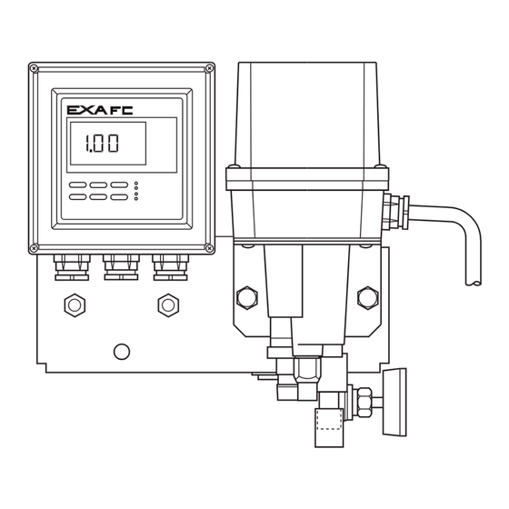
The FC400G free available chlorine analyzer is broadly divided into a free available chlorine analyzer main body (FC400G) and a sampling system: The main body consists of a detector and converter, and the sampling system consists of sample water piping and a needle valve. -
Page 12: Measuring Principle Of Fc400G Free Available Chlorine Analyzer
(sample) in comparison with the RC400G Residual Chlorine Analyzer that uses reagent. Also, note that if combined chlorine is present in sample, FC400G performance is affected. Figure 1.2 shows the measuring circuit principle of the FC400G free available chlorine analyzer. The FC400G applies voltage compensated in accordance with the diffusion current value, between the indicator and counter electrodes and measures the diffusion current flow between the electrodes. Temperature compensation is accomplished using the CPU which performs calculation based on the temperature signals received from the temperature-measuring circuit. - Page 13 Blank Page...
-
Page 14: Specifications
< 2. Specifications > 2. SPECIFICATIONS 2.1 Standard Specifications 2.1.1 FC400G Free Available Chlorine Analyzer (Non-Reagent Type) Measured Object: Free chlorine in tap water Measuring System: Polarographic method using rotating electrode Display Method: Digital (3 1/2 digit LCD) display Measuring Range: 0 to 3 mg / l Output Range: Can switch between arbitrary ranges(each between 0 to 1 mg/l and 0 to 3 mg/l). - Page 15 < 2. Specifications > pH6.5 pH7.5 FC400G Operating range Conductivity (µS/cm) Figure 2.1 Sensitivity characteristics of Figure 2.2 Sensitivity characteristics of diffusion diffusion current by pH value current by conductivity Note: If conductivity exceeds 300 µS/cm, default value of applied voltage should be changed. Electrodes : Indicator electrode; Indicator electrode The combined chlorine insensitive version uses a gold alloy indicator electrode. Counter electrode ; Silver chloride electrode (with Pt 1000 RTD installed)
-
Page 16: Dedicated Sampling System For (Non-Reagent Type) Free Available Chlorine Analyzer
< 2. Specifications > Ambient humidity: 5 to 95% RH (no dew condensation allowed) Storage Temperature: -30 to 70°C Installation: Indoor (Outdoor use separately requires rainproof measures.) (Direct sunlight must be avoided.) Utility: Power supply; 100 V AC ±10% 50/60 Hz 110 V AC ±10% 50/60 Hz 200 V AC ±10% 50/60 Hz 220 V AC ±10% 50/60 Hz Power consumption; Approx. 15 VA Mounting: 2B pipe mounting or wall mounting Weight: Approx. 6 kg EMC Regulatory Arrangement in Australia and New Zealand: EN 55011 Class A, Group 1... -
Page 17: Model And Codes
[Style: S2] Model Suffix Code Option Code Description FC400G - - - - - - - - - - - - - - - - - - - - - - Free available chlorine analyzer (non-reagent type) Output - - - - - - - - - - -... -
Page 18: Sampling System
< 2. Specifications > 2.3.2 Sampling System Model Suffix Code Option Code Description ST401G ........Sampling system System (note 3) -FC4 ....With free available chlorine analyzer (FC400G) (note 1) -PH5 ....With pH converter (PH450G) (note 2) -PF5 ....With free available chlorine analyzer (FC400G) and pH converter (PH450G) (note 1) (note 2) (note 3) Ultrasonic oscillator ....Not supplied (for pH meter) .... -
Page 19: Spare Parts
< 2. Specifications > 2.3.3 Spare Parts Replacement interval is standard and does not represent warranty of each part. Recommended Name Part No. Description Q´ ty replacement interval (*) Indicator Electrode (Rotating electrode) K9332MB Gold electrode Yearly Indicator Electrode (Rotating electrode) K9334JP Gold alloy indicator electrode Yearly Counter Electrode... -
Page 20: Dimensions
Maintenance 2B Pipe Converter space Stanchion Measuring tank 16.5 Electric connection 3-ø10.5 holes (for wall Needle valve JIS A15 plastic water-proof mounting) plug or equivalent Drain outlet Sample inlet F2.1.5E.ai (ø15 hose coupling) (Rc1/4) Figure 2.3 Dimensions of the FC400G Free Available Chlorine Analyzer IM 12F5A1-01E... - Page 21 Blank Page...
-
Page 22: Installation, Piping, And Wiring
70 mm, for the U-bolt holes. Where necessary, use a sampling system to regulate the pressure and flow of the measurement liquid. Normally the FC400G would be mounted in the sampling system in this case. Figure 3.1 shows a combination of the FC400G with a special sampling system (ST401G-FC4). When using this, refer to its instruction manual IM12A0V2-E regarding installation requirements. -
Page 23: Piping
< 3. Installation, Piping and Wiring > 3.2 Piping 3.2.1 For Use without a Sampling System When sample has a pressure of 1 to 150 kPa and a flow rate of 0.1 to 2.5 l/min, such sample can be directly introduced into the measuring tank. Connect a Ø6 X Ø4 mm polyethylene tube to the sample water inlet. Connect a Ø22 X Ø15 mm flexible mesh-reinforced tube to the drain outlet from the measuring tank. Install this tube so that no water entrapment is formed. Entrapment of water in the drain tube may cause overflow from the measuring tank. 2B Pipe Stanchion Electrical connections Measuring tank JIS A15 plastic water- proof plug or equivalent... -
Page 24: For Use With Dedicated Sampling System
< 3. Installation, Piping and Wiring > 3.2.2 For Use with Dedicated Sampling System Piping is connected to the measurement liquid inlet and drain outlet. The piping will depend on the sampling equipment. When the ST401G sampling system is to be used, refer to its instruction manual IM12A0V2-E. -
Page 25: Wiring
< 3. Installation, Piping and Wiring > 3.3 Wiring The types of wiring required by the FC400G free available chlorine analyzer (non-reagent type) are as shown below. All are connected to wiring terminals (M3 screw) in the converter. (1) Power cable and grounding wire (2) Analog output signal cable (3) Contact output (<MAINT>, <FAIL>) cables (when required) -
Page 26: Power Cable And Grounding Wire
< 3. Installation, Piping and Wiring > 3.3.1 Power Cable and Grounding Wire A power cable is used to feed power whose voltage and frequency meet the specifications for the FC400G free available chlorine analyzer converter and a grounding wire to ground the converter case. For the power cable, use a two-core cable with a finished O.D. of 9 to 12 mm to connect the power supply to converter terminals L1 and L2. The converter has no power switch; it is recommended that a double-pole single-throw switch be installed in the power line. - Page 27 Blank Page...
-
Page 28: Parts Names And Operations
< 4. Parts Names and Operations > 4. PARTS NAMES AND OPERATIONS 4.1 Parts Names and Functions <Detector> Electrode mechanism block cover prevents the corrosive gas from intruding into analyzer. Base Electrode mechanism block Fixing screws Measuring tank Ceramic beads Polish the indicator electrode to maintain the clean surface of the indicator electrode Driven shaft Drive shaft... - Page 29 < 4. Parts Names and Operations > <Converter> (*) Keystroke in operation level can be accomplished with the case cover installed. Case cover (*) Operation level indicating panel Operation keys Display unit Fixing screws F4.2e.ai Figure 4.2 Converter Parts Names (with the Cover Closed) Setting level indicating panel Setting level / Operation level selector switch F4.3e.ai...
-
Page 30: Operation Modes And Codes
MEASURE mode as ESC key. MODE (Note) Change mode by code 09. The operation of the FC400G free available chlorine analyzer (non-reagent type) is determined in the following three control levels. (1) Operation level... -
Page 31: Modes In Setting Level
Both range 1 and range 2 are set. (2) *SET .HD : Turn HOLD ON / OFF, select HOLD output (previous value, preset value). (3) *WASH : Select Manual or Auto Wash, select Timer ON / OFF, set wash interval, wash time, and stabilization (settling) time. (Since the FC400G does not use reagent, washing is not provided and wash mode is not used in the standard instrument). *AZ.CAL : Set Auto-Zero calibration, select Timer ON / OFF, set wash interval,wash time, and stabilization (settling) time. -
Page 32: Names Of Components
< 5. Key Operation and Display > 5. NAMES OF COMPONENTS All keys on the FC400G free available chlorine analyzer (non-reagent type) are available in an interactive manner. This allows easy operation that can be accomplished in accordance with displayed message indicator and operation key indicator. -
Page 33: Display Content On The Display Unit
Mode Pointer : Points to the currently selected mode. When the pointer is lit, it indicates that the relevant mode has been selected. If the pointer blinks, it indicates that the FC400G is not yet in that mode. Modes in the Operation Level ... -
Page 34: Basic Key Operation
( in the figure below), press the key to response to the message displayed on the message area ( in the figure). (Example) Blinking, indicating that the FC400G is not yet in the CAL mode. Requesting the key. Inquiring whether to enter the CAL mode. F5.3.1e.ai 5.3.2 Key Operation When... - Page 35 < 5. Key Operation and Display > Example of Data setting using the keys > > > > F5-4e.ai IM 12F5A1-01E...
-
Page 36: Mode Selection In The Operation Level
To return from the setting level to the measurement mode in the operation level, press the * key. MODE However, if the FC400G is in the hold status, transfer to the measurement mode is disabled, the FC400G returns to the <HOLD> mode. Note: The * key is available only when the FC400G is not yet in any mode in the setting level. (Example) ∗ ∗ MODE MODE OUTPUT HOLD... -
Page 37: Transfer To The Service Level
“ *SERVC ” and press the key to enter the service level. Then enter a code. To return from the service level to the measurement mode in the operation level, press the key. MODE However, if the FC400G is in the hold status, transfer to the measurement mode is disabled and the FC400G returns to the <HOLD> mode. (Example) ∗ MODE (In hold status) -
Page 38: Mode Selecting Procedure For Each Level And Mode Content
< 5. Key Operation and Display > 5.4 Mode Selecting Procedure for Each Level and Mode Content 5.4.1 Mode Selection in the Operation Level <Measurement mode> MEASURE MODE <Operation level> Calibrate? MODE Set / cancel hold? HOLD For the description of the <CAL> mode, see item (2) in 5.4.1. MODE For the description of the Select message display? <HOLD>... - Page 39 < 5. Key Operation and Display > (1) <MEASURE> (Measurement Mode) Allows concentration and message indications (one of temperature, diffusion current, applied voltage, output, slope, or zero point). (2) <CAL> (Calibration Mode) Press the key in measurement mode and enter the operation level. MODE Press the key in message indicator CAL to select the <CAL> mode. <DISP> These indications appear only when NO .
- Page 40 < 5. Key Operation and Display > (3) <DISP> (Message Display Selection Mode) Press the key and select the <DISP> mode using the key. MODE Select the message display content using the key. Temperature (°C / °F ), diffusion current (µA), applied voltage (V), output (%), slope (SL), or zero point (ZR) can be displayed. <HOLD> DISP Temperature display 25.0°C Diffusion current display 3.00 µA Applied-voltage display -0.10 V Output current 10.0%...
- Page 41 5-10 < 5. Key Operation and Display > (4) <HOLD> (Hold ON/ OFF Mode) Unless “*HLD.ON” is established in the setting level, the FC400G cannot enter this mode. Press the key and select the <HOLD> mode using the key. MODE Select setting or canceling with “HOLD.ON” displayed (press the key to set the <HOLD> mode or the key to cancel it). In the hold mode, the LCD displays the HOLD indication. <CELL> HOLD HOLD.ON Hold cancel Hold setting <MEASURE> F5-10.1e.ai (5) <CELL> (Cell Motor ON / OFF Mode) Press the key and select the <CELL> mode using the key.
-
Page 42: Modes In The Setting/Service Level And Selection Of Their Setting Items
5-11 < 5. Key Operation and Display > 5.4.2 Modes in the Setting/Service Level and Selection of Their Setting Items <Setting level> <Service level> Enter service code No. Set output range? MEASURE SERVICE OUTPUT > HOLD HOLD For the description of <* OUTPU>, see (In hold status) item (a) in 5.4.2. Set hold parameter? SETHOLD Specify a setting item... - Page 43 100.0% 2 F5-12-1e.ai (b) <*SET.HD> (Hold Parameter Setting Mode) Press the key to enter the setting level and press the key to select < *SET.HD >. * Pressing the key with “*HLD.ON” displayed causes the FC400G to enter calibration, setting level, and service level, automatically holding output. Pressing the key with “*HLD.OF” displayed cancels holding of output. When “*HLD.ON” is selected, select the value immediately preceding hold (press key with “*HD.LST” displayed) or fixed value (press key with “*HD.FIX” displayed and make setting with “*HOLD.%” displayed) as a hold output value.
- Page 44 5-13 < 5. Key Operation and Display > (c) <*WASH> (Wash mode) The standard free available chlorine analyzer (non-reagent type) has no washing function; this mode is not used. Use this mode only when the washing function is provided for special specifications. Therefore, “*T.OFF” status must be generally set. In case of special product with washing function, perform the operation with the followings. Press the key to enter the setting level and press the key to select <*WASH >.
- Page 45 5-14 < 5. Key Operation and Display > (d) <*AZ.CAL> (Auto Zero Calibration mode) The activated charcoal filter is used and auto calibration is performed. To turn this function ON, service code 09 [Wash / Auto Calibration] switch is set to “1”. The default setting is “0” for Wash. For Auto Zero Calibration mode, the calibration interval “*INT D” (unit: days), calibration setup time “*WT.min” (unit: minutes), and stabilization (settling) time “*RT.min” . (unit: minutes) are set. The optimum time settings depend on the sample and the measurement environment.
- Page 46 Measure all steps. F5-12-4e.eps (f) <*SERVC> (Service Level) Enter the key at *SERVC displayed, *CODE appears and enter the service level. Enter codes 01 ,02, 04, 05, 07, 08 and 10 needed for setting various parameters in the service level. Note: Never attempt to enter a code other than codes 01 , 02, 04, 05, 07, 08 and 10. If inadvertent entry is made, immediately press the key. Entry of any code other than 01 , 02, 04, 05, 07, 08 MODE and 10 may disable normal FC400G operation TEMP TEMP °C °F F5-12-5e1.ai IM 12F5A1-01E...
- Page 47 5-16 < 5. Key Operation and Display > FAIL FAIL Temperature compensation range exceeded fail OFF Temperature compensation range exceeded fail ON Initial setting may apply. (This causes effect whether it is set to either 0 or 1.) BURN (Not used, do not change the setting.) BURN F5-12-5e.ai ∆T.SEC...
- Page 48 5-17 < 5. Key Operation and Display > 06 Reserved Code (currently not used) DRV V -1 .0 0 Set applied-voltage compensation parameter Start. DRV V 0.0 1 Set applied-voltage compensation parameter Slope. V/µA Note : Applied voltage is controlled based on the following equation. (Applied voltage)=(Start)+(Slope)x(diffusion current value) <...
- Page 49 Blank Page...
-
Page 50: Operation
For details of wiring, refer to Sec. 3.3. 6.1.2 Filling with Ceramic Beads for Electrode Polishing Surface contamination of the indicator electrode results in measured value error. To avoid contamination-caused error, the electrode surface is continuously polished by ceramic beads during FC400G operation. Ceramic beads are not filled into the beads case at factory shipment. Thus, pour the ceramic beads provided in the accessory box into the beads case as follows before starting the FC400G. The combined chlorine insensitive version uses glass beads. -
Page 51: Supplying Sample Water
• The water should flow continuously along the whole length of the electrode , from the tip to where it enters the water ( minimum flow 0.1 l/min. ) • Liquid flow should not be such that water splashes on the base of the electrode (maximum flow 2.5 l/ min. ) Check that there is no leakage from the piping or from the breather hole of the tank. When the FC400G is used with ST401G Sampling System. The sample supply pressure should be 100 to 750 kPa, and flow should be 0.1 to 10 l/min. Adjust flow using needle valve as described in (1) above. (Note) Refer to the Instruction Manual IM12A0V2-E of the ST401G Sampling System. 6.1.4 Polishing the Indicator Electrode The electrode surface of the indicator electrode must always be kept clean. Polish the electrode... -
Page 52: Supplying Power
Before supplying power, check that the fuse holder cap in the converter is not loose. A power switch in the power line to the FC400G is used to turn power ON / OFF (the FC400G does not have any internal power switch). Be careful not to turn on the power and cause an accident with the indicator electrode or belt used to rotate it when the cover is removed or the electrodes are parked in the maintenance position shown in Figure 6.3... -
Page 53: Checking Electrode Mechanism Block
• Close BV3 and BV2 ball valve. 6.1.8 Setting Operation Parameters When the FC400G Free Available Chlorine Analyzer arrives at your site, it will operate based on the initial data set at the time of shipment. Set the appropriate parameters to suit your operation conditions. Refer to Sec. 6.3 for the types and operations of setting parameters. Key operations for displaying the setting mode items and setting data are described in Chapter 5. -
Page 54: Normal Operation
6.2.2 Shutting Down then Restarting Operation The data in the FC400G is retained even when power is disconnected. If it is to be stopped for a long period, then power should be disconnected. If power will continue to be supplied, it’s recommended that the cell motor be stopped. When restarting, perform a checkup and maintenance (see Chapter 8). -
Page 55: Requirements For Setting Operation Data
< 6. Operation > 6.3 Requirements for Setting Operation Data 6.3.1 Setting Items Table 6.1 shows different Operating and Setting items. Table 6.2 shows Setting items in Service level. Table 6.1 Setting Item List (Set Values at Shipment and Their Setting Range) -1 Initial Value Setting Item Selection and Setting Range (at Factory Shipment) Opera <DISP> (Display) Mode -tion • Message area display content selection Temperature display Sample temperature, diffusion Level current, applied voltage, output %, slope, and zero point <*OUTPU>... - Page 56 < 6. Operation > Table 6.2 Setting Item List (Set Values at Shipment and Their Setting at Range)-2 Initial Value Setting Item Selection and Setting Range (at Factory Shipment) Code 01 (*TEMP) Mode •Temperature unit selection °C ( 0 ) °C ( 0 ), °F ( 1 ) Code 02 (*FAIL) Mode •Reserved code ( 0 ), ( 1 ) Successive operation is not affected whether ( 0 ) or ( 1 ) is...
-
Page 57: Setting In The Setting Level
< 6. Operation > 6.3.2 Setting in the Setting Level Unscrew four screws in the front panel of the FC400G converter to remove the converter case cover. Then press the key to select the setting level. * Output range setting (<*OUTPU> Mode) When straight-line output is selected using SERVICE code 05, you need to set only the concentration value corresponding to output of 100% . - Page 58 < 6. Operation > • Washing Time Setting (when *T. ON is selected) Set washing time *WT.min in the range of 0.1 to 25.0 min. The washing time is set to 1.0 min at factory shipment. • Releasing Time Setting (when *T. ON is selected) Set releasing time *RT.min (time required for eliminating the effects of washing solution) in the range of 0.1 to 25.0 min.
- Page 59 To collect plateau characteristic data, select message *MEAS and press the key. Pressing the key with *MEAS displayed causes the FC400G to enter *READ. Pressing key again calls up the previously collected data in turn. • Setting Initial Applied-voltage (when *MEAS is selected) Set initial applied-voltage *INI V in the range of -1.00 to 1.00 V.
-
Page 60: Setting In The Service Level
6-11 < 6. Operation > 6.3.3 Setting in the Service Level Press the key to enter the service level on *SERVC display in Setting Level. Enter a code in the service level to enter the service mode. Code 01: Selecting Temperature Unit (°C / °F) (*TEMP Mode) Set temperature unit to “0”... - Page 61 6-12 < 6. Operation > Code 07: Setting Applied-voltage Compensation Parameters (*DRV V Mode ) In the free available chlorine analyzer, optimum applied-voltage value changes in proportion to the diffusion current value as shown in the plateau characteristic in Figure 6.8. This requires applied-voltage compensation be made as expressed by the following equation. ( Applied voltage ) = ( DRV V ) + ( V/ µA ) x ( diffusion current value ) Optimum applied-voltage Current V / µA Applied voltage DRV V F6.8e.ai Figure 6.8 Plateau Characteristic of the Free Available Chlorine Analyzer...
-
Page 62: Calibration
Also, calibration is performed periodically (recommended every month or so) during operation. This chapter describes the calibration procedure. 7.1 Running-in In general, calibration requires running-in. Always run in the FC400G at start-up or when it restarts after being temporarily stopped. Running-in requires, first, polishing of the indicator electrode. Comply with Sec. 6.1.4 on how to polish the indicator electrode. -
Page 63: Method Of Zero Calibration Using Open Input Circuit Method
< 7. Calibration > 7.2.1 Method of Zero Calibration using Open Input Circuit Method This section describes zero calibration using open input circuit method. Note: This section also explains how to stop the indicator electrode when electrode mechanism block is moved. It is not necessary to stop the indicator electrode for the purpose of calibration, but rather _ before lifting out the electrode mechanism block or moving the unit _ to eliminate the chance of the electrode hitting something while rotating. -
Page 64: Method Of Zero Calibration Using Chlorine-Free Water
Connect piping to supply chlorine-free water to the FC400G. Close the needle valve at the sample water inlet of the FC400G, and remove the sample water piping from the joint to the measuring tank. Release any sample water remaining in the measuring tank by opening the drain cock on the tank. Use tubing and hardware to connect the chlorine-free water tank to the sample water inlet. Use a head difference or a pump to supply... - Page 65 < 7. Calibration > NOTE During Auto calibration, if the key or key are pressed then Auto calibration is * MODE aborted, and immediately the analog output hold is released, <HOLD> and <CAL> go OFF, and the <MAINT> contact output goes OFF. The calibration interval timer is reset to zero. When the following conditions are true, the calibration interval timer starts to count from 0 to its “count up”...
- Page 66 < 7. Calibration > • Power is ON and zero filter flushing start conditions are satisfied. • Auto zero calibration interval is at least one day and Auto calibration functions are ON. • When Auto calibration functions are ON and Auto zero calibration interval is changed to at least one day. •...
-
Page 67: Span Calibration
Start span calibration at the point when zero calibration using the method in 7.2.1 or 7.2.2 is Sec. finished and “SPAN” is displayed in the message display. Note: When calibration described in Sec. 7.2.1 is performed, the FC400G is in the MEAS mode (or in the <HOLD> mode) and “SPAN” is not displayed. Refer to (b) in Sec. 5.4.1 and display “SPAN” in the <CAL> mode. Press the key to enter the span calibration mode. -
Page 68: Span Calibration Using The Standard Solution Method
Note: If an error occurs during calibration operation, “END.E5” or “END.E7” is displayed in the message. When this message is displayed, take countermeasures, referring to Sec. 7.4. Press the key to end the calibration and switch the FC400G to the MEAS mode. Press the key to switch the FC400G to the <MEASURE> or <HOLD> mode (“HOLD. -
Page 69: Remedies When Errors Occur In Zero Or Span Calibration
<MEASURE> mode. 7.4 Remedies When Errors Occur in Zero or Span Calibration 7.4.1 If Errors occur during Calibration If error occurs during zero or span calibration, the FC400G free available chlorine analyzer displays FAIL on the LCD and generates an error message as follows: (1) During Zero Calibration “END.E6” : Zero point error (Err.6) “END.E7” : Response error during the calibration (Err.7) During Span Calibration “END.E5”... -
Page 70: Inspection And Maintenance
< 8. Maintenance > INSPECTION AND MAINTENANCE This chapter describes the inspection and maintenance required to maintain the FC400G operation in good condition. 8.1 Inspection and Maintenance Items and Implementation Cycle The table below shows the principal inspection and maintenance items and recommended maintenance intervals to maintain good operating condition. - Page 71 < 8. Maintenance > shown in Figure 8.2. The electrode mechanism block is fixed to the measuring tank using two screws at the lower part of the mechanism block. Electrode mechanism Electrode block cover mechanism block Fixing screws (2 pcs) Figure 8.1 Electrode Mechanism Figure 8.2 Under Maintenance Block Fixing Screws (2) Removing the Indicator Electrode Remove the electrode mechanism block cover from the detector. Hold the gears so that the drive shaft does not turn and remove the indicator electrode. The electrode is screwed into the drive shaft;...
-
Page 72: Cleaning The Ceramic Beads And Measuring Tank
After polishing the indicator electrode, calibrate the zero point and span in the manner described in Chapter 7. It is recommended that calibration be conducted every month in the initial stage of FC400G operation to determine the degree of contamination on the indicator electrode. This may be a guidance for determining appropriate maintenance intervals. -
Page 73: Replacement Of Activated Charcoal Filter
< 8. Maintenance > 8.1.4 Replacement of Activated Charcoal Filter (1) Close BV1 and BV2, then rotate filter case to remove (see Figure 8.4). (2) Clean inside of case with brush or the like. (3) As illustrated in Figure, replace filter with new one. (4) Reassemble using the reverse procedure, then open BV3 and BV1 to pass water through filter. Check that there are no water leaks from filter and piping, and no bubbles in drain water. (5) Operate for about 20 min. then confirm that free available chlorine analyzer reading is near zero. -
Page 74: Check/Maintenance/Replacement Of Rotating Contact
< 8. Maintenance > 8.2.1 Check/Maintenance/Replacement of Rotating contact CAUTION Never touch Rotating contact except when replacement is performed. When you hold Rotating contact, pinch it with two fingers and never touch the center contact part. Never drop it or gives a shock. Contact part CAUTION The storage limit for Rotating contact is 1 year after the purchase, considering degradation of the lubricant used inside. Store it in room temperature and keep it away from direct sunlight. [Checks and Maintenance] Rotating contact does not need inspection. Never contact the rotating contact except when the replacement is performed. -
Page 75: Check / Maintenance / Replacement Of Drive Belt
(5) Install wiring terminals of Rotating contact on the block terminal of Rotating contact. Be sure that the wiring never contacts the drive belt. (6) F eed power to FC400G. Confirm that the driven shaft/drive shaft/drive belt/rotates smoothly, and that there are no abnormal sounds, like vibration or discontinuous noises. -
Page 76: Check/ Maintenance/ Replacement Of Driven Shaft Assembly
[Replacing the driven shaft assembly] If the bearing has become bad, replace the driven shaft assembly. In principle,this should be done by Yokogawa’s service facility. If the user wishes to replace it, the procedure is as follows: Items (1) to (9) relate to disassembly, and items from (10) onwards relate to reassembly. - Page 77 (Note) If the indicator electrode is contacting the base, or if the hole in the center of the base and the center of the indicator electrode are not aligned, loose the four screws on the motor mounting base and adjust. (15) Remount counter electrode, reconnect wiring in place, and fix clamp. This completes the replacement procedure. Feed power to FC400G. Check that the drive shaft/drive belt/driven shaft rotates smoothly and there is no abnormal noise like vibration or intermittent sound.
-
Page 78: Check / Maintenance / Replacement Of Motor And Gear Head
If operation is still not satisfactory, replace motor and gear head. [Replacement procedure] Replacement of motor and gear head should, in principle, be carried out by Yokogawa service. If you want to do it yourself, the procedure is as follows: • In principle, replace motor and gear head at the same time as periodic replacement of other parts. - Page 79 Blank Page...
-
Page 80: Troubleshooting
< 9. Troubleshooting > 9. TROUBLESHOOTING 9.1 When <failure> is Indicated Daily maintenance for maintaining good FC400G operation is described in Chapter 8; this chapter sets forth how to maintain the FC400G in the event of error. 9.1.1 Indication of Error Message or Error Code Types of <failure> and respective error messages / error codes are listed in Table 9.1. • Errors occurring during Measurement If error occurs during measurement, the LCD displays an error message (Err. - Page 81 < 9. Troubleshooting > Err. 1: (Diffusion Current Value Exceeded) “Err. 1” appears if the diffusion current during measurement exceeds the range of -9.00 to 26.00 µA. Confirm if the applied voltage parameter value set in service code 07 is correct. Also, confirm that there is no grime or moisture adhesion resulting in insulation deterioration on the electrode cable connection. Err. 2: (Sample Temperature Error) “Err. 2” appears if sample temperature exceeds the range of 0.0 to 50.0°C. Control sample temperature to be in the range of 0.0 to 50.0°C. If the error indication fails to extinguish even when the sample temperature is in the range of 0.0 to 50.0 °C, RTD is possibly defective (open circuited). In this case, replace the counter electrode. Err. 4: (Applied Voltage Error) “Err. 4” appears if the applied voltage output exceeds the range of -1.5 to 1.5 V.
- Page 82 < 9. Troubleshooting > Err. 10: (Converter failure) The FC400G free available chlorine analyzer has become defective. Contact Yokogawa service. NOTE. 01: (Input Data Setting Range Exceeded) This error appears if a set value exceeds the relevant setting range when data is set in the operation level, setting level, or service level. If this error message appears, the relevant data will not be updated. Set correct value again.
-
Page 83: For The Case Where No Error Indication Appears
Abnormal analog 1. Lead resistance is too large. 1. Reduce the resistance to 550Ω or less. output 2. Output circuit abnormal. 2. Contact YOKOGAWA. The reading 1. Span calibration has not been 1. Set electrode sensitivity initialization to deviates significantly performed correctly. Span calibration ON (1) in service code 08 ("CHANG"... -
Page 84: Spare Parts And Consumables
10.2.1 Polishing Powder (K9088PE) Used to remove contamination on the indicator electrode that cannot be removed by automatic cleaning using glass beads (ceramic beads). One bag of abrasive is provided for the FC400G. 10.2.2 Ceramic Beads (K9332ZP) Used to replenish or replace the ceramic beads used for automatic cleaning of the indicator electrode when their amount diminishes below the specified level or their contamination can no longer be removed. The amount of the beads for replenishment or replacement differs with the... -
Page 85: Indicator Electrode (K9332Mb)
Before use, check that this has been done. If not, apply silicon grease as follows. You can purchase 3 ml tubes of conductive silicon grease from Yokogawa, the part no. is K9044FX. Be careful not to get this grease on the outer surface, particularly the gold surface. -
Page 86: Rotating Contact (K9332Sr)
The two bearings on the driven shaft assembly are to ensure that it rotates smoothly. The bearings will be worn gradually and so should be replaced after approximately three years operation. Replacement should in principle be performed by Yokogawa. (Note) It is recommended that the O-ring (Part no. Y9115XB) in the electrode holder in the driven shaft assembly should also be replaced at the same time. - Page 87 Blank Page...
-
Page 88: Customer Maintenance Parts List
Free Available Chlorine Analyzer Maintenance Parts List [Style: S2] Converter Detector CONVERTER Item Part No. Description A1111EF Fuse (2A) CMPL 12F05A01-03EN All Rights Reserved, Copyright © 2019, Yokogawa Electric Corporation. Subject to change without notice. 1st Edition : Apr. 2019 (YK) - Page 89 DETECTOR Motor Assembly 13, 14 (Capacitor) 21, 22 16, 17 18, 19 Motor Item Part No. Description Item Part No. Description K9334JV Shaft Assembly L9804UK Drive Belt —— Gear Head Y9115XB O-Ring K9332JP (For 100/110 V AC power supply) L9831HC K9334VA (For 200/220 V AC power supply) L9831HE...
-
Page 90: Revision Information
REVISION INFORMATION Title : Model FC400G Free Available Chlorine Analyzer (Non-Reagent Type) Manual No. : IM 12F5A1-01E Apr. 2019/5th Edition Style change to S2 (2-4, 2-5, 2-6, 4-1, 8-5, 8-6, 8-7, 8-8, 8-9, 9-4, 10-1, 10-3 Corrections (2-3, 3-4, 6-3, 8-2, 8-3) CMPL 12F05A01-03EN newly released Apr. 2012/4th Edition P. 1-3, Some revision of Figure 1.2. P. 2-2, Some revision of service level code function. (*) P. 2-5, Some revision of Note 2 for PH8HF MS-code and “2.3.3 Spare Parts”. - Page 91 If you want to have more information about Yokogawa products, you can visit Yokogawa’s home page at the following web site. Home page: http://www.yokogawa.com/an IM 12F5A1-01E...
Need help?
Do you have a question about the FC400G and is the answer not in the manual?
Questions and answers