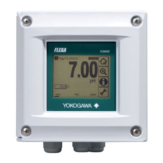
YOKOGAWA FLXA202 User Manual
2-wire analyzer
safety precautions
Hide thumbs
Also See for FLXA202:
- User manual (136 pages) ,
- Technical information (24 pages) ,
- Startup manual (35 pages)

Subscribe to Our Youtube Channel
Related Manuals for YOKOGAWA FLXA202


Summary of Contents for YOKOGAWA FLXA202
- Page 1 User’s Manual Model FLXA202 / FLXA21 2-Wire Analyzer Safety Precautions IM 12A01A02-20E IM 12A01A02-20E 4th Edition...
- Page 2 Safety Precautions n Safety, Protection, and Modification of the Product • In order to protect the system controlled by the product and the product itself and ensure safe operation, observe the safety precautions described in this user’s manual. We assume no liability for safety if users fail to observe these instructions when operating the product. • If this instrument is used in a manner not specified in this user’s manual, the protection provided by this instrument may be impaired. • If any protection or safety circuit is required for the system controlled by the product or for the product itself, prepare it separately. • Be sure to use the spare parts approved by Yokogawa Electric Corporation (hereafter simply referred to as YOKOGAWA) when replacing parts or consumables. • Modification of the product is strictly prohibited. • The following safety symbols are used on the product as well as in this manual. WARNING This symbol indicates that an operator must follow the instructions laid out in this manual in order to avoid the risks, for the human body, of injury, electric shock, or fatalities. The manual describes what special care the operator must take to avoid such risks. CAUTION This symbol indicates that the operator must refer to the instructions in this manual in order to prevent the instrument (hardware) or software from being damaged, or a system failure from occurring. CAUTION This symbol gives information essential for understanding the operations and functions. NOTE This symbol indicates information that complements the present topic. This symbol indicates Protective Ground Terminal. This symbol indicates Function Ground Terminal. Do not use this terminal as the protective ground terminal. Warning and Disclaimer The product is provided on an “as is” basis. YOKOGAWA shall have neither liability nor responsibility to any person or entity with respect to any direct or indirect loss or damage arising from using the product or any defect of the product that YOKOGAWA can not predict in advance.
- Page 3 Mark position of intrinsic safety The mark position of intrinsic safety is shown as follows FLXA202-D-*-… Type:-CB *1: This marking conforms to Intrinsic safety of IECEx. *2: This marking conforms to Intrinsic safety of ATEX. IM 12A01A02-20E 4th Edition : Oct. 01, 2015-00...
-
Page 4: Bottom Side
FLXA21-D-*-… -P (Plastic) -S (Stainless steel) -U (Stainless steel + urethane coating) -E (Stainless steel + epoxy coating) *1: This marking conforms to Intrinsic safety of IECEx. *2: This marking conforms to Intrinsic safety of ATEX. *3: This marking conforms to Intrinsic safety of NEPSI. *4: This marking conforms to Intrinsic safety of FM. *5: This marking conforms to Intrinsic safety of CSA. *6: This marking conforms to nonincendive of FM. *7: This marking conforms to nonincendive of CSA. Top Side Bottom Side *1: This marking conforms to Intrinsic safety of IECEx. *2: This marking conforms to Intrinsic safety of ATEX. *3: This marking conforms to Intrinsic safety of NEPSI. - Page 5 Regulatory Compliance FLXA202/FLXA21 common Compliance Safety: UL 61010-1 UL 61010-2-030 CAN/CSA-C22.2 No.61010-1 CAN/CSA-C22.2 No.61010-2-030 EMC: EN61326-1 Class A, Table 2 (For use in industrial locations) Influence of immunity environment (Criteria A): Output shift is specified within ± 25% of F.S. EN61326-2-3 AS/NZS CISPR11 Korea Electromagnetic Conformity Standard Class A 한국 전자파적합성 기준 A급 기기 (업무용 방송통신기자재) 이 기기는 업무용(A급) 전자파적합기기로서 판매자 또는 사용자는 이 점을 주의하시기 바라며, 가정외의 지역에서 사용하는 것을 목적으로 합니다. Installation altitude:...
- Page 6 ATEX and IECEx Control Drawing (for 4–20mA Type) Hazardous Area Non-hazardous Area FLXA21/FLXA202 Analyzer Housing Assembly Supply Sensor 1 Measuring module 1 Associated Apparatus Supply Sensor 2 Measuring module 2 Supply +, Supply – Ui: 30 V Ii: 100 mA Pi: 0.75 W...
- Page 7 FLXA21 Intrinsic safety and nonincendive (suffix code Type : -EA, -ES): ATEX Intrinsic safety approval Applicable standard Explosive Atmospheres EN 60079-0: 2012/A11: 2013 Equipment - General requirements EN 60079-11: 2012 Equipment protection by Intrinsic safety “i” EN 60079-26: 2007 Equipment with equipment protection level (EPL) Ga EN 60529: 1992 Degrees of protectionprovided by enclosures (IP Code) Type of protection II 1G Ex ia IIC Ga Group: II Category: 1G T4: for ambient temperature:–20 to 55ºC T6: for ambient temperature:–20 to 40ºC (excluding SENCOM module) Atmosphere pressure: 80 kPa (0.8 bar) to 110 kPa (1.1 bar) Degree of Protection of the Enclosure: IP66 IECEx Intrinsic safety approval Applicable standard IEC 60079-0:2011 Part 0: Equipment - General requirements IEC 60079-11: 2011 Part 11: Equipment protection by intrinsic safety “i” IEC 60079-26: 2006 Part 26: Equipment with equipment protection level (EPL) Ga IEC 60529: 2001 Degrees of protection provided by enclosures (IP Code) Type of protection Ex ia IIC Ga T4: for ambient temperature:–20 to 55ºC T6: for ambient temperature:–20 to 40ºC (excluding SENCOM module) Atmosphere pressure: 80 kPa (0.8 bar) to 110 kPa (1.1 bar) Degree of Protection of the Enclosure: IP66 FM Intrinsic safety and nonincendive approval Applicable standard FM-3600: 2011 Approval Standard for Electric Equipment for use in Hazardous (Classified) Locations General Requirement FM-3610: 2010 Approval Standard for Intrinsically Safe Apparatus and Associated Apparatus for Use in Class I, II, and III, Division 1, Hazardous...
- Page 8 C22.2 No213-M1987 Non-incendive Electrical Equipment for Use in Class I, Division 2 Hazardous Locations CAN/CSA-E60079-0-07 Electrical apparatus for explosive gas atmospheres - Part 0: General requirements CAN/CSA-E60079-11-02 Electrical apparatus for explosive gas atmospheres - Part 11: Intrinsic safety “i” IEC 60529:2001 Degrees of protection provided by enclosures (IP Code) Type of protection (C22.2) Class I, Division 1, Groups A, B, C and D (Intrinsically Safe) Class I, Division 2, Groups A, B, C and D (Nonincendive) For all protection type, T4: for ambient temperature: -20 to 55°C T6: for ambient temperature: -20 to 40°C Atmosphere pressure: 80 kPa (0.8 bar) to 110 kPa (1.1 bar) Ambient Humidity: 0 to 100% (No condensation) Degree of Protection of the Enclosure: Type 4X Type of protection (E60079) Ex ia IIC T4: for ambient temperature: -20 to 55°C T6: for ambient temperature: -20 to 40°C Atmosphere pressure: 80 kPa (0.8 bar) to 110 kPa (1.1 bar) Ambient Humidity: 0 to 100% (No condensation) Degree of Protection of the Enclosure: IP66 NEPSI Intrinsic safety approval Applicable standard GB 3836.1-2010 Explosive atmospheres-Part 1: Equipment - General requirements GB 3836.4-2010 Explosive atmospheres-Part 4: Equipment protection by intrinsic safety “i” GB 3836.20-2010 Explosive atmospheres-Part 20: Equipment with equipment protection level (EPL) Ga Type of protection Ex ia IIC Ga T4: for ambient temperature: -20°C to 55°C T6: for ambient temperature: -20°C to 40°C Atmosphere pressure: 80kPa (0.8bar) to 110 kPa (1.1bar) Degree of Protection of the Enclosure: IP66 Electrical Parameters (Ex ia) Each housing assembly (base module) and each sensor module are respectively certificated.
- Page 9 pH/ORP Sensor module, SC Sensor module and DO Sensor module Input parameters Ui, Vmax = 13.92 V Ii, Imax = 50 mA Pi, Pmax = 0.374 W = 40 nF Li = 2.9 mH Output parameters Sensor input circuit(pH: terminals 11 through 19, SC: terminals 11 through 16, DO: terminals 11 through Uo Vt, Voc = 11.76 V Io, It, Isc = 116.5 mA = 0.342 W Co, Ca = 100 nF Lo, La = 1.7mH ISC Sensor module Input parameters Ui, Vmax = 13.92 V Ii, Imax = 50 mA Pi, Pmax = 0.374 W = 40 nF...
- Page 10 ATEX and IECEx Control Drawing (for 4-20mA type) Hazardous Location ← → Non Hazardous Location Measuring module 1 Supply + Sensor 1 Safety Barrier Housing Assembly (Note 1) Supply - Measuring module 2 Sensor 2 Note: The measuring module on this drawing means the sensor module on this General Specifications.
- Page 11 Sensor Input Circuit Type of Measuring Module pH, SC and DO Maximum Voltage (Uo) 11.76 V 11.76 V Maximum Current (Io) 116.5 mA 60.6 mA Maximum Power (Po) 0.3424 W 0.178 W External Capacitance (Ca, Co) 100 nF 100 nF External Inductance (La, Lo) 1.7 mH 8 mH Note 1: In any safety barrier used, the output current must be limited by a resistor “R” such that Imaxout=Uz/R. Note 2: The safety barrier shall be FM Entity-Approved associated apparatus / barrier where : Barrier Voc, Uo ≤ 30V; Barrier Isc, Io ≤ 100 mA; Barrier Po ≤ 0.75W; Barrier Ca, Co ≥ 13 nF+Ccable; Barrier La, Lo ≥ Lcable Note 3: When using non isolation barrier connect (*1) to IS earthing system. Note 4: pH and SC Sensor(s) are of a passive type to be regarded as ‘simple apparatus’ same as 06ATEX0218X, 06ATEX0219, IECEx KEM 06.0052X, FM3028779, 06ATEX0220X, 06ATEX0221, IECEx KEM 06.0053X or the one individually certified with relevant parameters. Note 5: ISC Sensor(s) are ISC40S of 00ATEX1067X or the one individually certified with relevant parameters. Note 6: DO Sensor(s) are of a passive type to be regarded as ‘simple apparatus’ or the one individually certified with relevant parameters.
- Page 12 Electrical Parameters (Nonincendive) Housing Assembly Supply and output circuit (terminals + and -) Ui(Vmax)=30V, Ci=13nF, Li=0mH Measuring module input circuit (CN2 or CN3 on Back board) Uo(Vt,Voc)=13.65V, Io(It,Isc)=50mA, Co(Ca)=80nF, Lo(La)=7.7mH pH module, SC module and DO module Ui(Vmax)=13.92V, Ci=40nF, Li=2.9mH Sensor input circuit (terminals 11 through 19) Uo(Vt,Voc)=11.76V, Io(It,Isc)=116.5mA, Co(Ca)=4uF, Lo(La)=4.5mH ISC module Ui(Vmax)=13.92V, Ci=40nF, Li=7.7mH Sensor input circuit (terminals 11 through 17) Uo(Vt,Voc)=11.76V, Io(It,Isc)=60.6mA, Co(Ca)=4uF, Lo(La)=19mH Note for Intrinsically Safe Installation: 1: In any safety barrier used, the output current must be limited by a resistor “R” such that Io=Uo/R or Isc=Voc/R. 2: The safety barrier must be CSA certified. 3: Input voltage of the safety barrier must be less than 250Vrms/Vdc 4: When using non isolation barrier connect (*1) to IS earthing system. 5: pH and SC Sensor(s) are of a passive type to be regarded as ‘simple apparatus’ same as 06ATEX0218X, 06ATEX0219, IECEx KEM 06.0052X, FM3028779, 06ATEX0220X, 06ATEX0221, IECEx KEM 06.0053X or the one individually certified with relevant parameters. 6: ISC Sensor(s) are ISC40S of 00ATEX1067X or the one individually certified with relevant parameters. 7: DO Sensor(s) are of a passive type to be regarded as ‘simple apparatus’ or the one individually certified with relevant parameters. 8: Measuring module 2 may not mounted. As for ISC module, only one can be mounted. 9: Installation should be in accordance with Canadian Electrical Code Part I and Local Electrical Code. 10: Do not alter drawing without authorization from CSA. Note for Nonincendive Installation: 1: The parameter for sensor input circuit must be taken into account when installed. 2: Installation should be in accordance with Canadian Electrical Code Part I and Local Electrical Code.
- Page 13 WARNING Installation and wiring The FLXA202/FLXA21 should only be used with equipment that meets the relevant IEC, American or Canadian standards. Yokogawa accepts no responsibility for the misuse of this unit. WARNING Don’t install “general purpose type” instruments in the hazardous area. CAUTION The Instrument is packed carefully with shock absorbing materials, nevertheless, the instrument may be damaged or broken if subjected to strong shock, such as if the instrument is dropped. Handle with care. CAUTION This instrument is a Class A product, and it is designed for use in the industrial environment. Please use this instrument in the industrial environment only. CAUTION When you open the front panel, make sure the screws are completely out of the screw holes, and then open the front panel slowly in order not to damage the threaded parts on the housing. If the threaded parts are damaged and the screws cannot be tightened, the waterproof performance will deteriorate. CAUTION The HART communication may be influenced by strong electromagnetic field. In this case another trial of the HART communication and/or operation with FLXA202/FLXA21 touch screen can be carried out. IM 12A01A02-20E 4th Edition : Oct. 01, 2015-00...
- Page 14 WARNING • Do not use an abrasive or organic solvent in cleaning the instrument. • Substitution of components may impair suitability for Division 2. Do not remove or replace while circuit is live unless area is know to be non hazardous. Explosion Hazard – Do not disconnect equipment unless area is known to be non hazardous. Do not reset circuit breaker unless power has been removed from the equipment or the area is known to be non hazardous. WARNING Electrostatic discharge The FLXA202/FLXA21 contains devices that can be damaged by electrostatic discharge. When servicing this equipment, please observe proper procedures to prevent such damage. Replacement components should be shipped in conductive packaging. Repair work should be done at grounded workstations using grounded soldering irons and wrist straps to avoid electrostatic discharge. CAUTION Be careful to touch the concentrated sulfuric acid. l How to dispose the batteries: This is an explanation about the new EU Battery Directive(DIRECTIVE 2006/66/EC).This directive is only valid in the EU. Batteries are included in this product.Batteries incorporated into this product cannot be removed by yourself.Dispose them together with this product. When you dispose this product in the EU,contact your local Yokogawa Europe B.V.office.Do not dispose them as domestic household waste. Battery type: Manganese dioxide lithium battery Notice: The symbol means they shall be sorted out and collected as ordained in ANNEX II in DIRECTIVE 2006/66/EC. l Product Disposal: The instrument should be disposed of in accordance with local and national legislation/regulations. IM 12A01A02-20E 4th Edition : Oct. 01, 2015-00...
- Page 15 For Intrinsic safety type WARNING Electrostatic charge may cause an explosion hazard. Avoid any actions that cause the generation of electrostatic charge, e.g., rubbing with a dry cloth. Because the enclosure of the FLXA21 2-Wire Analyzer, if it is mounted in an area where the use of category 1 G Zone 0 apparatus is required, it must be installed such, that, even in the event of rare incidents, ignition sources due to friction sparks are excluded. Figure 1 Warning label Warranty and service Yokogawa products and parts are guaranteed free from defects in workmanship and material under normal use and service for a period of (typically) 12 months from the date of shipment from the manufacturer. Individual sales organisations can deviate from the typical warranty period, and the conditions of sale relating to the original purchase order should be consulted. Damage caused by wear and tear, inadequate maintenance, corrosion, or by the effects of chemical processes are excluded from this warranty coverage. In the event of warranty claim, the defective goods should be sent (freight paid) to the service department of the relevant sales organisation for repair or replacement (at Yokogawa discretion). The following information must be included in the letter accompanying the returned goods: • Part number, model code and serial number • Original purchase order and date • Length of time in service and a description of the process • Description of the fault, and the circumstances of failure • Process/environmental conditions that may be related to the failure of the device. • A statement whether warranty or nonwarranty service is requested • Complete shipping and billing instructions for return of material, plus the name and phone number of a contact person who can be reached for further information.
- Page 16 The Authorised Representative for this product in EEA is Yokogawa Europe B.V. (Euroweg 2, 3825 HD Amersfoort, The Netherlands). n Copyright and Trademark Notices The copyrights of online manual contained in the CD-ROM are reserved. The online manual is protected by the PDF security from modification, however, it can be output via a printer. Printing out the online manual is only allowed for the purpose of using the product. When using the printed information of the online manual, check if the version is the most recent one by referring to the CD-ROM’s version. No part of the online manual may be transferred, sold, distributed (including delivery via a commercial PC network or the like), or registered or recorded on video tapes. FLEXA, FLXA and SENCOM are registered trademarks of Yokogawa Electric Corporation. Adobe, Acrobat and Acrobat Reader are either registered trademarks or trademarks of Adobe Systems Incorporated in the United States and/or other countries. All other company and product names mentioned in this user’s manual are trademarks or registered trademarks of their respective companies. We do not use TM or ® mark to indicate those trademarks or registered trademarks in this user’s manual. FLXA202/FLXA21’s fonts (c) Copyright 2000-2001 /efont/ The Electronic Font Open Laboratory. All rights reserved. Redistribution and use in source and binary forms, with or without modification, are permitted provided that the following conditions are met: 1. Redistributions of source code must retain the above copyright notice, this list of conditions and the following disclaimer. 2. Redistributions in binary form must reproduce the above copyright notice, this list of conditions and the following disclaimer in the documentation and/or other materials provided with the distribution. 3. Neither the name of the team nor the names of its contributors may be used to endorse or promote products derived from this font without specific prior written permission. THIS FONT IS PROVIDED BY THE TEAM AND CONTRIBUTORS “AS IS” AND ANY EXPRESS OR IMPLIED WARRANTIES, INCLUDING, BUT NOT LIMITED TO, THE IMPLIED WARRANTIES OF MERCHANTABILITY AND FITNESS FOR A PARTICULAR PURPOSE ARE DISCLAIMED. IN NO EVENT SHALL THE TEAM OR CONTRIBUTORS BE LIABLE FOR ANY DIRECT, INDIRECT, INCIDENTAL, SPECIAL, EXEMPLARY, OR CONSEQUENTIAL DAMAGES (INCLUDING, BUT NOT LIMITED TO, PROCUREMENT OF SUBSTITUTE GOODS OR SERVICES; LOSS OF USE, DATA, OR PROFITS; OR BUSINESS INTERRUPTION)
- Page 17 Blank Page...
- Page 18 Revision Record l Manual Title : Model FLXA202 / FLXA21 2-Wire Analyzer Safety Precautions l Manual No. : IM 12A01A02-20E Oct. 2015/4th Edition Addition of FLXA202. Regulatory Compliance (P.4) Apr. 2015/3rd Edition Regulatory Compliance (P.4) Oct. 2014/2nd Edition Addition of NEPSI and ATEX/IECEx (SENCOM module). Sep. 2013/1st Edition Newly published IM 12A01A02-20E 4th Edition : Oct. 01, 2015-00...
- Page 19 Blank Page...
- Page 20 Though User’s Manual, IM 12A01A02-20E 4th Edition, is provided with the product, an addition to the manual has been made. Please use the following contents after a reading before using the FLXA202/FLXA21. Note Change and addition of the mark position ...
- Page 21 (page 3) replacement FLXA21-D-*-… (Output: -A) -P (Plastic) -S (Stainless steel) Type:-CB Type:-CD -U (Stainless steel + urethane coating) Type:-DD Type:-CH -E (Stainless steel + epoxy coating) -W (Stainless steel + high anti-corrosion coating) Type:-CB Type:-CD Type:-EG Type:-DD Type:-CH *1: This marking conforms to Intrinsic safety of IECEx. *2: This marking conforms to Intrinsic safety of ATEX.
- Page 22 FLXA21-D-*-… (Output: -F, -P) -F (FOUNDATION Fieldbus) Type: -CB Type: -CD Type: -DD Type: -CH -P (PROFIBUS PA) Type: -CB Type: -CD Type: -DD Type: -CH -F (FOUNDATION Fieldbus) -P (PROFIBUS PA) Type: -EG Type: -EG *1: This marking conforms to Intrinsic safety of IECEx. *2: This marking conforms to Intrinsic safety of ATEX.
- Page 23 EN61326-2-5 (suffix code Output : -F, -P) AS/NZS CISPR11 RCM: EN 55011 Class A, Group 1 Korea Electromagnetic Conformity Standard Class A RoHS: EN 50581: 2012 (FLXA202; Style 1.02 or newer, FLXA21; Style 3.03 or newer) IM 12A01A02-20E 4/23 4th Edition...
- Page 24 (page 4) change and FLXA21 FLXA202 Intrinsic safety and nonincendive (suffix code Type : -CB, -CD, -DD, -CH, -CG (FLXA202), -EG (FLXA21)): ATEX Intrinsic safety approval Applicable standard Explosive Atmospheres EN 60079-0:2012+A11: 2013 Equipment - General requirements EN 60079-11:2012 Equipment protection by Intrinsic safety “i”...
- Page 25 ⁞ Specific Conditions of Use - When the enclosure of the Analyzer is made of aluminum alloy (FLXA202), and when the Analyzer used in an explosive atmosphere requiring equipment of Category 1 G or EPL Ga, it must be installed in such a way that, even in the event of rare incidents, an ignition source due to impact friction sparks is excluded.
- Page 26 IM 12A01A02-20E 7/23 4th Edition...
- Page 27 IM 12A01A02-20E 8/23 4th Edition...
- Page 28 IM 12A01A02-20E 9/23 4th Edition...
- Page 29 IM 12A01A02-20E 10/23 4th Edition...
- Page 30 (pages 6 to 11) delete and addition FLXA21 ATEX and IECEx Control Drawing (FOUNDATION Fieldbus / PROFIBUS PA Type) Hazardous Area Non-hazardous Area FLXA21 Series Analyzer Other Housing Assembly Field Devices Supply Sensor 1 Associated Apparatus Measuring Module 1 •• Supply Terminators Supply +, Supply –...
- Page 31 IM 12A01A02-20E 12/23 4th Edition...
- Page 32 IM 12A01A02-20E 13/23 4th Edition...
- Page 33 IM 12A01A02-20E 14/23 4th Edition...
- Page 34 IM 12A01A02-20E 15/23 4th Edition...
- Page 35 (page 6) addition FLXA202 Type n (suffix code Type : -DB, -DE): ATEX Type n approval Applicable standard EN 60079-0:2012/A11:2013 Equipment – General requirements EN 60079-11:2012 Equipment protection by Intrinsic safety “i” EN 60079-15:2010 Equipment protection by type of protection “n”...
- Page 36 ATEX Type n IM 12A01A02-20E 17/23 4th Edition...
- Page 37 IECEX Type n IM 12A01A02-20E 18/23 4th Edition...
- Page 38 IM 12A01A02-20E 19/23 4th Edition...
- Page 39 IM 12A01A02-20E 20/23 4th Edition...
- Page 40 IM 12A01A02-20E 21/23 4th Edition...
- Page 41 IM 12A01A02-20E 22/23 4th Edition...
- Page 42 IM 12A01A02-20E 23/23 4th Edition...
Need help?
Do you have a question about the FLXA202 and is the answer not in the manual?
Questions and answers