
Subscribe to Our Youtube Channel
Related Manuals for YOKOGAWA FLXA402T


Summary of Contents for YOKOGAWA FLXA402T
- Page 1 User’s Manual FLXA402T Liquid Analyzer for Turbidity and Chlorine Installation and Wiring (Introduction and General Description) IM 12A01G01-02EN IM 12A01G01-02EN 1st Edition...
-
Page 2: Introduction
Thank you for purchasing the FLXA 402T Liquid Analyzer for Turbidity and Chlorine. This User’s Manual contains all essential information for the user to make full use of FLXA402T. Please read the following respective documents before installing and using the FLXA402T. - Page 3 • No part of the user’s manuals may be transferred or reproduced without prior written consent from YOKOGAWA. • YOKOGAWA reserves the right to make improvements in the user’s manuals and product at any time, without notice or obligation. • If you have any questions, or you find mistakes or omissions in the user’s manuals, please contact our sales representative or your local distributor.
-
Page 4: Table Of Contents
Toc-1 FLXA402T Liquid Analyzer for Turbidity and Chlorine Installation and Wiring (Introduction and General Description) IM 12A01G01-02EN 1st Edition CONTENTS Introduction ....................i INTRODUCTION AND GENERAL DESCRIPTION ........1-1 Instrument check ....................1-2 Name and description ..................1-6 Specification ...................... 1-8 Model &... - Page 5 Blank Page...
-
Page 6: Introduction And General Description
The FLXA402T works with pH, conductivity sensors in addition to turbidity or residual chlorine sensors. For the transfer of diagnostic data and other device information to a host system, the FLXA402T supports MODBUS RTU/RS485 protocols. The FLXA402T also provides local display using RS- 485 or Ethernet. -
Page 7: Instrument Check
Upon delivery, unpack the instrument carefully and inspect it to ensure that it was not damaged during shipment. If damage is found, retain the original packing materials (including the outer box) and then immediately notify the carrier and the relevant Yokogawa sales office. Checking the model and suffix code Make sure the model and suffix code on the nameplate affixed to the left side of the housing. - Page 8 <1. INTRODUCTION AND GENERAL DESCRIPTION> Spare parts Spare parts are supplied by Yokogawa with the product. Make sure items in Table 1.1 are included. Table 1.1 Spare parts Product Name Model and suffix code Quantity Remark All others except the one Cable gland (M20x1.5): 8 pcs...
- Page 9 <1. INTRODUCTION AND GENERAL DESCRIPTION> Table 1.2 Options (option code) Product Name Model and Quantity Remark suffix code Pipe and wall mounting Option code: / 1 set For /UM, bracket for /U hardware UM, /U and /PM,one of each, are supplied. Panel mounting Option code: 1 set...
- Page 10 <1. INTRODUCTION AND GENERAL DESCRIPTION> Product Name Model and Quantity Remark suffix code Conduit adapter Option code: Adapter: 4 pcs /CB4, /CD4, / Cable gland for adapter: 4 pcs Rubber plug attachment : 1 piece Adapter: 3 pcs /CB6, /CD6, / Cable gland for adapter: 3 pcs Ethernet adapter: 1 piece Ethernet cable gland (black): 1 piece...
-
Page 11: Name And Description
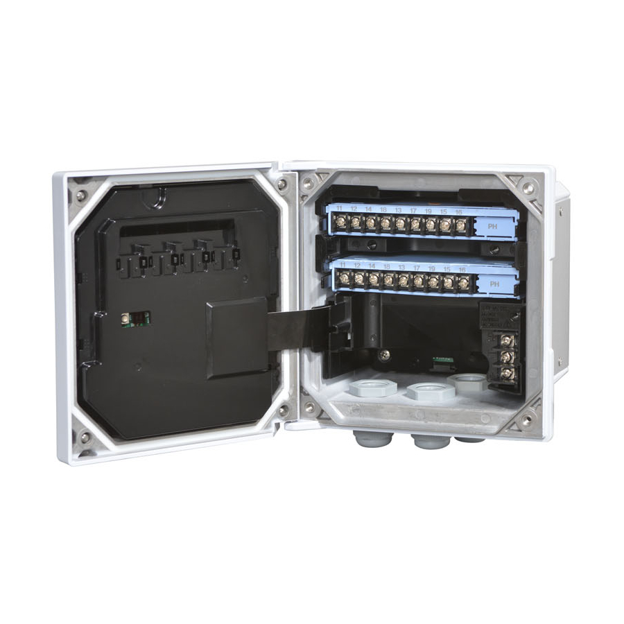
(Do not use it) Front view Front view with the front panel opened Figure 1.2 FLXA402T Parts names and descriptions CAUTION Do not switch ON the Slide switch 1 or 2. Do not press reboot switch, either. IM 12A01G01-02EN 1st Edition : Mar. 25, 2021-00... - Page 12 <1. INTRODUCTION AND GENERAL DESCRIPTION> FLXA402T is a module-designed converter, assigning each function to respective module. The figure below shows how modules are installed, although modules to use are different according to specification. IO module 1st sensor module 2nd sensor module...
-
Page 13: Specification
<1. INTRODUCTION AND GENERAL DESCRIPTION> Jumper and Jumper holder When you don’t need the jumpers, store them in the jumper holders located inside of the front panel, to prevent them from being lost. You can put jumpers anywhere among 5 holders (1A and 4Bs) as Figure 1.4. A has a guide hole. -
Page 14: Model & Suffix Codes
<1. INTRODUCTION AND GENERAL DESCRIPTION> Model & Suffix Codes Model Suffix code Option code Description FLXA402T ······································································· ················· Liquid Analyzer for Turbidity and Chlorine Power ················· AC version supply Housing ················· Aluminum alloy cast + urethane coating ················· Aluminum alloy cast + high anti-corrosion... -
Page 15: Dimensions
1-10 <1. INTRODUCTION AND GENERAL DESCRIPTION> Conduit adapter (need to be purchased additionally) Parts Type Quantity Remark number G 1/2 K9703WF 4 set for Option code /CB□ (Cable gland for adapter + adapter) 1/2 NPT K9703WG 4set for Option code /CD□ (Cable gland for adapter + adapter) M 20 x 1.5 K9703WH... -
Page 16: Wiring And Installation
<2. WIRING AND INSTALLATION> WIRING AND INSTALLATION Install the cable glands on FLXA402T before wiring. The cable glands are included inside the product package. Installation site The FLXA402T is weatherproof and can be installed both indoors and outdoors. It should, however, be installed as close as possible to the sensor to avoid long cable runs between the instrument and sensor. -
Page 17: Mounting Methods
<2. WIRING AND INSTALLATION> Mounting methods See 1.5 Dimensions for information on the hardware for mounting. The FLXA402T has various mounting possibilities.(Figure.2.1) • Panel mounting using optional mounting hardware (/PM or /UM) • Wall mounting using optional mounting hardware (/U or /UM) •... -
Page 18: Removing The Shield Cover
<2. WIRING AND INSTALLATION> Removing the shield cover The shield cover covers high-voltage power supply terminals and relay modules. CAUTION To ensure your safety, be sure to shut down the power supply before you remove the shield cover. Open the front panel and remove the shield cover. After removing the shield cover, install the cable glands. -
Page 19: Installing The Cable Glands
<2. WIRING AND INSTALLATION> Installing the cable glands The supplied cable glands are for cables with an outside diameter of 6 to 12 mm (0.24 to 0.47 inches). Unused cable entry holes must be sealed with cable glands including the supplied rubber close up plugs. - Page 20 <2. WIRING AND INSTALLATION> Conduit adapter When protecting the cable with a conduit, use an adapter. (option codes: /CB4, /CD4, /CF4, /CB6, /CD6 /, /CF6) CAUTION There are 8 holes for cable connection. Apply the cable gland of supplied accessories (dark- grayed cable glands) to the holes which no conduit adapters connect to.
-
Page 21: Wiring
FLXA402T and the connected device on the other side. If there is no potential difference between the FLXA402T and the device on the other side, it may be more effective to connect to the ground on both sides. -
Page 22: Wiring The Power Supply Terminal Unit
CAUTION Make sure the power supply is switched off before wiring. Power rating must comply with FLXA402T specification. Power voltage must match with the one indicated on the name plate. WARNING ● You must install external power supply switch or circuit breaker for power supply. - Page 23 Connecting AC power supply Grounding CAUTION Connect FLXA402T to ground. (Class D ground: 100 ohm or less) for interference avoidance and safety reasons. Use ground cables with larger cross - sectional area. Connect the grounding cable to the terminal of the power module inside. See Figure 2.8.
-
Page 24: Wiring Relay Module (Contact Outputs)
S4(NC) Contact S4 Normally Close Figure 2.9 Relay module contacts FLXA402T has 4 contact outputs, which allows configuration to adjust to operation. Contact S4 is fail safe contact. See IM-Converter operation Section 4.4. IM 12A01G01-03EN There are 2 cable inlets. Take a suitable one to run wiring with good structure. Be sure to plug unused cable gland with a supplied rubber close up plug. -
Page 25: Wiring Network Cables
<2. WIRING AND INSTALLATION> 2.5.3 Wiring network cables FLXA402T provides two types of wired digital network, Ethernet (Modbus TCP/IP) or RS-485 (Modbus RTU). Use shielded cable to avoid deteriorated performance caused by EMI disturbance or radiation effects on electric devices. -
Page 26: Wiring Io Module
Wiring mA output FLXA402T transmits 4-20 mA analog signals with maximum load of 600 Ω to peripherals including a control system or recorders. IO module has mA output function. Be sure to use shielded cables for output signal cables, and connect shield to terminal 63 (or 89*). - Page 27 IO code -A4 is selected Figure 2.15 IO module terminal assignment When all wiring is complete, close the FLXA402T front cover, and turn the power on. Check that the screen displays normally. CAUTION To install the front panel, tighten each screw evenly until every four of them is completely fastened.
-
Page 28: Sensor Wiring
2-13 <2. WIRING AND INSTALLATION> Sensor wiring The FLXA402T can be used with a wide range of commercially available sensor types, both from Yokogawa and other manufacturers. Terminal screw size is M3, and torque of screw up is 0.6 N•m. -
Page 29: Wiring Chlorine Meter, Turbidity Meter
RC800D Figure 2.30 Wiring SENCOM SA Wire a dedicated cable for the turbidimeter or chlorine meter to connect to FLXA402T. Because the dedicated cables are thin, first remove the cable gland’s standard packing and apply the supplied grommet instead. Grommet Remove the standard packing. -
Page 30: Wiring The Ph Sensor
2-15 <2. WIRING AND INSTALLATION> 2.6.2 Wiring the pH sensor pH Measurement Conventional pH sensors are connected to the module as follows: FLXA402 11 Temperature 12 Temperature 13 Reference 14 Solution ground 15 Glass (measure) 16 Shield 17 Shield Liquid Earth In addition to the wiring of the sensor, ensure that a jumper for low-impedance sensor inputs is installed. -
Page 31: Wiring The Conductivity (Sc) Sensor
2-16 <2. WIRING AND INSTALLATION> 2.6.3 Wiring the conductivity (SC) sensor Contacting Conductivity, SC, sensors are connected to the module as follows: FLXA402 Temp The above diagram shows wiring for 4-electrode conductivity sensors, such as SC42-SP34 large bore series. For 2-electrode conductivity sensors, such as SC42-SP36 small bore series, jumpers must be installed between terminals 13-14 and between terminals 15-16, as shown in the diagram below. -
Page 32: Customer Maintenance Parts List
K9703ZL Screw set (for panel mount), 2 pcs A1633EF Fuse K9703SS Pipe and wall mounting set (option code: /U) CMPL 12A01G01-01EN All Rights Reserved. Copyright © 2021 Yokogawa Electric Corporation. Subject to change without notice. 1st Edition: Mar. 2021 (YK) - Page 33 Table 1 Item 16; Sensor module assembly, QIC sheet is included. Type code -AB, -AD, -AG, -AJ Module K9704EB K9704FB SENCOM SA K9704SB Note: The part numbers in Table 1 are modules with QIC. Sensor module number in the Table 2 shows each model number printed on the QIC.
-
Page 34: Revision Record
Revision Record Manual Title : FLXA402T Liquid Analyzer for Turbidity and Chlorine, Installation and Wiring (Introduction and General Description) Manual No. : IM 12A01G01-02EN Mar. 2021/1st Edition Newly released Yokogawa Electric Corporation 2-9-32 Nakacho, Musashino-shi, Tokyo 180-8750, JAPAN http://www.yokogawa.com/ IM 12A01G01-02EN... - Page 35 Blank Page...
Need help?
Do you have a question about the FLXA402T and is the answer not in the manual?
Questions and answers