
Related Manuals for SMC Networks HEC002-A5


Summary of Contents for SMC Networks HEC002-A5
- Page 1 A_HEC-OM-I009 Rev1.6 Apr.2018 サーモコン HEC002-A Air-cooled Thermo-con Model No. HEC002-A5* HEC006-A5* Keep this manual available at all times.
- Page 3 History History Version Preface Contents Chap.1 Chap.2 Chap.3 Chap.4 Chap.5 Version Chap.6 Chap.7 Chap.8 Chap.9 Chap.10 Record of Changes Version Contents Date First edition Sep.2005 1.2: Change the address of R&D Center. 4.1: Add model option. Jul.26.2006 6.1: Change Accuracy related to temp(stability) Add HEC006-A May.20.2008 Add caution of the heavy object.
- Page 4 Preface Preface Thank you very much for purchasing SMC Thermo-con. (herein referred to as the “product”). This manual is describes the operation of the product. Please use this manual for efficient and long use of this unit. Be sure to read this manual efficiently for your deep understanding of overview and safety of this unit before installation or carrying out the relevant operations of this unit.
-
Page 5: Table Of Contents
Contents Contents Page Introduction ----------------------------------------------------------------------------- 1-1 1.1 Scope and general description of use -------------------------------------------------------------- 1-1 1.2 Operation by external communication -------------------------------------------------------------- 1-1 1.3 Contents of operation manual ------------------------------------------------------------------------ 1-2 Safety Instructions ------------------------------------------------------------------- 2-1 2.1 Before using the Thermo-con ------------------------------------------------------------------------- 2-1 2.1.1 Safety training ----------------------------------------------------------------------------------------------------------- 2-1 2.1.2 Identification of “Danger”, “Warning”, “Caution”... - Page 6 Contents 4.6.7 Upper/Lower temperature limit alarm function ------------------------------------------------------------------ 4-7 Names and Functions of Components ---------------------------------------- 5-1 5.1 Side view ---------------------------------------------------------------------------------------------------- 5-1 5.1.1 HEC002 ------------------------------------------------------------------------------------------------------------------ 5-1 5.1.2 HEC006 ------------------------------------------------------------------------------------------------------------------ 5-1 5.1.3 Air Filter ------------------------------------------------------------------------------------------------------------------ 5-2 5.2 Top view ----------------------------------------------------------------------------------------------------- 5-2 5.2.1 Operation panel -------------------------------------------------------------------------------------------------------- 5-3 5.2.2 Display -------------------------------------------------------------------------------------------------------------------- 5-3 5.2.3 Reservoir Cap ---------------------------------------------------------------------------------------------------------- 5-4 5.3 Auto tuning function -------------------------------------------------------------------------------------- 5-4...
- Page 7 Contents 8.5 Setting mode, Level 3 ----------------------------------------------------------------------------------- 8-5 8.5.1 How to enter and return ----------------------------------------------------------------------------------------------- 8-5 8.5.2 Available mode in Level 3 -------------------------------------------------------------------------------------------- 8-5 8.6 Detail of setting mode level ---------------------------------------------------------------------------- 8-6 8.6.1 Setting mode, Level 1 ------------------------------------------------------------------------------------------------- 8-6 8.6.2 Setting mode, Level 2 ------------------------------------------------------------------------------------------------- 8-8 8.6.3 Setting mode, Level 3 ----------------------------------------------------------------------------------------------- 8-10 Alarm -------------------------------------------------------------------------------------- 9-1 9.1 How to Identify Alarm ----------------------------------------------------------------------------------- 9-1...
- Page 8 Contents Table List Page Table 2-1 Division of DANGER, WARNING, CAUTION, and NOTE ------------------------------------------------------- 2-2 Table 2-2 Meaning of a symbol ----------------------------------------------------------------------------------------------------- 2-2 Table 2-3 Safety interlock list(Part 1) ---------------------------------------------------------------------------------------------- 2-5 Table 2-4 Safety interlock list(Part 2) ---------------------------------------------------------------------------------------------- 2-5 Table 6-1 Specifications -------------------------------------------------------------------------------------------------------------- 6-1 Table 8-1 Available mode in Level 1 ----------------------------------------------------------------------------------------------- 8-2 Table 8-2 Available mode in Level 2 ----------------------------------------------------------------------------------------------- 8-4 Table 8-3 Available mode in Level 3 ----------------------------------------------------------------------------------------------- 8-5...
-
Page 9: Introduction
Introduction Introduction The definition and construction of operation manual are described below. 1.1 Scope and general description of use The operation manual applies to operation method of SMC-brand Thermo-con HEC002-A and HEC006- A. Thermo-con is air-to-liquid heat exchanger to be used to control the temperature (e.g. detectors in an X-Ray system). -
Page 10: Contents Of Operation Manual
Introduction 1.3 Contents of operation manual 1) Chap. 1 Introduction The definition and use of operation manual are described. 2) Chap. 2 Safety Instructions Safety instruction, caution note, danger and warning, warning label and caution label and safety interlock used in this unit are described. 3) Chap.3 Caution on Installation The precautions for setting up and mounting this unit are described. -
Page 11: Safety Instructions
Safety Instructions Safety Instructions 2.1 Before using the Thermo-con This chapter is dedicated for your safety during interaction with the product. The product is operated at high voltage. Therefore, not only those who operate the unit, but those who are in charge of service and who work nearby the product should read carefully and thoroughly understand descriptions related to safety in this manual before starting the work. - Page 12 Safety Instructions Table2-1 Division of DANGER, WARNING, CAUTION, and NOTE These paragraphs highlight hazards that would cause serious or even fatal injuries to workers if handled improperly or important instructions are ignored. DANGER These paragraphs highlights hazards that might cause serious injuries to workers if the appropriate procedure is not carried out or warnings are ignored.
-
Page 13: Warning" Label And "Caution" Label
Safety Instructions 2.2 “Warning” label and “Caution” label This product is provided with “Warning” labels and “Caution” labels to inform the operator of hazards related to the product. Check the contents and position of all labels before starting the work. The product shall be handled only by trained personnel only. -
Page 14: Precautions For Running(Safety Interlock)
Safety Instructions 2.3 Precautions for running (safety interlock) This is a function to protect personnel, to restrict operation, that may cause damage to the product or facility, and to remove dangers related to safety. This unit has several interlock functions, which activate when dangerous operation or condition occurs to stop operation and make it safe. -
Page 15: Interlock List
Safety Instructions 2.3.1 Interlock list Table2-3 Safety interlock list (Part 1) Description Part Quantity Location Cause Overheat in Heat Detects abnormal heat in heat Heat Thermostat Exchanger exchanger. Exchanger Switching Power supply Detects abnormal current, voltage or power supply Thermostat heat. -
Page 16: Disposing Of Product
Safety Instructions Detection of Shuts off power supply to Error indication on display. Restart power breakage of temp. the Heat exchanger, Pump supply (ERR17) sensor and Fan. Shuts off power supply to Error indication on display. Excessive temp. Restart power the Heat exchanger, Pump increase supply... -
Page 17: Caution On Installation
Caution on Installation Caution on Installation Pay special attention to the safety of all personnel when installing and transporting the product. The product is heavy, be careful when installing or moving the product. Only trained personnel can perform work such as installation, transportation and maintenance of the product. -
Page 18: Installation
Caution on Installation 3.2 Installation If the air inlet of Thermo-con and the outlet opening is not enough, the cooling capacity decreases due to the rise of the ambient temperature, decrease of the radiating air flow. Install Thermo-con following condition. Moreover, when the exhaust duct is necessary, prepare it by customer. Air IN Air OUT HEC002:100mm or more... -
Page 19: Piping
Caution on Installation 240(HEC002) 270(HEC006) 300(HEC002) 280(HEC006) Fig3-3 Mounting Be sure to correctly tighten all screws the required torque. 3.4 Piping Ensure the flow rate of the circulating fluid is as high as possible to maintain the temperature stability. Therefore, the length of the external piping should be minimized and internal diameter should be as large as possible. - Page 20 Caution on Installation HEC002-A/HEC006-A...
-
Page 21: Unit Overview
Unit Overview Unit Overview 4.1 Method of identifying model HEC002 – A 5 B - * Option Cooling capacity With no option 230W With flow switch 600W NPT fitting Radiating method Air-cooled Serial communication RS-485 Power supply RS-232C AC100-240V 4.2 Manufacturing years method of display o -0001 SERIAL No. -
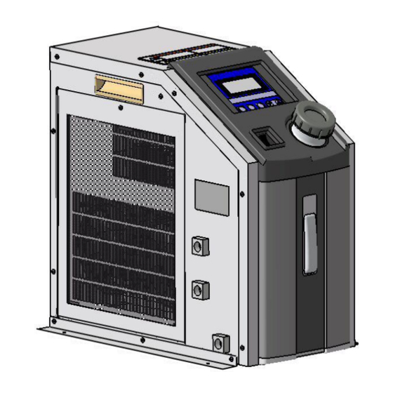
Page 22: Appearance
Unit Overview 4.4 Appearance The appearance and the outline dimensions are as shown below. HEC002-A 240 270 393 385 HEC006-A 270 300 390 382 Fig.4-3 Outside drawings of Thermo-con HEC002-A/HEC006-A... -
Page 23: Outline Of Operation
Unit Overview 4.5 Outline of operation The unit is operated as explained below. 4.5.1 Electrical diagram The unit is equipped with electrical circuits as shown below. Membrane display key sheet Temp. sensor CPU board Level switch Controller RS-485/RS-232C Thermostat Power supply board External sensor Thermo-module... -
Page 24: Functions
Unit Overview 4.6 Functions 4.6.1 Auto tuning This function sets the values necessary for the control system such as PID (proportional band, integral time, derivative time and ratio of cooling/ heating gain) automatically. 4.6.2 Offset function This function controls the temperature slide by an offset value from set point temperature. The range of offset is -9.99 to 9.99 C. -
Page 25: Names And Functions Of Components
Names and Functions of Components 5 Names and Functions of Components The parts included into the unit have description and function individually. 5.1 Side view 5.1.1 HEC002 Handle Power supply connector Handle Communication connector Alarm connector EXT. Sensor Level connector gauge Air filter Circulating fluid... -
Page 26: Air Filter
Names and Functions of Components 5.1.3 Air Filter Air Filter The Thermo-con adopts air-cooled heat exchanger not to allow dust to enter easily inside. However, should the dust be allowed and attached on the filter, the filter may become unable to function properly. To prevent this, the filter should be taken out by removal of circled screws and cleaned periodically. -
Page 27: Operation Panel
Names and Functions of Components 5.2.1 Operation panel RET key SEL key Used to fix set value or Used to change return to present temp. setting mode. status indication. AT key Used to start and stop auto tuning. Up and Down Key Used to change set value in each setting mode. -
Page 28: Reservoir Cap
Names and Functions of Components 5.2.3 Reservoir Cap Reservoir Cap Removed to supply circulating fluid before operation. Replace cap before starting operation. Counter-clockwise to open Clockwise to close. Gasket (Included) Between the reservoir cap and reservoir for sealing. Under a circumstance where a tank get negative pressure, remove the gasket after confirming that the circulating fluid will not flow back when... -
Page 29: Specifications
Specifications Specifications 6.1 Specification table The specifications of the Thermo-con is as shown below. 6-1 Specifications Item Spec. Model No. HEC002-A HEC006-A 10.0 to 60.0 C (No dew condensation) Operation temp. range -9.9 - 80.0 C Indication temp. range Temp. :10 to 35 C Ambient environment Humidity : 35 to 80%RH Environment : No corrosive gas, solvent such as thinner and flammable gas... -
Page 30: Performance Chart
Specifications 6.2 Performance chart Value on performance chart is not guaranteed value but representative value. The value used for consideration should not be the very limit for the safety. 1) Cooling capacity Fluid: water Fluid: water 1400 Ambient 15C 1200 1000 Ambient 15C Ambient 35C... - Page 31 Specifications HEC002-A Fluid: water 0.10 0.08 0.06 0.04 0.02 0.00 Flow rate L/min HEC006-A Fluid: water 0.12 0.10 0.08 0.06 0.04 0.02 0.00 Flow rate L/min Fig. 6-3 Pump capacity HEC002-A/HEC006-A...
- Page 32 Specifications HEC002-A/HEC006-A...
-
Page 33: Preparation For Operation
Preparation for Operation Preparation for Operation 7.1 Preparation for circulating fluid The piping for circulating fluid is connected as below. The piping for circulating fluid is located at the left side face. The same fittings are used for IN and OUT of the circulating fluid. -
Page 34: Power Supply
Preparation for Operation Power supply The power supply shall be connected with attached power supply cable. Confirm the power supply at factory has enough capacity and the voltage is within specified value beforehand (with reference to electrical specifications of the power supply). This unit is provided with the power supply cable. -
Page 35: Check - Repair
Preparation for Operation Operation of the pump with the plenty of air left in the piping for prolonged period may cause the pump to break. Exhaust the air enough from the piping before starting operation of the pump. Take enough care not to spill the feed water over the case when supplying water to the reservoir. -
Page 36: Check After Seismic Vibration And Impact
Preparation for Operation Remove the dust attached to a filter by vacuum cleaner to prevent degrading of performance. The recommended interval of removal is once per 3 months. Do not use water or boiled water since it leads to generation of rust at a frame. 7.5.2 Check after seismic vibration and impact Piping: Confirm there is no defect including disconnection in piping. -
Page 37: Operation
Operation Operation This chapter describes the detailed information on how to operate. 8.1 Condition after power up 1.Indication of software version When power is turned on, software version is S O F T V E S I O N indicated on display panel for approx. 1 sec. 1 . -
Page 38: Setting Mode, Level
Operation 8.3 Setting Mode, Level 1 The method to enter to and return from setting mode Level 1 and which mode can be set in the level are explained below. 8.3.1 How to enter and return Press [SEL] key while power is turned on. Then, the indication on [MODE] is changed depending on the number of press and the data in the indicated mode can be set. -
Page 39: Setting Mode, Level
Operation Sets upper limit of temp. which the 11.0 to 70.0 C High Temp. Cutoff internal temp. sensor detects and 70.0 (0.1 C) judges the unit should be shut off. Sets lower limit of temp. which the 0.0 to 59.0 C Low Temp. - Page 40 Operation Table8-2 Available mode in Level 2 Setting range Modes Setting contents Default (Min. increment) Fine Control of -9.99 to 9.99 C Sets the fine adjusting value to 0.00 Internal Sensor (0.01 C) calibrate the internal temp. sensor. Sets the fine adjusting value to Fine Control of -9.99 to 9.99 C calibrate the external temp.
-
Page 41: Setting Mode, Level
Operation 8.5 Setting mode, Level 3 The method to enter to and return from setting mode Level 3 and which mode can be set in the level are explained below. 8.5.1 How to enter and return Press [SEL] and [ ] keys at the same time while power is turned on. Then, the indication on [MODE] is changed depending on the number of press and the data in the indicated mode can be set. -
Page 42: Detail Of Setting Mode Level
Operation 8.6 Detail of setting mode level The each setting mode level is explained below in detail. 2 3 . 0 C # 1 < 8.6.1 Setting mode, Level 1 2 5 . 0 C M O D E 1. - Page 43 Operation 5. Offset Value Setting range : -9.99 to 9.99 C O f f s e t V a l u e Min. increment : 0.01 C Indicated content : Offset value(Ex. : -0.15 C) - 0 . 1 5 C M O D E <...
-
Page 44: Setting Mode, Level
Operation 8.6.2 Setting mode, Level 2 1. Fine Control of Internal Sensor F i n e C o n t r o l Setting range : -9.99 to 9.99 C I n t e r n a l S e n s o r Min. - Page 45 Operation 6. D Constant Setting range : 0.0 to 99.9sec Min. increment : 0.1sec D C o n s t a n t Indicated content : D constant(Ex. : 0.0sec) Function : Sets differential time used for PID control. M O D E < 0 .
-
Page 46: Setting Mode, Level
Operation 8.6.3 Setting mode, Level 3 1.Unit Number Setting range : 0-F (Hex decimal) U n i t N u m b e r Indicated content : Unit number (Ex. : 0) Function : Sets unit number used. This item is M O D E <... -
Page 47: Alarm
Alarm Alarm This chapter explains the various alarms that the product has. 9.1 How to Identify Alarm The alarm is identified as shown on the following table. Table9-1 Alarm information Indication Condition After Alarm Occurrence example After indication of the software version, the error No.[ERR**] starts blinking and then a description of the error is displayed, and [MODE], “Shut Off”... -
Page 48: How To Reset Alarm
Alarm 9.3 How to reset alarm The alarm can be reset in the following manner. Table9-2 Reset of alarm Alarm code Description Manner of reset Restart the power supply. ERR00 CPU hang-up In this case if the alarm can’t be reset by above ERR01 CPU check error manner, repair is required. - Page 49 Alarm Code Description Contents Condition : Switching power supply has a problem (The fan stops and temperature is excessively high.) or Thermo-module is short DC power supply ERR11 circuited. failure After alarm occurrence : The product (temp. control, pump, fan) stops. Indication : [DC Power Voltage Failure] Condition : Fluid temp.
-
Page 50: Troubleshooting
Alarm 9.5 Troubleshooting Troubleshooting methods when the alarm appears is explained as follows. Table9-4 Troubleshooting Code Reason for alarm setting Cause (1) Move the product to an environment with little (1) High level noise on the power line, noise, turn ON the power supply. If there is no ERR00 ground line, or temp. - Page 51 Alarm (1) If PV temp. changes when the set temp. is raised and down, it causes overload. (1) Cooling or heating capacity overload. (2) If the volume of circulating fluid system is too ERR15 (2)Volume of circulating fluid is too large. large, the change of temperature takes a long time.
- Page 52 Alarm HEC002-A/HEC006-A...
-
Page 53: Appendix
Appendix Appendix The signal and shape of each connector and the method to calculate dew point are explained below. 10.1 Signal and style of connectors The signal and style of each connector attached to the Thermo-con are as shown on the table below. Table10-1 Signal and style of connectors Description Signal... -
Page 54: Calculation Of Dew Point (From Psychometric Chart)
Appendix 10.2 Calculation of dew point (from psychometric chart) 10 13 Temperature (deg.C) Fig.10-1 Moisture air diagram 1) Measure the ambient temperature and relative humidity. 2) Plot the ambient temperature on the horizontal axis (Ex. 24 C), and then draw a perpendicular line. 3) Find the intersection (A) of the curve, which is equal to relative humidity (Ex. - Page 56 Revision history 4-14-1, Sotokanda, Chiyoda-ku, Tokyo 101-0021 JAPAN Tel: + 81 3 5207 8249 Fax: +81 3 5298 5362 http://www.smcworld.com Note: Specifications are subject to change without prior notice and any obligation on the part of the manufacturer. © 2018 SMC Corporation All Rights Reserved...
Need help?
Do you have a question about the HEC002-A5 and is the answer not in the manual?
Questions and answers