
Related Manuals for Anton Paar TCU 1000


Summary of Contents for Anton Paar TCU 1000
- Page 1 TCU 1000 Temperature Control Unit ::: Innovation in Materials Science Instruction Manual...
- Page 3 TCU 1000 Temperature Control Unit Instruction Handbook Anton Paar GmbH Anton-Paar-Str. 20 A-8054 Graz / AUSTRIA - EUROPE Telephone: +43 316 257-0 Fax: +43 316 257-257 E-mail: info@anton-paar.com Internet: http://www.anton-paar.com B39IB14-C...
- Page 4 Anton Paar GmbH. Trade marks may be used in this handbook without being marked as such. These are the property of their respective owners and are legally protected. Published by Anton Paar GmbH. Printed in Austria. Copyright C 2001 GmbH, Graz, Austria.
-
Page 5: Table Of Contents
4. Supplied items ..................... 10 5. Design of the instrument ................11 5.1 Front view ........................11 5.2 Rear view ........................12 6. Installation of the TCU 1000 ................ 13 6.1 Installation ........................13 6.1.1 Use as table housing ..................13 6.1.2... -
Page 6: Introduction
Modular design and simple configuration allow fast and optimum adaptation to the specific demands of each application. The TCU 1000 is optimized for work with the HTK 1200 by Anton Paar GmbH. The TCU 1000 controller and power unit are installed in a 19" rack which can also be used as table housing. -
Page 7: Safety Instructions
• Follow all hints, warnings and instructions in the handbook to ensure the correct and safe functioning of the TCU 1000. • Do not use the TCU 1000 for any purpose other than described in the handbook. • Do not use any accessories other than those supplied or approved by Anton Paar GmbH. - Page 8 - Do not leave sample containers uncovered. - Clean all spills immediately. - Ensure that the TCU 1000 is located in a sufficiently ventilated area, free from inflammable gases and vapours. - Connect the TCU 1000 to the mains via a safety switch located a safe distance from the TCU 1000.
-
Page 9: Symbols In The Handbook
Symbols in the handbook The following symbols are used in the handbook: Warning: The "Warning" sign indicates a hazard. It calls attention to a procedure, practice, etc. which, if not correctly performed or adhered to, could result in injury or loss of life. Do not proceed beyond a "Warning" sign until the indicated conditions are fully understood and met. -
Page 10: Supplied Items
• The TCU 1000 Control unit has been tested and packed carefully before shipment. However, damage may occur during transport. • If the TCU 1000 or a supplied item has been damaged during transport, contact the transport firm as well as your local Anton Paar GmbH representative. -
Page 11: Design Of The Instrument
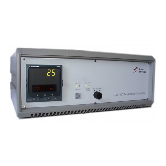
Design of the instrument Front view 1 EUROTHERM controller 2 Heater button and LEDs to show ON/OFF status 3 Cooling water cycle LEDs to show ON/OFF status 4 Speed control for sample spinner B39IB14-C... -
Page 12: Rear View
Rear view 1 Mains connector with mains fuses 2 Connection cables to the HTK 1200 heater 3 Connection cable for temperature measurement 4 Connector for water flow controller 5 Connector for sample spinner 6 RS 232 C serial port B39IB14-C... -
Page 13: Installation Of The Tcu 1000
Installation of the TCU 1000 The TCU 1000 control unit can be either installed in a 19" rack or used as table housing. If the instrument will be installed into a rack, the supplied guide bars have to be used. -
Page 14: Installing Into A 19" Rack
6.1.2 Installing into a 19" rack For using the TCU 1000 into a 19" rack, the supplied guide bars have to be attached. To mount the guide bars, proceed as follows: 1. Loosen the screws (2) on both sides of the instrument´s bottom. -
Page 15: Mains Connection
Mains connection The mains connector (1) is located at the rear of the instrument. The TCU 1000 is operated on 230 VAC ±10%. Maximum power consumption is 1750 VA. Hint: • The protective conductor of the instrument has to be connected to ground! Warning: •... -
Page 16: Connecting The Flow Controller
The flow controller has to be connected to the "WATERFLOW CONTROL" connector (1) at the rear panel. A suitable flow controller (Cat. No. 70067) is available from Anton Paar Gmbh PIN-assignment of connector WATER FLOW CONTROL: Connected to flow controller magnetic switch Not connected... -
Page 17: Interfacing A Computer
Interfacing a computer The RS 232 C serial port at the rear panel allows to interface a computer for controlling the EUROTHERM controller . According to EN60950 standards, the RS 232 C serial interface represents a SELV circuit which therefore is allowed to be connected exclusively to SELV or SELV-E circuits. -
Page 18: Operation Of The Tcu 1000
Also the actual status of the TCU 1000 is shown on the display. To turn on the TCU 1000, press the mains switch at the rear panel of the instrument. The green LED for "WATERFLOW" and the green LED for "HEATER"... -
Page 19: Keypad And Key Functions Of The Eurotherm Controller
There are different levels of access for the operating parameters available in the controller. All parameters for operating the TCU 1000 with the HTK 1200 are predefined by Anton Paar GmbH. B39IB14-C... -
Page 20: User Interface Of The Controller
7.1.2 User interface of the controller Temperature at the sample holder Status field Parameter field 7.1.2.1 Temperature at the sample holder The current temperature at the sample holder is shown. If the temperature display reads "S.br." (sensor break), either the connection cable for temperature measurement is not connected or the temperature sensor at the sample holder is defective. -
Page 21: Status Field
This value is just for your information and cannot be changed. If you use the EUROTHERM software “iTools” you have to change the protocol from factory setting “EI-Bisynch” to “Modbus”.For further information see the Anton Paar instruction you get with “iTools” Hint: EI-Bisynch is a proprietary EUROTHERM protocol based on ANSI X3.28-25 A4 standard for message framing. -
Page 22: Function Of The Heater Button
PAGE SCROLL Using the "DOWN" key you can select the "Config" menu. After entering the password, modifications are possible for authorized personnel only! To get back to the parameter-menue press the PAGE key and SCROLL key together. Function of the heater button The Heater button (1) allows to stop manual heating and selects standby mode (Heating power OP = 0%;... -
Page 23: Sample Spinner
Sample spinner If a sample spinner is connected, use the speed control knob (1) to select the desired speed. B39IB14-C... -
Page 24: Performing A Measurement
Performing a measurement The TCU 1000 is designed for controlling the temperature of the HTK 1200 High Temperature Camera. 1. Install the TCU 100, as described in chapter 6. 2. For the installation of the High Temperature Camera, please refer to the HTK 1200 Instruction Handbook. -
Page 25: Troubleshooting
Troubleshooting Heating If there is a problem, the TCU 1000 selects the manual mode. For a short time the message LBR appears in the status field of the EUROTHERM controller. This is then replaced by man. (Heating power = 0 %) Possible sources of error: •... -
Page 26: Cooling Water Cycle
Cooling water cycle If there is a problem concerning the cooling water cycle or if the flow controller is not connected, the TCU 1000 selects the standby mode. The flow controller (yellow LED) flashes and the message SBY appears in the status field of the EUROTHERM controller (heating power OP = 0%). -
Page 27: Maintenance
10. Maintenance The TCU 1000 temperature control unit is maintenance-free. B39IB14-C... -
Page 28: Appendix A - Specifications
23 kg Class of overvoltage: II according to EN 61010 Class of contamination: 2 according to EN 61010 Electromagnetic compatibility (89/336/EWG) Applied standards (when using the TCU 1000): Electromagnetic compatibility, RF-Emissions: EN50081-1:1993 Electromagnetic compatibility, RF-Susceptibility: EN50082-1:1993 Directive on Low-Voltages (73/23/EWG) Applied standards (when using the .. -
Page 29: Appendix B - Warranty
12. Appendix B - Warranty The warranty regulations for the TCU 1000 are in accordance with the „General Terms of Delivery“ of the Austrian Electrical and Electronic Industry. B39IB14-C... -
Page 30: Index
Index Access levels 21 Accessory parts 6 Anton Paar GmbH 3 Auto/Manual Key 19 Comm. Protocol 21 Connect Flow controller 16 HTK 1200 camera 15 Sample spinner 16 Down Key 19 E-mail 3 EI-Bisynch 21 EUROTHERM Access levels 21 Key functions 19... - Page 31 Important 9 Installation of the Domed Hot Stage 24 Internet 3 Items 10 LBR 21 Loop Key 19 Mains connector 15 Missing parts 10 OP 20 Packing material 10 Page Key 19 Performing a measurement 24 Pin-assignment RS 232 C 17 SAMPLE SPINNER 16 WATER FLOW CONTROL 16 power switch 8...
- Page 32 Scroll Key 19 Serial port 17 Shipment 10 SP 20 Specifications 28 SPR 20 SRL 20 Supplied items 10 Symbols 9 Table housing 13 Telephone 3 Transport 10 Troubleshooting 25 Up Key 19 Warning 9 Warranty 29 WSP 20 B39IB14-C...
Need help?
Do you have a question about the TCU 1000 and is the answer not in the manual?
Questions and answers