Anton Paar DMA 4100 M Instruction Manual
Hide thumbs
Also See for DMA 4100 M:
- Instruction manual (78 pages) ,
- Instruction manual and safety information (30 pages)
Table of Contents
Advertisement
Advertisement
Table of Contents

Related Manuals for Anton Paar DMA 4100 M


Summary of Contents for Anton Paar DMA 4100 M
- Page 1 Instruction Manual DMA 4100 M DMA 4500 M DMA 5000 M Firmware Version: V2.21...
- Page 3 Instruction Manual DMA 4100 M DMA 4500 M DMA 5000 M Firmware Version: V2.21...
- Page 4 Anton Paar GmbH assumes no liability for technical or printing errors or omissions in this document. Nor is any liability assumed for damages resulting from information contained in the document. Anton Paar GmbH reserves the right to content changes. This also extends to changes to delivery volumes or any features of delivered parts.
-
Page 5: Table Of Contents
Contents 1 About the Instruction Manual ......................9 2 Safety Instructions......................... 10 3 The Measuring Principle ....................... 13 4 The Instrument - An Overview ...................... 14 5 Checking the Supplied Parts ......................16 6 Functional Components........................ 19 View of the Front and Right Side ................... 19 View of the Left Side...................... - Page 6 10.1.3 Input Units ......................42 10.1.4 Air Pump Settings....................42 10.1.5 Saving a Camera Picture (DMA 4500/5000 M Only)..........42 10.1.6 Network ........................42 10.1.7 Instrument Name and Location ................43 10.2 Defining the Printout Settings ....................43 10.2.1 Creating, Editing and Deleting Printer Report Layouts........... 43 10.2.2 Defining Header and Background of the Printer Report.........
- Page 7 12.4 Selecting the Method ......................70 13 Measuring ............................71 13.1 General Sample Settings....................... 71 13.2 Using the "No Sample List" Mode..................72 13.3 Using the "Sample List" Mode ....................72 13.4 Filling Samples ........................75 13.5 Performing Measurements ....................78 13.6 Filling and Measurement Errors.....................
- Page 8 Appendix A: Technical Data ......................114 A.1 Measuring Performance ..................114 A.2 Wetted Parts.......................115 A.3 General Technical Data ..................116 Appendix B: Measuring Special Samples ................... 117 B.1 Degassing Samples ...................117 B.2 Special Filling Techniques ..................118 Appendix C: Measuring under Special Conditions ..............119 C.1 Measuring at High Humidity/Low Temperature Conditions ........119 C.2 Measuring at Low/High Temperatures...............
-
Page 9: About The Instruction Manual
If you receive any additions or revisions to this instruction manual from Anton Paar GmbH, these must be treated as part of the instruction manual. -
Page 10: Safety Instructions
• Only use DMA 4100/4500/5000 M for the purpose described in this instruction manual. Anton Paar GmbH is not liable for damages caused by incorrect use of DMA 4100/4500/5000 M. • The results delivered by DMA 4100/4500/5000 M not only depend on the correct functioning of the instrument, but also on various other factors. - Page 11 • Do not use any accessories or wearing parts other than those supplied or approved by Anton Paar GmbH. • Make sure all operators are trained to use the instrument safely and correctly before starting any applicable operations.
- Page 12 Service and repairs • Service and repair procedures may only be carried out by authorized personnel or by Anton Paar GmbH. • Prior to sending DMA 4100/4500/5000 M to your representative or Anton Paar GmbH for repair or service, make sure that all liquids and solvents are completely drained out of the instrument.
-
Page 13: The Measuring Principle
3 The Measuring Principle 3 The Measuring Principle Definition of density and specific gravity The density ρ of a sample is defined as mass divided by volume: ρ ---- - The specific gravity SG is calculated by dividing the density of a sample by the density of pure water at 20 °C: ρ... -
Page 14: The Instrument - An Overview
Error detection A major source of measuring errors when using density meters are gas bubbles in the measuring cell. This issue was addressed by Anton Paar with two new features: C76IB003EN-E... - Page 15 4 The Instrument - An Overview • FillingCheck : The instrument automatically detects inhomogeneities and gas bubbles in the whole measuring cell by an advanced analysis of its oscillation pattern and generates a warning message in real time for any single measurement.
-
Page 16: Checking The Supplied Parts
2. Check the delivery for completion by comparing the supplied parts to those noted in Table 5.1. 3. If a part is missing, contact your Anton Paar representative. 4. If a part is damaged, contact the transport company and your Anton Paar representative. Table 5.1: Standard parts Symbol Pcs. - Page 17 5 Checking the Supplied Parts Table 5.1: Standard parts Symbol Pcs. Article Description Mat. No. Density standard "ultra-pure water" 5x10 mL with 96044 certificate Accessory kit 70248 Hose 3 x 5 mm silicone (transparent) 50814 Syringe 2 mL Luer 51974 Injection adapter Luer 12225 Male Luer plug PTFE...
- Page 18 5 Checking the Supplied Parts Table 5.2: Optional parts Article Description Mat. No. Data handling Keyboard German USB 80809 Keyboard USA USB 80807 POS printer RS-232C incl. cable 9600N81 44737 Printer Epson TM-U220D for DMA M 93362 RS-232 connection cable 9 pin 3 m 70429 Gender changer DB9M/DB9M 302592...
-
Page 19: Functional Components
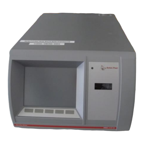
6 Functional Components 6 Functional Components View of the Front and Right Side Fig. 6 - 1 View of the front and right side of DMA 4100 M ... Softkeys ... Color TFT touch screen ... Power on LED ... Inspection window for the measuring cell (DMA 4100 M only) ... -
Page 20: Rear View
6 Functional Components Rear View Fig. 6 - 3 Rear view ... RS-232 interface (COM) ... S-BUS interfaces ... USB interface ... VGA interface ... Ethernet interface ... CAN interface ... "DRY AIR IN AIR PUMP" connector ... "DRY AIR IN BLOCK" connector ... -
Page 21: Operating Elements Of The Main Screen
6 Functional Components Operating Elements of the Main Screen Header Content area Quick access area Output field Progress Buttons area Fig. 6 - 4 Main screen example Header In the left part of the header, you find the name of the currently active method and the sample number. - Page 22 6 Functional Components Quick access buttons To open the diagnosis list. The general instrument status as well as all measuring errors that have occurred during the measurements of the currently active sample list are described in this list. The button changes its appearance depending on the current error status: With green check: The general instrument status and the error status of all measured...
-
Page 23: Operating Elements Of The Menu Screen
6 Functional Components Monitor mode If you have not started a measurement yet, or if you have terminated a measurement by tapping <Stop>, the instrument is in the monitor mode and shows a continuous reading of the current measuring values. Measuring mode If you have started a measurement, the continuous measuring values are shown until the measurement is finished. -
Page 24: Installing The Instrument
7 Installing the Instrument 7 Installing the Instrument To install the instrument, put it on a bench, mount injection adapters and hoses and connect the instrument to the mains. Define general instrument settings and perform an air/water check to check the validity of the factory adjustment. For the installation of an Xsample filling module, see the respective instruction manual. -
Page 25: Checking For Leak Tightness
7 Installing the Instrument Keep the black transport plastic plugs for later. They can be used as an injection adapter tool to widen the tips of the adapters in case of leaks. Fig. 7 - 1 Mounting the Luer injection adapters 3. -
Page 26: Mounting The Hoses
7 Installing the Instrument If the connections are leaking, the plunger will not move. In this case, repeat the mounting of the adapters. Mounting the Hoses To connect the waste vessel WARNING Liquids leaking from the instrument may cause injuries and risk of fire. •... -
Page 27: Switching The Instrument On/Off
7 Installing the Instrument Switching the Instrument On/Off WARNING High voltage at parts of the instrument can cause serious injuries or death. • Only connect the instruments to the mains via protective earthing. • Never connect the instrument to the mains via protective separation or protective insulation. -
Page 28: Operating The Instrument
8 Operating the Instrument 2. To perform an air check, tap <Menu> and select "Checks/Adjustments > Checks" (see Chapter 11.2.2). 3. To perform a water check, tap <Menu> and select "Checks/Adjustments > Checks" (see Chapter 11.2.2). 4. Follow the instructions on the screen. 5. -
Page 29: Using The Touch Screen
8 Operating the Instrument To navigate within lists • To move the cursor one line up or down within the list, press the <↑> or <↓> key on your external keyboard. • To move the cursor one page up or down, press the <PgUp> or <PgDn> key on your external keyboard. - Page 30 8 Operating the Instrument Fig. 8 - 1 Example: "Change Quantity" list with "Density" highlighted To use drop-down boxes 1. Tap on the drop-down box and then highlight an item in the drop-down list. 2. Tap <OK> to select the entry and close the list. Check box Drop-down box Fig.
- Page 31 8 Operating the Instrument Fig. 8 - 3 Example: Radio buttons in the "Camera" dialog (menu "Setup > Measurement System Settings > Camera") To enter characters into an input box or list field 1. There are two ways to open the on-screen keyboard: •...
- Page 32 8 Operating the Instrument 2. Enter characters/numbers/special characters by tapping the buttons on the screen and then tap <OK>. Fig. 8 - 5 On-screen keyboard The functions of the special buttons are: Deletes the character on the left side of the cursor position. Moves the cursor position to the left/to the right.
-
Page 33: Calibrating The Touch Screen
8 Operating the Instrument To exit wizards with/without saving A wizard is a combination of two or more dialog windows. You have three options to exit a wizard: • To get one level up and save the settings, complete all steps of the wizard and then tap <OK>. -
Page 34: Activating/Deactivating The Feedback Beeps
8 Operating the Instrument To set the time 1. Tap <Menu> and select "Setup > Control Panel > Screen Saver" to open the settings for the screen saver. 2. Use the check box to activate/deactivate the option: • Automatically switch off display after ... minutes. 3. -
Page 35: Using Favorites
8 Operating the Instrument 2. Select your "User name", enter your "Password" and tap <OK>. NOTICE If the instrument is used in the increased security mode, your user account will be deactivated after three failed logon attempts. To log off 1. - Page 36 8 Operating the Instrument To change the sequence of the favorites list 1. Tap <Menu> and select "Setup > Favorites Management". 2. Highlight the list item and use the up/down arrows in the right column to change the position of the list item in the favorites list. 3.
-
Page 37: Installing Optional Input/Output Devices
In this chapter, you find information about the installation of optional input/output devices. For detailed information on the devices, see the respective manual. If you are using accessories that are not supplied by Anton Paar, we do not guarantee their functionality and safety. -
Page 38: Usb Flash Drive
(COM) of the instrument using the cable that is supplied together with the printer. 2. If you use an RS-232 printer which is not supplied by Anton Paar, set the communication settings on the printer properly (see Appendix A.3). To connect an office printer (not supplied by Anton Paar) via USB interface •... -
Page 39: Registering, Editing, Deleting A Printer
9 Installing Optional Input/Output Devices 5. Enter the primary and secondary DNS and tap <OK>. 6. Connect the printer to your local network. For details, see the printer instruction manual. 9.3.2 Registering, Editing, Deleting a Printer You can register up to 5 printers. To register a new printer or edit a printer 1. -
Page 40: External Terminal Or Data Projector
Printing and Exporting Results and Other Data: Chapter 15.6 External Terminal or Data Projector The external terminal or data projector (not supplied by Anton Paar) has to be capable of delivering a 640 x 480 px resolution in true color (VGA) at minimum 60 Hz. -
Page 41: Defining General Settings
10 Defining General Settings 10 Defining General Settings 10.1 Instrument Settings These settings are not method-dependent and thus will not change after a change of the current method. 10.1.1 Date and Time 1. Tap <Menu> and select "Setup > Control Panel > Date and Time". 2. -
Page 42: Input Units
10 Defining General Settings 10.1.3 Input Units In this menu, you can define the unit for every temperature value which you enter during operation. 1. Tap <Menu> and select "Setup > Control Panel > Input Units". 2. Select the input unit for temperatures and tap <OK>. 10.1.4 Air Pump Settings You can set the timeout after which the air pump is stopped and the condition on which the air pump is stopped. -
Page 43: Instrument Name And Location
10 Defining General Settings 2. If your network server has DHCP functionality, activate "Obtain an IP address automatically (DHCP)", then tap <Next> and <OK>. 3. If your network server has no DHCP functionality, deactivate "Obtain an IP address automatically (DHCP)" and enter the correct "IP Address", "Subnet Mask", "Default Gateway", and tap <Next>. -
Page 44: Defining Header And Background Of The Printer Report
10 Defining General Settings 4. Tap <Next> and perform the following settings: • Define the paper format (portrait or landscape). • Activate/deactivate the check box "Print Camera Image". 5. Tap <Save>. To delete a report 1. Tap <Menu> and select "Setup > Printout Settings > Report Management"... -
Page 45: Activating/Deactivating An Automatic Printout
10 Defining General Settings To enter name and address for the header 1. Tap <Menu> and select "Setup > Printout Settings > Name and Address". 2. Enter the name and address and tap <OK>. 10.2.3 Activating/Deactivating an Automatic Printout 1. Tap <Menu> and select "Setup > Printout Settings > Automatic Printout". 2. - Page 46 10 Defining General Settings • Define mandatory data fields. The measurement can only be started after filling in the mandatory data fields. If mandatory data fields are not completed in the sample list, these fields will be prompted again for completion after the start of the measurement.
-
Page 47: Installing User Accounts And Passwords
10 Defining General Settings To set mandatory data fields You can set the sample name and user-defined data fields as mandatory. 1. Tap <Menu> and select "Setup > Measuring System Settings > Sample List > Mandatory Data Fields". 2. Use the check box(es) to define whether it is mandatory to enter a sample name or content for user-defined data fields for each measurement. -
Page 48: Creating, Editing And Deleting User Accounts
The password must have at least one character. Allowed are characters from the ASCII table which are letters, numbers and most special characters. The password is case sensitive, for example "Anton Paar" or "anton paar" does make a difference in the logon. - Page 49 10 Defining General Settings To create or edit a user account 1. Tap <Menu> and select "Setup > User Management". 2. Tap <New> to create a new user account or highlight a user name on the user list and tap <Edit> to edit a user account. The "Edit User"...
-
Page 50: Checking, Adjusting And Calibrating The Instrument
You can edit the name, method (custom check only), time interval and the tolerance of density checks. Tolerance The factory presets for the check tolerance for both air and water checks are: DMA M Model Tolerance DMA 4100 M 0.0002 g/cm DMA 4500 M 0.0001 g/cm DMA 5000 M 0.00005 g/cm To edit the settings of the Air Check and Water Check 1. - Page 51 11 Checking, Adjusting and Calibrating the Instrument 2. Highlight the "Air Check" or "Water Check" and tap <Edit> to open the two- step "Check Edit" wizard. 3. Perform the following settings: • Enter a name for the check. • Use the check box "Must be started every" to define if the check is obligatory and enter a time interval in days.
-
Page 52: Performing Density Checks
11 Checking, Adjusting and Calibrating the Instrument 11.2.2 Performing Density Checks With density checks, carried out in regular intervals, you can ensure a high and stable accuracy of your density and concentration measurements. During a density check, you fill a medium of known density (air, water or any customer-specific standard liquid) into the measuring cell and compare the measured density with the reference value. -
Page 53: Viewing, Printing Or Exporting Current Check Data
11 Checking, Adjusting and Calibrating the Instrument For a water check use freshly degassed ultra-pure (bi-distilled or deionized) water. For an air check clean and dry the measuring cell properly. Use the camera image to check whether the measuring cell is clean or water was filled bubble free. -
Page 54: Adjustments
11 Checking, Adjusting and Calibrating the Instrument 11.3 Adjustments 11.3.1 Performing an Air/Water Adjustment An air/water adjustment has to be performed if the water check had a "not passed" result and using freshly degassed ultra-pure water and cleaning the measuring cell did not help. The adjustment media are dry air and freshly degassed ultra-pure (bi-distilled or deionized) water. -
Page 55: Performing A Temperature Range Adjustment
11 Checking, Adjusting and Calibrating the Instrument The water adjustment routine is carried out. When the adjustment is finished, the following information is displayed: • Old Value: Calculated density of water of the previous adjustment. • New Value: Calculated density of water with the new adjustment constants. •... -
Page 56: Performing A High Density/High Viscosity Adjustment (Dma 5000 M Only)
11 Checking, Adjusting and Calibrating the Instrument 11.3.3 Performing a High Density/High Viscosity Adjustment (DMA 5000 M only) With a DMA 5000 M, you can perform an adjustment at high density and/or at high viscosity to reach an exceptionally high accuracy for the measurement of high density values and/or samples with a high viscosity. -
Page 57: Performing Special Adjustments
11 Checking, Adjusting and Calibrating the Instrument 2. Use a calibrated external pressure sensor to get an exact pressure value. Do not use the atmospheric pressure that you can get from a local weather station, because this usually is not the absolute atmospheric pressure, but a calculated atmospheric pressure at sea level. - Page 58 11 Checking, Adjusting and Calibrating the Instrument Hints for measurements using special adjustments If the instrument is operated using a special adjustment, the set measuring temperature must be the same as the temperature at which the special adjustment was performed. Otherwise no results will be obtained. No viscosity correction is available if the instrument is operated using a special adjustment.
-
Page 59: Special Adjustment For The Canadian Excise Alcohol Table
11 Checking, Adjusting and Calibrating the Instrument 11.3.5.2 Special Adjustment for the Canadian Excise Alcohol Table To use the output quantity "Canadian Excise Alcohol Table" (see Appendix F), it is necessary to perform a special adjustment with apparent density values of air and water and link that adjustment to the Canadian Excise Alcohol Table. -
Page 60: Calibrating
11 Checking, Adjusting and Calibrating the Instrument 2. Activate the check box "Density Module" and tap <OK>. 11.4 Calibrating The goal of a calibration is to validate the accuracy of the density measurement. To calibrate the instrument, measure a certified standard liquid and compare the result to the reference value indicated in the calibration certificate of the standard. -
Page 61: Defining And Using Methods
12 Defining and Using Methods 9. Document the calibration procedure in a calibration protocol which contains the operator’s name, date, place, description of the calibration procedure, results and the calibration certificate of the liquid density standard. Related topics Performing Density Checks: Chapter 11.2.2 Performing an Air/Water Adjustment: Chapter 11.3.1 Cleaning and Drying the Measuring Cell: Chapter 14.1 Defining and Using Methods: Chapter 12... - Page 62 12 Defining and Using Methods Density (not visc.-corr.) • Density (not visc.-corr.), Specific Gravity (not visc.-corr.), Density Temperature, Density Condition, U-View • General purpose method, for comparison with old instruments without viscosity correction °Brix • Concentration Sugar, Density, Density Temperature, Density Condition, U-View •...
- Page 63 12 Defining and Using Methods Ethanol (°Proof 60 °F AOAC) • Ethanol Proof 60 °F, Density, Density Temperature, Density Condition, U-View • For measurements of alcohol concentration in distillates Crude Oil (API) • API Density 15 °C, Density, API Specific Gravity 15 °C, Density Temperature, °API Gravity 15 °C, Density Condition, U-View •...
-
Page 64: Changing Methods
12 Defining and Using Methods Sulfuric Acid (% w/w) • Sulfuric Acid (H ) (% w/w), Density, Density Temperature, Density Condition, U-View • For measurements of sulfuric acid up to 94 % w/w 12.2 Changing Methods You need administrator rights to create, edit or delete methods. Up to 50 methods can be created. -
Page 65: Defining The Displayed Output Fields
12 Defining and Using Methods 4. Define the "Timeout". 5. Use the drop-down box "FillingCheck " to select one of the options: • always active • active during a measurement • not active 6. Tap <OK>. 12.2.2 Defining the Displayed Output Fields For each method, you can select the number and content of output fields on the display. -
Page 66: Defining Limits
12 Defining and Using Methods To define the list of output quantities 1. Tap <Menu> and select "Methods > Method Settings > "Method Name" > Result Output". 2. Tap on the list item that you want to change or on the empty field at the bottom of the list if you want to add an item. -
Page 67: Defining Multiple Measurements
12 Defining and Using Methods 12.2.5 Defining Multiple Measurements Using multiple measurements enables you to perform several measurements automatically. A single entry in the sample list starts a series of up to 10 measurements of a sample and calculates the average value of these measurements. -
Page 68: Defining Quick Setting Parameters
User-defined data fields (see Chapter 10.3) and user functions of the "Constant" type (see Chapter 16.2) will be automatically added to your quick settings. If you have connected one or more Anton Paar measuring modules to your master instrument, the range of parameters that can be added to your quick settings will be extended. -
Page 69: Creating, Deleting, Hiding And Arranging Methods
12 Defining and Using Methods To change the sequence of the quick setting parameters 1. Tap <Menu> and select "Methods > Method Settings > "Method name" > Quick Settings Management". 2. Highlight a parameter and use the up or down arrow in the "Order" column to change the position of the parameter in the list. -
Page 70: Selecting The Method
12 Defining and Using Methods 2. Highlight a method name and tap <Rename>. 3. Enter the new method name (up to 50 characters long). 4. Tap <OK>. To delete a method 1. Tap <Menu> and select "Methods > Method Management" to open the method list. -
Page 71: Measuring
13 Measuring Related topics Making a Backup of the Instrument Settings: Chapter 17.1 13 Measuring In this chapter, the filling of samples and the measuring procedure including the detection of bubbles are described. 13.1 General Sample Settings Sample name If you have defined automatic sample name parts (see Chapter 10.3), they will be added to each sample name after measurement has been finished. -
Page 72: Using The "No Sample List" Mode
13 Measuring The minimum step size in temperature scans depends on the defined type of equilibrium (Measurement finished by) of the density module: Measurement finished by Minimum step size Model Predetermined 1 °C DMA 4100/4500/5000 M Equilibrium 0.02 °C DMA 4100/4500 M Equilibrium fast 0.02 °C DMA 5000 M... - Page 73 13 Measuring Number of entries The sample list can contain up to 200 entries. The 201st entry overwrites the oldest entry. Entries older than 24 hours are automatically removed. The sample list will be automatically cleared if you switch off the instrument. NOTICE In the "Sample List"...
- Page 74 13 Measuring 3. Choose one of the 10 available entries in the drop-down list "Sample list templates". 4. Tap <Rename> and enter a name for your sample list. 5. Tap <OK>. To load a sample list 1. Tap <Sample List> and then <List Management>. 2.
-
Page 75: Filling Samples
13 Measuring 13.4 Filling Samples To achieve highly accurate measuring results, fill the samples into the measuring cell homogeneously and without bubbles. WARNING Filling samples and cleaning liquids which the wetted parts are not resistant to will corrode the wetted parts. Sample leaking from corroded parts may cause serious injuries. - Page 76 4. Tap <X> to exit the measuring cell view. Fig. 13 - 1 Camera window Bubble detection using the inspection window (DMA 4100 M) You can check the quality of the filling visually by looking through the inspection window at the front of the instrument.
- Page 77 13 Measuring Fig. 13 - 2 Filling with a syringe 1. Connect the syringe to the sample inlet adapter. 2. Push the plunger of the syringe slowly and continuously until a drop emerges from the sample outlet adapter. 3. Leave the syringe in the filling position during the measurement. To fill with a funnel 1.
-
Page 78: Performing Measurements
13 Measuring 2. Connect the adapter Luer cone with the sample container using a silicone hose (3 x 5 mm). 3. Mount an adapter Luer cone to the sample outlet adapter. 4. Connect a silicone hose (3 x 5 mm) to the adapter Luer cone and lead the silicone hose via the peristaltic pump to a waste vessel. - Page 79 13 Measuring The progress bar shows the progress of the measurement with a growing red bar and the message "Measuring". During measurements the last 1, 2 or 3 digits might be gray colored. This means that the set temperature has not been reached yet. In that case, only the black colored digits are valid.
-
Page 80: Filling And Measurement Errors
Note: For complete transparency and traceability of your sample filling and measurement process, check the filling visually by means of the built-in camera (U-View , DMA 4500/5000 M) or the inspection window (DMA 4100 M) in addition to the fully automatic FillingCheck C76IB003EN-E... -
Page 81: Cleaning And Storing The Instrument
14 Cleaning and Storing the Instrument FillingCheck provides excellent support to the operator for samples of low and medium viscosity ranges. High viscous samples above 3000 mPa·s, which firmly enclose contained air bubbles, might not be analyzed correctly and generate a filling warning even if filled without bubbles. - Page 82 14 Cleaning and Storing the Instrument Cleaning liquids For cleaning and drying, employ two cleaning liquids: • Cleaning liquid 1 dissolves and removes sample residues in the measuring cell. It has to be a good solvent for all sample components. •...
-
Page 83: Storing The Instrument
14 Cleaning and Storing the Instrument 6. Tap the button in the quick access area to start the air pump. 7. Wait until the measuring cell is dry (stable density reading). The time needed depends on the vapor pressure of your cleaning liquid 2 and the temperature of the measuring cell (Ethanol at 20 °C: approx. -
Page 84: Handling The Measurement Data
15 Handling the Measurement Data NOTICE Never use: • highly nonpolar solvents (e.g. toluene, hexane, solvent naphtha) • strong acids or bases (e.g. nitric acid, sulfuric acid, hydrochloric acid, caustic soda) • strong mechanical action (steel brush). Related topics Measuring in Harsh Environments: Appendix C.4 15 Handling the Measurement Data 15.1 Defining the Data Memory Settings Your instrument can store 1000 result data files with or without camera pictures. -
Page 85: Viewing Results
15 Handling the Measurement Data The row is highlighted. 3. Tap on the highlighted list item to get to the "Change Quantity" dialog. 4. Use the drop-down boxes to define the "Group", "Quantity", "Unit" and the number of "Digits". 5. Tap <OK>. To change the sequence of the data 1. -
Page 86: Filtering Results
15 Handling the Measurement Data 3. Use the <> or <> button to see the previous or next result. 15.4 Filtering Results With the filter tool, you can reduce the number of measuring results in the multiple and in the single sample view. Filter settings can be defined separately: •... -
Page 87: Viewing Statistics
15 Handling the Measurement Data 4. Tap <OK> to get back to the multiple sample view. The multiple sample view and the single sample view now only show those results that meet your filter criteria. Examples: • If you only want to see the samples that were measured with the method "°Brix", choose the following settings: •... -
Page 88: Printing And Exporting Results And Other Data
15 Handling the Measurement Data 4. For each output quantity the following statistics are displayed: No. of Values Number of measurements Minimum Lowest value Maximum Highest value Average Arithmetic mean value StdDev Standard deviation 15.6 Printing and Exporting Results and Other Data Your instrument supports three kinds of printouts: •... -
Page 89: Deleting Results
15 Handling the Measurement Data Related topics Filtering Results: Chapter 15.4 Activating/Deactivating an Automatic Printout: Chapter 10.2.3 Creating, Editing and Deleting Printer Report Layouts: Chapter 10.2.1 Defining Header and Background of the Printer Report: Chapter 10.2.2 Registering, Editing, Deleting a Printer: Chapter 9.3.2 Defining the Result Output: Chapter 12.2.3 15.7 Deleting Results We recommend deleting your result data regularly after a successful data export... -
Page 90: Using Special Functions
16 Using Special Functions 16 Using Special Functions 16.1 System Security You can enable different system security settings to ensure data security and to protect your measuring system from unauthorized access. 16.1.1 Security Level Depending on your needs you can set different security levels: low or 21 CFR Part 11 compliant. -
Page 91: Auto Logoff And Password Expiry
16 Using Special Functions 3. If you want to compare your current settings and the settings that will be affected by changing the security level, tap <Details>. The settings affected by changing the security level will be highlighted with red letters. 4. -
Page 92: Audit Trail
16 Using Special Functions Table 16.2: Increased security settings No endless data storage allowed Endless data storage allowed Only user-defined sample list mode All sample list types allowed allowed Lock user account after three failed User account is not locked after failed logon attempts logon attempts Auto Logon is not allowed... - Page 93 16 Using Special Functions • Changes of user accounts (creating, editing, activating, deactivating, deleting, changing a password) • Saving and restoring of parameter settings and configurations • Deletion of measured data (number of deleted measuring data and corresponding unique sample ID) •...
-
Page 94: Electronic Signature
16 Using Special Functions All audit trail entries that have already been exported are deleted. For data safety reasons, it is not possible to delete audit trail entries that have not been exported before. Verifying the integrity of audit trail exports Audit trail data exports are protected by a MD5 checksum file that is exported together with the data file to guarantee full traceability. - Page 95 16 Using Special Functions Example: If a sample is signed as positive by the approver prior to a submitter or reviewer, the signing states of submitter and reviewer are also set as positive consequently. Signing states With the electronic signature activated, three boxes appear in the first column of the data table in the multiple sample view next to the sample error state icon.
-
Page 96: User Functions - Constants, Formulas, Polynomials And Tables
16 Using Special Functions 1. Tap <Menu> and select "Data Memory > Measured Data". 2. Highlight the sample that shall be signed. 3. Change to the single sample view by tapping <Single Sample>. 4. Tap the corresponding signing role button. 5. - Page 97 16 Using Special Functions To program or edit a constant The "Constant" user function is used to integrate a user-defined value to the result output. The constant can describe every quantity needed and does not need to be directly measured with your measuring system. The constant can be also be integrated in other user functions or changed if needed.
- Page 98 16 Using Special Functions To program or edit a formula 1. Tap <Menu> and select "Setup > Expert Settings > User Function Management" to open the user functions list. 2. Tap <New> to program a new formula or highlight a list item and tap <Edit> to edit a formula.
- Page 99 16 Using Special Functions • Activate/deactivate the check box "Protect function against changes by other users". • Enter a comment to describe this user function. This comment will not be printed, exported or displayed anywhere but is only an internal description of your user function. 5.
- Page 100 16 Using Special Functions 5. Tap <Next>. 6. Define the input quantity/quantities and tap <Next>. 7. Enter the polynomial coefficients. If you do not enter a value for a coefficient, the coefficient will be set to the value zero. 8. Tap <OK>. To program or edit a user table If you have a literature table or own experimental data about the density of a binary mixture at different concentrations, you can program this data into a user...
-
Page 101: Calculator
16 Using Special Functions To verify a user function You can directly check the output of your user function when you have finished the programming. Tap <Save and Try> at the last step of the "User Function" wizard (Step 4 of 4) to save the user function and to automatically switch to the calculator (see Chapter 16.3). -
Page 102: Group Calculator
16 Using Special Functions 2. Use the drop-down boxes to select the "Function" and the output "Unit" and tap <OK>. 3. Select "Manual Value Input (Calculator)" and tap <OK>. 4. Enter the "Value" for the input parameter(s) and tap <Next>. 5. -
Page 103: Service Utilities
17 Service Utilities 2. Use the drop-down box "Group", select the type and tap <Next>. 3. Enter the "Values" for the Input Quantities and tap <Next>. 4. Read out the calculated results. 5. To calculate further results with other values, tap <Previous> and repeat steps 3 and 4. -
Page 104: Restoring Instrument Settings
17 Service Utilities 4. Select the content of your backup file in the column "Value" and tap <OK>. 5. Tap <Yes> to create your backup file. The backup file is stored into the root directory of your USB flash drive. 17.2 Restoring Instrument Settings For version 1.70 and higher, you can restore any backup file made with version 1.60 or higher. - Page 105 17 Service Utilities NOTICE To update the firmware, you need administrator rights with activated auto logon function (see Chapter 10.4.2). Before starting the update of the user interface firmware, export or print relevant measurement data (see Chapter 15.6) and create a backup of the instrument settings (see Chapter 17.1).
-
Page 106: Viewing The System Information
17 Service Utilities 5. Follow the instructions on the screen. To install a language pack To receive a language pack, contact your Anton Paar representative. 1. Load the desired language pack into the root directory of your USB flash drive. -
Page 107: Viewing And Printing Live Raw Data
17 Service Utilities To change the log file configuration In special cases your Anton Paar representative will ask you to change the configuration of your log file in order to get more specific information about your instrument. 1. Tap <Menu> and select "Service > Update > Logging Configuration". - Page 108 17 Service Utilities RHOg5 Value Viscosity corrected density, valid if the viscosity is greater than 500 mPa·s. Status Value Status information indicating the temperature status of the cell. Calculations You can view a list of the calculations of the currently available output quantities. DCB - Air Pump Air Pump State Status of the air pump (0 or 1).
-
Page 109: Communication With External Pc And Lims
18 Communication with External PC and LIMS 18 Communication with External PC and LIMS 18.1 Connecting the Instrument to an External PC via Ethernet You can transfer the system information and a PDF file of the instruction manual from your instrument to any PC of your local network via Ethernet. 1. - Page 110 18 Communication with External PC and LIMS NOTICE If you have defined an RS-232 printer, make sure that you do not print anything (manually or automatically) while using the RS-232 interface for data transfer to a PC. Otherwise, there will be a conflict with the RS-232 printer and both the printout and data transfer will fail.
- Page 111 18 Communication with External PC and LIMS getdataunit Gets unit data of the output quantities of the last measured sample. For each output quantity the unit is returned. getdata Returns the result values of the last measurement only once. finished Returns the status of the measurement.
- Page 112 18 Communication with External PC and LIMS Command Response Description start wrong magazine position An Xsample sample filling module is active and the magazine position start method_number parameter is not valid (e.g. smaller than 1 or larger than the magazine start method_number size).
-
Page 113: Connecting The Instrument To A Lims
18.3 Connecting the Instrument to a LIMS The instrument can be connected to your Laboratory Information Management System (LIMS) using the Anton Paar software LIMS Bridge. LIMS Bridge can be used to send remote measurement commands from the LIMS to the instrument and to forward result files from the instrument to the LIMS. -
Page 114: Appendix A: Technical Data
Appendix A: Technical Data Appendix A: Technical Data Measuring Performance Table A.1: Technical data of measuring performance DMA 4100 M DMA 4500 M DMA 5000 M Measuring range 0 to 3 g/cm Repeatability density (s. d.) 0.00005 g/cm 0.00001 g/cm 0.000001 g/cm... -
Page 115: Wetted Parts
Appendix A: Technical Data Wetted Parts The following materials are in contact with samples and cleaning liquids: DMA M Material Part Borosilicate glass Measuring cell PTFE Filling adapter Standard accessories Material Part Polyethylene Waste vessel Polypropylene/Polyethylene Syringe 2 mL Luer PTFE Injection adapter Luer PTFE... -
Page 116: General Technical Data
Only connect devices to the interfaces that comply with PELV (protective extra-low voltage) according to EN 61140 or with SELV (safety extra-low voltage) according to EN 60950. NOTICE Connect only Anton Paar equipment or equipment with a maximum power consumption of 40 W to the CAN interface. C76IB003EN-E... -
Page 117: Appendix B: Measuring Special Samples
Appendix B: Measuring Special Samples Appendix B: Measuring Special Samples Degassing Samples There are different methods for the degassing of liquid samples. The preferable method for your application depends on the kind of sample and the amount of gas that is dissolved in the sample. Always take care that you treat all samples in the same way in order to get reproducible measuring results. -
Page 118: Special Filling Techniques
Liquids in aerosol cans For the quality control of aerosol cans, you can use the Anton Paar Aerosol Adapter (Mat. No. 74650) to fill the liquid safely and conveniently into your DMA M. For details, see the Aerosol Adapter instruction manual. -
Page 119: Appendix C: Measuring Under Special Conditions
Appendix C: Measuring under Special Conditions Appendix C: Measuring under Special Conditions Measuring at High Humidity/Low Temperature Conditions If the ambient air contains humidity and the measuring temperature is lower than the ambient temperature, condensation may occur in the measuring cell and measuring cell block. - Page 120 Appendix C: Measuring under Special Conditions For a measuring temperature of 20 °C, a drying cartridge must be used under the following conditions: Ambient temperature Relative air humidity (r. h.) 20 °C > 70 % 25 °C > 50 % 30 °C >...
-
Page 121: Measuring At Low/High Temperatures
Appendix C: Measuring under Special Conditions Measuring at Low/High Temperatures To measure at low temperatures To perform measurements at temperatures lower than 20 °C (36 °F) below ambient temperature, install the cooling kit (Mat. No. 80810) and connect the DMA M to an external thermostat. If your tap water is cool enough also connecting to a tap water supply will help. -
Page 122: Measuring At High Pressures
Appendix C: Measuring under Special Conditions Measuring at High Pressures The supplied silicone hose and injection adapters can only be used at atmospheric pressure. Before applying high pressures, exchange the supplied filling components with pressure-resistant components. WARNING Leaky components of the measuring system can cause sample to be splashed out when pressure is applied to the measuring system. - Page 123 Appendix C: Measuring under Special Conditions 2. Hold the new foil in one hand and use the thumb finger nail of the other hand to peel off the back liner from a small area. 3. Position the back liner free end of the foil on one edge of the display, hold the opposite end and bend the foil backwards.
-
Page 124: Appendix D: Adjusting The Camera Settings
Appendix D: Adjusting the Camera Settings Appendix D: Adjusting the Camera Settings Adjusting the Camera Position If the camera does not show the complete measuring cell, you can adjust the position of the camera. 1. Log on as "administrator". 2. Tap the button in the quick access area. -
Page 125: Appendix E: Trouble Shooting
Appendix E: Trouble Shooting Appendix E: Trouble Shooting Table E.1: Adjustment Problem Cause and Correction Readjustment is necessary Bad water quality for checks/adjustments: Use Chapter very often. freshly degassed ultra-pure (bi-distilled or 11.3.1 deionized) water. The measuring cell is not clean: Clean and dry the Chapter 14 measuring cell perfectly before an air check/ adjustment. - Page 126 Appendix E: Trouble Shooting Table E.2: Measurement Problem Cause and Correction The calibration failed. The Bad cleaning and drying: Improve your cleaning and Chapter 14.1 results deviate from drying procedure. reference values. The calibration liquid was stored too long: Use a fresh calibration liquid.
- Page 127 Appendix E: Trouble Shooting Table E.7: Printout problems Problem Cause and Correction No printout on office printer. Office printer problems: Check if the printer has enough paper, toner etc. See the respective printer instruction manual. The office printer type is not supported by your Chapter 9.3 instrument.
-
Page 128: Appendix F: List Of Output Quantities
The following quantities can be selected as output for the output fields. Group: System + Temperature Number of digits displayed with temperature values: DMA 5000 M: 3 DMA 4500 M: 2 DMA 4100 M: 2 DataField 1 Name of the user-defined data field (optional sample ID). DataField 2 Name of the user-defined data field (optional sample ID). - Page 129 Appendix F: List of Output Quantities Group: Density Number of digits displayed with density values: DMA 5000 M: 6 DMA 4500 M: 5 DMA 4100 M: 4 Apparent Density Brass Apparent density referring to scales which are adjusted with brass weights. Apparent Density Steel Apparent density referring to scales which are adjusted with steel weights.
- Page 130 (% w/w) according to ethanol concentration tables issued by different organizations/authors. Number of digits displayed with ethanol values: DMA 5000 M: 3 DMA 4500 M: 2 DMA 4100 M: 2 Canadian Excise Alcohol Table Special ethanol table converting the output of a special adjustment into an ethanol value.
- Page 131 Number of digits displayed with concentration values: DMA 5000 M: 3 DMA 4500 M: 2 DMA 4100 M: 2 Number of digits displayed with Mass Concentration Sugar: All 3 models: 1 Baumé Based on specific gravity at set temperature (t).
- Page 132 (% w/w) and mole per liter (mol/l) according to different tables. Number of digits displayed with % w/w values: DMA 5000 M: 3 DMA 4500 M: 2 DMA 4100 M: 2 Number of digits displayed with mol/L and N values: DMA 5000 M: 4 DMA 4500 M: 3...
- Page 133 Appendix F: List of Output Quantities Group: API Functions °API Gravity 20 °C API gravity converted to 20 °C. °API Gravity 29.5 °C API gravity converted to 29.5 °C. °API Gravity 60 °F API gravity converted to 60 °F. API Density 15 °C Conversion of density at measuring temperature to density at 15 °C.
-
Page 134: Appendix G: List Of Quick Settings Parameters
Appendix G: List of Quick Settings Parameters Appendix G: List of Quick Settings Parameters Parameter Type Parameter Select Description Sample Name Only in the "No Sample List" mode Type S (Standard) To perform a standard measurement C (Check) To perform one of the predefined checks. - Page 135 Appendix G: List of Quick Settings Parameters Parameter Type Parameter Select Description Density API Product A - Crude oil default Group B - Fuels D - Lubes None (use method default) Density API Input Density default Quantity Density (not visc. - corr.) Special Adjustment up to 5...
-
Page 136: Appendix H: Bar Codes For Assigning Methods
Appendix H: Bar Codes for Assigning Methods Appendix H: Bar Codes for Assigning Methods To generate a bar code for a method, you can use any bar code generator, e.g. http://barcode.tec-it.com. • Use the format "MethodX" with "X" standing for the position number of the method in the method list. -
Page 137: Appendix I: Density Tables
Appendix I: Density Tables Appendix I: Density Tables Density of Air At the temperature t in [°C] and the pressure p in [mbar] or [hPa] the density ρ of air in [g/cm ] is calculated using the following formula for an air humidity of 50 %: ρ=(((0.34844*p-0.5*(0.252*t-2.0582))/(273.15+t)/1000)) The numbers are valid for a CO content in air of 0.03 % by volume;... - Page 138 Appendix I: Density Tables Density of Water (0 °C to 100 °C) T °C .999840 .999846 .999853 .999859 .999865 .999871 .999877 .999883 .999888 .999893 .999899 .999903 .999908 .999913 .999917 .999921 .999925 .999929 .999933 .999937 .999940 .999943 .999946 .999949 .999952 .999954 .999956 .999959 .999961...
- Page 139 Appendix I: Density Tables T °C .993681 .993646 .993610 .993575 .993540 .993504 .993468 .993433 .993397 .993361 .993325 .993289 .993253 .993217 .993181 .993144 .993108 .993072 .993035 .992998 .992962 .992925 .992888 .992851 .992814 .992777 .992740 .992703 .992665 .992628 .992591 .992553 .992515 .992478 .992440 .992402 .992364...
- Page 140 Appendix I: Density Tables T °C .973632 .973571 .973510 .973449 .973388 .973327 .973266 .973205 .973144 .973083 .973021 .972960 .972899 .972837 .972776 .972714 .972653 .972591 .972529 .972468 .972406 .972344 .972282 .972220 .972158 .972096 .972034 .971972 .971910 .971847 .971785 .971723 .971660 .971598 .971535 .971473 .971410...
-
Page 141: Appendix J: Firmware Versions
Appendix J: Firmware Versions Appendix J: Firmware Versions Firmware Date of Document Comments version release number V1.00 18.06.2008 C76IB01A First released version. V1.10 14.08.2008 C76IB01B Users with administrator rights can update the Operating System and adjust the camera position. V1.52 27.02.2009 C76IB01C •... - Page 142 Appendix J: Firmware Versions Firmware Date of Document Comments version release number V2.00 10.09.2010 C76IB003EN-A • GUI performance improved • Data browser filter: only users and methods used are available • More detailed information about firmware module state during startup (new initialization screen instead of online screen) •...
- Page 143 Appendix J: Firmware Versions Firmware Date of Document Comments version release number V2.20 12.09.2011 C76IB003EN-C • New system security settings implemented: different security levels, electronic signature, auto logoff and password expiry • "Audit Trail" menu now in the "System Security" menu •...
-
Page 144: Appendix K: Declaration Of Conformity
Appendix K: Declaration of Conformity Appendix K: Declaration of Conformity C76IB003EN-E... -
Page 145: Appendix L: Menu Tree
Appendix L: Menu Tree Appendix L: Menu Tree The menu tree shows which parts of the menu are accessible for users with administrator, manager or operator rights using the following colors: Administrator Administrator, Manager Administrator, Manager, Operator Checks/Adjustments Checks Air/Water Adjustment Other Adjustments Density Module Air/Water Adjustment... - Page 146 Appendix L: Menu Tree Setup Measuring System Settings Sample List Sample List / Sample Settings User-defined Data Fields Sample List Warnings Mandatory Data Fields Camera Air Pump Control Panel Date and Time Regional Settings Input Units Printer Management Network Instrument Name and Location Screen Saver Feedback Beeps...
- Page 147 Appendix L: Menu Tree Service Live Raw Data DMA Density Calculations DCB - Air Pump DMA Density - Air Pressure DCB - Environment DCB - CAN Connector a. DMA 5000 M only b. Only if a "Constant" user function was created and/or if a module is connected c.
-
Page 148: Index
Index Index Symbols output quantities 132 API gravity 132 °Balling 131 API specific gravity 133 °Brix 131 apparent density 129 °Plato 131 apparent specific gravity 129 <Favorites> button 21 atmospheric pressure sensor 56 <Menu> button 21 audit 92 <Method> button 21 audit trail <Sample List>... - Page 149 Index Xsample filling equipment 82 cleaning liquids 82 equilibrium 64, 114 frequency 81 error status 22, 81 instrument housing 83 ethanol 62, 63, 82, 83, 114 touch screen 83 ethanol concentration 130 cleaning routine 81 ethanol tables 130 concentration measurement 13 external keyboard 37 accuracy 14, 114 external measuring module 106, 116...
- Page 150 Index hydrochloric acid 132 measurement type 71 measurements performing 78 progress of 79 injection adapter tool 25 speeding up 78 input options 29 trouble shooting 125 input/output devices 37 measurements using special adjustments 58 inspection window 19, 80 measuring at high pressure 122 installation measuring at high temperatures 121 first check 27...
- Page 151 Index on-screen keyboard 32, 37 deleting 89 output data 43 viewing of 85 output fields result output 66 defining the content of 65 ruby gel 120 defining the number of 65 output quantities 65 output quantity 59, 65 sample amount 76 sample changer 18 sample list password...
- Page 152 Index editing 49 new user account 49 user functions 96 cascading 96 copying 101 deleting 101 displaying 96 formula 98 polynomial 99 types 96 user table 100 verifying 101 user groups 47 administrator 47 manager 47 operator 47 user indicator 35 user rights 47, 49 user-defined data field 45 user-defined data fields 46...
Need help?
Do you have a question about the DMA 4100 M and is the answer not in the manual?
Questions and answers