
Subscribe to Our Youtube Channel
Related Manuals for Anton Paar DMA 4100 M


Summary of Contents for Anton Paar DMA 4100 M
- Page 1 Measure what is measurable and make measurable that which is not. Galileo Galilei (1564-1642) Instruction Manual and Safety Information DMA 4100 M DMA 4500 M DMA 5000 M instrument software version: from 2.94 (Original Instruction)
- Page 3 Instruction Manual and Safety Information DMA 4100 M DMA 4500 M DMA 5000 M instrument software version: from 2.94 (Original Instruction)
- Page 4 Changes, copyright, trademarks, etc. This document and its contents may be changed or amended by Anton Paar at any time without prior notice. All rights reserved (including translation). This document, or any part of it, may not be reproduced, changed, copied, or distributed by means of electronic systems in any form (print, photocopy, microfilm, or any other process) without prior written permission by Anton Paar GmbH.
-
Page 5: Table Of Contents
Contents 1 Safety Instructions ..........................4 2 DMA 4100/4500/5000 M – An Overview ....................6 2.1 Functional Components ........................7 3 Installing the Instrument ........................9 3.1 Environmental Requirements ......................9 3.2 Mounting the Injection Adapters ..................... 9 3.3 Checking for Leak Tightness ......................10 3.4 Mounting the Hoses ........................ -
Page 6: Safety Instructions
See the Reference Guide for a comprehensive description of the instrument. See the General Software Functions Manual for a comprehensive description of the instrument software and instructions for its use. Download Anton Paar documents for free from the Anton Paar website: http://www.anton-paar.com 1 Safety Instructions •... - Page 7 Anton Paar GmbH. • Before you start a measurement or cleaning • For repairs, contact your local Anton Paar procedure, check the injection adapters for leak representative. The instrument must not be tightness. returned without the filled out “Safety •...
-
Page 8: Dma 4100/4500/5000 M - An Overview
U-tube method, which has been first of its oscillation pattern. Where necessary, a introduced on the market by Anton Paar in 1967. warning message is generated in real time for every single measurement. -
Page 9: Functional Components
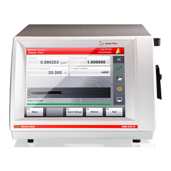
2 DMA 4100/4500/5000 M – An Overview 2.1 Functional Components View of the front and right side Fig. 1: View of the front and right side of DMA 5000 M 1 Power on LED 4 Xsample slot cover plate 2 Color PCAP touch screen 5 Sample inlet and outlet 3 Syringe holder (DMA 5000 M only) 6 Air pump outlet... - Page 10 2 DMA 4100/4500/5000 M – An Overview Rear view Fig. 3: Rear view 1 “DRY AIR BLOCK” connectors 8 Power switch 2 USB interface 9 Fuse holder 3 VGA interface 10 Power inlet 4 RS-232 interface (COM) 11 UL test mark 5 Ethernet interface 12 Type plate with serial number 6 CAN interface...
-
Page 11: Installing The Instrument
3 Installing the Instrument 3 Installing the Instrument 3.2 Mounting the Injection Adapters To install the instrument, put it on a bench, mount injection adapters and hoses, and connect the instrument to the AC power supply. Define general 1. Take two injection adapters with screws from instrument settings and perform an air/water check the accessory kit. -
Page 12: Checking For Leak Tightness
3 Installing the Instrument 3.3 Checking for Leak Tightness Connecting the waste vessel by a silicone hose (DMA 4100/4500 M) 1. For DMA 5000 M: Insert the adapters Luer ¼" 1. Screw an adapter UNF ¼" Luer (from the UNF into the openings of the injection adapters. accessory kit) into the threaded hole in the cap 2. -
Page 13: Connecting The Cooling
3 Installing the Instrument 3.6 Switching the Instrument On/Off Connecting the filling hose (DMA 5000 M) 1. Screw an adapter Luer ¼" UNF (from the accessory kit DMA 5000 M) into the top connector of the syringe holder. WARNING 2. Screw one end of the hose 140x3x2 PTFE 2x¼"- High voltage at parts of the instrument can cause 28 UNF (from the accessory kit DMA 5000 M) serious injuries or death. -
Page 14: Instrument Settings And First Checks
(standard), and adjusting the instrument DMA M Model Tolerance constants in a way that the known correct results are found by the instrument. DMA 4100 M 0.0002 g/cm Usually, for a successful adjustment, at least two DMA 4500 M 0.0001 g/cm... -
Page 15: Performing Checks
4 Checking, Adjusting, and Calibrating 4. Perform the following settings: 2. Highlight a custom check and tap <Edit> to open the three-step “Check Administration” - Use the check box “GxP relevant” to define wizard. whether the check is relevant for “Good Practice”... -
Page 16: Adjustments
4 Checking, Adjusting, and Calibrating When to do air checks - Lower limit - Upper limit Use the air check to verify the efficiency of your - Measured value cleaning and drying procedure. We recommend - Check result performing an air check every day after the - Set temperature for the density cell measurements have been finished and the 4. - Page 17 4 Checking, Adjusting, and Calibrating The air/water adjustment takes 5–10 minutes if the of the CIPM formula. Outside the CIPM range of instrument is already clean and dry and equilibrated validity, the IAPWS formula is the preferred method to 20 °C. for obtaining accurate densities of water.
-
Page 18: Defining And Using Methods
5 Defining and Using Methods - Deviation to reference value using new 8. Check the recommendation on the screen and adjustment constants select one of the options <Reject>, <Print>, or <Apply>. 5 Defining and Using Methods Each method contains the following kind of For details on the settings of the measuring information: methods, see the Reference Guide. -
Page 19: Measuring
6 Measuring • For measurements of lubricants according to calculations for product group D with temperature correction to 15 °C Lubricants (API) • Output fields: API Density 15 °C, Density, API Specific Gravity 15 °C, Density Temperature, °API Gravity 15 °C, Density Condition, U-View™ •... - Page 20 6 Measuring NOTICE Samples with a moderate tendency to corrode borosilicate glass, such as strong alkali solutions (e.g. caustic soda), can be measured with the DMA M. • However, take care to remove such samples immediately after measurement, and rinse the measuring cells thoroughly.
-
Page 21: Performing Measurements
6 Measuring 6.3 Performing Measurements 5. Mount a valve or hose clamp at the outlet silicone hose. 6. Close the valve and fill your sample into the To speed up measurements funnel. • Automatic sample naming: See General 7. Fill the measuring cell by carefully opening the Software Functions Manual, section 6.3. -
Page 22: Cleaning And Storing The Instrument
7 Cleaning and Storing the Instrument 7 Cleaning and Storing the Instrument To assure a constant and high accuracy of your Recommended for aqueous samples and measurements, employ a regular and effective beverages: water (cleaning liquid 1) and non- cleaning routine, and store the instrument under the denatured ethanol (cleaning liquid 2). -
Page 23: Cleaning The Instrument Housing And The Touch Screen
(ethanol at appendix A.2 (in case of uncertainties get in 20 °C: approx. 5 min., acetone at 20 °C: contact with Anton Paar GmbH); approx. 3 min.). • aggressive sample residues on the instrument If the ambient humidity is > 90 % rel. humidity, are decontaminated and removed. -
Page 24: Appendix A: Technical Data
Appendix A: Technical Data Appendix A: Technical Data A.1: Measuring Performance Table 1: Technical data of measuring performance DMA 4100 M DMA 4500 M DMA 5000 M Measuring range density 0 to 3 g/cm Measuring range dyn. viscosity 10 to 3000 mPa·s Repeatability s.d. -
Page 25: A.2: General Technical Data
Appendix A: Technical Data Table 3: Precision classes Precision class Stability temperature Stability density Ultrafast < 0.1 °C for 10 s < 0.000005 g/cm for 15/45 s Fast < 0.05 °C for 10 s < 0.000005 g/cm for 60 s Standard <... -
Page 26: A.3: Wetted Parts
Appendix A: Technical Data NOTICE Connect only Anton Paar equipment or equipment with a maximum power consumption of 40 W to the CAN interface. Otherwise the instrument will not work. A.3: Wetted Parts The following materials are in contact with samples and cleaning liquids:... -
Page 27: Appendix B: Measuring Special Samples
Appendix B: Measuring Special Samples Appendix B: Measuring Special Samples B.1: Degassing Samples 1. Boil the liquid for several minutes to remove dissolved air. 2. Fill the boiled liquid into a clean glass flask and There are different methods to degas liquid sam- cover it. -
Page 28: Appendix C: Measuring Under Special Conditions
Appendix C: Measuring under Special Conditions Appendix C: Measuring under Special Conditions C.1: Measuring at High Temperatures WARNING Leaky components of the measuring system can WARNING cause sample to splash out when pressure is applied to the measuring system. Injuries and Risk of leakage risk of fire possible. -
Page 29: Appendix D: Maintenance And Repair
Instrument Repairs” and must be cleaned before return. To exchange the protection foil TIP: Find the contact data of your local Anton Paar 1. Remove the old protection foil. representative on the Anton Paar website 2. Use a soft tissue, which can be wetted with (http://www.anton-paar.com) under “Contact”. -
Page 30: Appendix F: Eu Declaration Of Conformity
Appendix F: EU Declaration of Conformity Appendix F: EU Declaration of Conformity XDLIB017EN-E...
Need help?
Do you have a question about the DMA 4100 M and is the answer not in the manual?
Questions and answers