Anton Paar DMA 4100 M Instruction Manual
Hide thumbs
Also See for DMA 4100 M:
- Instruction manual (152 pages) ,
- Instruction manual and safety information (30 pages)

Related Manuals for Anton Paar DMA 4100 M


Summary of Contents for Anton Paar DMA 4100 M
- Page 1 Measure what is measurable and make measurable that which is not. Galileo Galilei (1564-1642) Instruction Manual DMA 4100 M DMA 4500 M DMA 5000 M instrument software version: from 2.70 (original instruction)
- Page 3 Instruction Manual DMA 4100 M DMA 4500 M DMA 5000 M instrument software version: from 2.70 (original instruction)
- Page 4 Changes, copyright, trademarks etc. This document and its contents may be changed or amended by Anton Paar at any time without prior notice. All rights reserved (including translation). This document, or any part of it, may not be reproduced, changed, copied, or distributed by means of electronic systems in any form (print, photocopy, microfilm or any other process) without prior written permission by Anton Paar GmbH.
-
Page 5: Table Of Contents
Contents 1 About the Instruction Manual ........................ 7 2 Safety Instructions..........................8 3 Measuring Principle..........................10 4 The Instrument – Overview ........................11 5 Checking the Supplied Parts ....................... 12 6 Functional Components........................15 6.1 View of the Front and Right Side ....................15 6.2 View of the Left Side ........................ - Page 6 10 Measuring ............................37 10.1 Sample Name ..........................37 10.2 Filling Samples..........................37 10.3 Performing Measurements......................39 10.4 Filling and Measurement Errors ....................40 10.4.1 Status Messages ........................40 10.4.2 Error Messages........................40 11 Cleaning and Storing the Instrument ....................41 11.1 Cleaning and Drying the Measuring Cell ..................
-
Page 7: About The Instruction Manual
1 > Menu paths are written in instruction manual from Anton Paar GmbH, these menu level 2 italics. Menu levels are must be treated as part of the instruction manual. -
Page 8: Safety Instructions
• Use the instrument only for the purpose (e.g. use safety goggles, gloves, respiratory described in the instruction manual. Anton Paar protection, etc.). GmbH is not liable for damages caused by incorrect use of the instrument. - Page 9 Anton open flames, at a safe distance from the Paar GmbH. instrument. • For repairs, contact your local Anton Paar • Place the instrument on a laboratory bench representative. The instrument must not be made of fireproof material, preferably bricks, returned without the filled out "Safety...
-
Page 10: Measuring Principle
3 Measuring Principle 3 Measuring Principle Definition of density and specific gravity Concentration measurement The density ρ of a sample is defined as mass In binary mixtures, the density of the mixture is a divided by volume: function of its composition. Thus, the density value of a binary mixture can be used to calculate its ... -
Page 11: The Instrument - Overview
This Measurement is based on the oscillating U-tube issue is addressed by Anton Paar with two new method that has been invented at a research features: institute in Graz, Austria, and first introduced onto •... -
Page 12: Checking The Supplied Parts
2. Check the delivery for completeness by comparing the supplied parts to those listed in table 5-1. 3. If a part is missing, contact your Anton Paar representative. 4. If a part is damaged, contact the transport company and your Anton Paar representative. - Page 13 5 Checking the Supplied Parts Table 5-1: Supplied parts Symbol Pcs. Article description Mat. no. Accessory kit DMA / DMA M 159958 containing: Hose 3x5 mm silicone (transparent) 50814 only for pressures up to 0.4 bar rel. Syringe 2 mL Luer 51974 Injection adapter Luer black 159026...
- Page 14 5 Checking the Supplied Parts Table 5-2: Optional parts Article description Mat. no. Data handling Keyboard German USB 80809 Keyboard USA USB 80807 Printer RS-232C incl. cable 9600N81 44737 Printer Epson TM-U220D 93362 RS-232 connection cable D-Sub 9-pin, 3 m 70429 Gender changer DB9M/DB9M 302592...
-
Page 15: Functional Components
6 Functional Components 6 Functional Components 6.1 View of the Front and Right Side Fig. 6-1: View of the front and right side of the DMA M 1 Power on LED 4 Sample inlet and outlet 2 Color PCAP touch screen 5 Air pump outlet 3 Xsample slot cover plate 6.2 View of the Left Side... -
Page 16: Rear View
6 Functional Components 6.3 Rear View Fig. 6-3: Rear view 1 S-BUS interfaces 9 Power switch 2 USB interface 10 Fuse holder 3 VGA interface 11 Power inlet 4 RS-232 interface (COM) 12 UL test mark 5 Ethernet interface 13 Type plate with serial number 6 CAN interface 14 Fan 7 "DRY AIR IN AIR PUMP"... -
Page 17: Operating Elements On The Main Screen
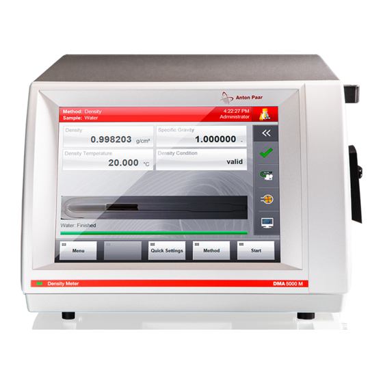
6 Functional Components 6.4 Operating Elements on the Main Screen Fig. 6-4: Main screen example 1 Header 4 Progress bar 2 Output field 5 Buttons area 3 Content area 6 Quick access area Header stay frozen on the screen until the next measurement is started. - Page 18 6 Functional Components Quick access area Function Opens the message list. The general instrument status as well as all measuring errors that have occurred during the measurements of the currently active sample list are described in this list. The button changes its appearance depending on the current error status: Green OK sign: The general instrument status and the...
-
Page 19: Operating Elements On The Menu Screen
6 Functional Components 6.5 Operating Elements on the Menu Screen To access the menu, tap <Menu> on the main screen. Fig. 6-6: Menu screen examples A1 Header B1 <Add to Favorites> button A2 Menu level 1 B2 Buttons area A3 <Back> button B3 Content area A4 <Home>... -
Page 20: Installing The Instrument
7 Installing the Instrument 7 Installing the Instrument 7.2 Mounting the Injection Adapters To install the instrument, put it on a bench, mount injection adapters and hoses, and connect the instrument to the mains supply. Define general 1. Take two injection adapters Luer with screws instrument settings and perform an air/water check from the accessory kit. -
Page 21: Checking For Leak Tightness
7 Installing the Instrument 7.3 Checking for Leak Tightness 7.4 Mounting the Hoses 1. Close one adapter tightly with a male Luer plug. To connect the waste vessel 2. Use a plastic syringe from the accessory kit to inject, with moderate pressure, air through the other adapter. -
Page 22: Switching The Instrument On/Off
7 Installing the Instrument 7.5 Switching the Instrument On/Off 7.6 Instrument Settings and First Checks After having installed the hardware, set the date and WARNING time, see General Software Functions Manual, High voltage at parts of the instrument can cause section 6.1.1. -
Page 23: Checking, Adjusting, And Calibrating
5. Tap <Next> and perform the following settings: DMA M Model Tolerance Select a quantity and the corresponding unit. DMA 4100 M 0.0002 g/cm Define the check tolerance by the "Lower DMA 4500 M 0.0001 g/cm limit"... -
Page 24: Performing Density Checks
8 Checking, Adjusting, and Calibrating To edit a custom check When to do air checks 1. Tap <Menu> and select Setup > Expert Settings Use the air check to verify the efficiency of your > Check Management to open the check cleaning and drying procedure. -
Page 25: Viewing, Printing, Or Exporting Current Check Data
8 Checking, Adjusting, and Calibrating For custom checks: 3. Tap <OK> to start the auto air check. Lower limit If the auto air check succeeds, fill the sample Upper limit into the measuring cell and start your Measured value measurement by tapping <OK>. Check result If the auto air check fails, you can take 4. -
Page 26: Adjustments
8 Checking, Adjusting, and Calibrating 8.3 Adjustments NOTICE You have to readjust the instrument after 8.3.1 Performing an Air/Water Adjustment changing the selected air and/or water table. 1. Tap <Menu> and select Setup > Measuring An air/water adjustment has to be performed if the System Settings >... -
Page 27: Performing A Temperature Range Adjustment
8 Checking, Adjusting, and Calibrating The atmospheric pressure displayed is 2. Follow the instructions on the screen. measured automatically by a built-in sensor. 3. Check that the water is filled without air bubbles. 6. Tap <OK>. TIP: If the water was filled without air bubbles, you The air adjustment routine is carried out. -
Page 28: Performing An Atmospheric Pressure Sensor Adjustment
8 Checking, Adjusting, and Calibrating 8.3.5 Performing Special Adjustments 4. For filling the high-density standard and the two viscosity standards, follow the instructions on the screen. 8.3.5.1 Special Adjustments After the adjustment with the high-density standard, select <Visc. Standard 1> and after Special adjustments are user-specific adjustments the adjustment with the first viscosity standard for special density units, concentrations and... -
Page 29: Special Adjustment For The Canadian Excise Alcohol Table
8 Checking, Adjusting, and Calibrating 8.3.5.2 Special Adjustment for the Canadian To perform a special adjustment Excise Alcohol Table 1. Tap <Menu> and select Checks/Adjustments > Other Adjustments > Density Module > Special To use the output quantity "Canadian Excise Adjustments. -
Page 30: Viewing, Printing Or Exporting Adjustment History: Kb Graph
8 Checking, Adjusting, and Calibrating To print or export all adjustment data 2. Activate the "Density Module" check box and tap <OK>. 1. Tap <Menu> and select Data Memory > Adjustment Data > Print or Export Adjustment NOTICE Data. Factory default reference values for the density of air and water are based on the formula of 2. -
Page 31: Calibrating
8 Checking, Adjusting, and Calibrating 8.4 Calibrating To perform a calibration 1. Perform a density check with water. The goal of a calibration is to validate the accuracy 2. If necessary, carry out an air/water adjustment of the density measurement. at 20 °C. -
Page 32: Defining And Using Methods
9 Defining and Using Methods 9 Defining and Using Methods 9.1 Measuring Methods Factory preset methods The DMA M is delivered with a set of 10 predefined Each method contains the following kind of methods covering the most common applications. information: The measuring temperature for these 10 methods is Instrument settings... -
Page 33: Changing Methods
9 Defining and Using Methods • For measurements of fuel oil according to calculations for product group B with temperature correction to 15 °C • Output fields: API Density 15 °C, Density, API Specific Fuel Oil (API) Gravity 15 °C, Density Temperature, °API Gravity 15 °C, Density Condition, U-View™... -
Page 34: Defining The Measurement Mode
9 Defining and Using Methods 9.2.2 Defining the Measurement Mode For each method, you can set the measurement mode that will be applied when measuring samples. Table 9-1: Measurement modes S (Standard) To perform a standard measurement C (Check) To perform one of the predefined checks. MM (Multiple Measurements) To perform 2 to 10 measurements of a single sample automatically. - Page 35 Predetermined 1 °C all models Settings > method name > Measurement Mode. Equilibrium 0.02 °C DMA 4100 M 2. To select "RM (Repeated Mode)", highlight the DMA 4500 M item and tap <OK>. • Equilibrium fast 0.02 °C 3. Tap "Repeated Mode Settings".
-
Page 36: Defining Formula Parameters
9 Defining and Using Methods Parameter "Density API Product Group" 1. Tap <Menu> and select Methods > Method Settings > method name >Measurement Mode. The API Product Group can be set to A (crude oil), 2. To select "TS (Temperature Scan)", highlight the B (fuels) or D (lubes) to set up measuring methods item and tap <Next>. -
Page 37: Measuring
10 Measuring 10 Measuring 10.2 Filling Samples In this chapter, the filling of samples and the measuring procedure including the detection of bubbles are described. To achieve highly accurate measuring results, fill the samples into the measuring cell homogeneously and without bubbles. WARNING In the unlikely case of malfunction or damage of WARNING... - Page 38 10 Measuring Important for high accuracy measurements To fill with a syringe (Luer tip) If you use a syringe to fill the instrument, we NOTICE recommend using a 2 mL syringe only to fully utilize Do not use syringes that contain lubricants. The the instrument’s accuracy (especially with lubricants can dissolve into your sample and DMA 5000 M).
-
Page 39: Performing Measurements
10 Measuring 10.3 Performing Measurements To fill with a peristaltic pump NOTICE To speed up measurements • The liquid levels in the sample container and waste container must be below the filling level Automatic sample naming: See General Software of the instrument. Never put the peristaltic Functions Manual, section 6.3. -
Page 40: Filling And Measurement Errors
10 Measuring 10.4 Filling and Measurement Errors 10.4.2 Error Messages Automatic bubble detection 10.4.1 Status Messages (FillingCheck™) If a bubble has been detected anywhere in the U- Density condition tube in real time, the "Density Condition" output field The "Density Condition" output field gives shows "Filling Warning"... -
Page 41: Cleaning And Storing The Instrument
11 Cleaning and Storing the Instrument 11 Cleaning and Storing the Instrument To assure a constant and high accuracy of your Cleaning liquid 2 removes cleaning liquid 1 measurements, employ a regular and effective and is easily evaporated by a stream of dry cleaning routine, and store the instrument under the air in order to accelerate drying of the cell. -
Page 42: Storing The Instrument
The instrument must not be returned without the filled out "Safety Declaration for Instrument Repairs" and must be cleaned before return. TIP: Find the contact data of your local Anton Paar representative on the Anton Paar website (http://www.anton-paar.com) under "Contact". C76IB003EN-N... -
Page 43: Appendix A: Technical Data
Appendix A: Technical Data Appendix A: Technical Data A.1: Measuring Performance Table A-1: Technical data of measuring performance DMA 4100 M DMA 4500 M DMA 5000 M 0 to 3 g/cm Measuring range 0.00005 g/cm 0.00001 g/cm 0.000001 g/cm Repeatability density (s. d.) 0.02 °C... -
Page 44: A.2: General Technical Data
EN 61140 or with SELV (safety extra-low voltage) according to EN 60950. NOTICE Connect only Anton Paar equipment or equipment with a maximum power consumption of 40 W to the CAN interface. Otherwise, the instrument will not work. -
Page 45: A.3: Wetted Parts
Appendix A: Technical Data A.3: Wetted Parts The following materials are in contact with samples and cleaning liquids: DMA M Material Part Borosilicate glass Measuring cell PTFE Filling adapter Standard accessories Material Part Polyethylene Waste vessel Polypropylene/Polyethylene Syringe 2 mL Luer PTFE Injection adapter Luer PTFE... -
Page 46: Appendix B: Measuring Special Samples
Appendix B: Measuring Special Samples Appendix B: Measuring Special Samples B.1: Degassing Samples To use an ultrasonic bath • Put your sample for approx. 5–10 minutes into There are different methods to degas liquid an ultrasonic bath until bubbling ceases. samples. - Page 47 Appendix B: Measuring Special Samples Liquids in aerosol cans For the quality control of aerosol cans, you can use the Anton Paar Aerosol Adapter (Mat. No. 74650) to fill the liquid safely and conveniently into your DMA M. For details, see the Aerosol Adapter instruction manual.
-
Page 48: Appendix C: Measuring Under Special Conditions
Appendix C: Measuring under Special Conditions Appendix C: Measuring under Special Conditions C.1: Measuring at High Humidity/Low For a measuring temperature of 20 °C, a drying cartridge must be used under the following Temperature Conditions conditions: If the ambient air contains humidity and the Relative air humidity measuring temperature is lower than the ambient Ambient temperature... -
Page 49: C.2: Measuring At Low/High Temperatures
Appendix C: Measuring under Special Conditions Moist silica gel can be regenerated: Pour the silica DMA M to an external thermostat or tap water line gel into a glass bowl and blow hot, dry air (max. that is delivering water at a constant temperature 130 °C / 266 °F) through it for approx. -
Page 50: C.3: Measuring At High Pressures
Appendix C: Measuring under Special Conditions C.3: Measuring at High Pressures Adjustment with air and water To reach the highest possible accuracy for high The supplied silicone hose and injection adapters pressure measurements, perform the air adjustment can only be used at atmospheric pressure. Before as usual at ambient pressure and the water applying high pressures, exchange the supplied adjustment or an adjustment with any other... -
Page 51: Appendix D: Camera Settings
Appendix D: Camera Settings Appendix D: Camera Settings D.1: Adjusting the Camera Position D.2: Setting the Camera Illumination If the camera does not show the complete If the illumination of the camera picture is not measuring cell, you can adjust the position of the suitable for your special environment, you can camera. -
Page 52: Appendix E: Trouble Shooting
Appendix E: Trouble Shooting Appendix E: Trouble Shooting Table E-1: Adjustment Problem Cause and Correction Readjustment is necessary Bad water quality for checks/adjustments: Use freshly section 8.3.1 very often. degassed ultra-pure (bi-distilled or deionized) water. The measuring cell is not clean: Clean and dry the section 11 measuring cell perfectly before an air check/adjust- ment. - Page 53 Appendix E: Trouble Shooting Table E-2: Measurement Problem Cause and Correction The measuring times during a The measuring times during temperature scans can temperature scan are varying. vary due to internal temperature measurements and calibration after changing the temperature by a defined value.
- Page 54 Appendix E: Trouble Shooting Table E-7: Printout problems Problem Cause and Correction No printout on office printer Office printer problems: Check if the printer has enough paper, toner, etc. See the respective printer instruction manual. The office printer type is not supported by your General instrument.
-
Page 55: Appendix F: Output Quantities And Live Raw Data
Appendix F: Output Quantities and Live Raw Data Appendix F: Output Quantities and Live Raw Data F.1: Output Quantities The following quantities can be selected as output for the output fields. Group: System DataField 1 Name of the user-defined data field (optional sample ID). DataField 2 Name of the user-defined data field (optional sample ID). - Page 56 Group: Density Number of digits displayed with density values: DMA 5000 M: 6 DMA 4500 M: 5 DMA 4100 M: 4 Number of digits displayed with temperature values: DMA 5000 M: 3 DMA 4500 M: 2 DMA 4100 M: 2...
- Page 57 Number of digits displayed with ethanol values: DMA 5000 M: 3 DMA 4500 M: 2 DMA 4100 M: 2 Canadian Excise Alcohol Table Special ethanol table converting the output of a special adjustment into an ethanol value.
- Page 58 Concentration of extract/sugar (sucrose) of beverages in different concentration units. Number of digits displayed with concentration values: DMA 5000 M: 3 DMA 4500 M: 2 DMA 4100 M: 2 Number of digits displayed with Mass Concentration Sugar: All 3 models: 1 Baumé...
- Page 59 (mol/L) according to different tables. Number of digits displayed with % w/w values: DMA 5000 M: 3 DMA 4500 M: 2 DMA 4100 M: 2 Number of digits displayed with mol/L and N values: DMA 5000 M: 4 DMA 4500 M: 3...
- Page 60 (group D). Number of digits displayed with API density values: DMA 5000 M: 5 DMA 4500 M: 4 DMA 4100 M: 4 Number of digits displayed with °API Gravity values: DMA 5000 M: 3 DMA 4500 M: 2 DMA 4100 M: 2 °API Gravity 15 °C...
-
Page 61: F.2: Live Raw Data
Appendix F: Output Quantities and Live Raw Data F.2: Live Raw Data For viewing and printing live raw data as well as for a list of software specific live raw data refer to the General Software Functions Manual, section 10.8. DMA Density Quantities not mentioned in the following table are described in the tables above (e.g. -
Page 62: Appendix G: List Of Quick Settings Parameters
–25 and 95 °C (or 90 °C). Density Measurement Predetermination default finished by Equilibrium (for DMA 4100 M / DMA 4500 M) Equilibrium fast (for DMA 5000 M) Equilibrium medium Equilibrium slow None (use method default) Density Timeout Set the timeout for density measurement (30–3600 s, default 600 s). - Page 63 Appendix G: List of Quick Settings Parameters Parameter Type Parameter Select Description Density API Product A - Crude oil default Group B - Fuels D - Lubes None (use method default) Density API Input Density default Quantity Density (not visc. - corr.) Special Adjustment up to 5 None (use method default)
-
Page 64: Appendix H: Density Tables
Appendix H: Density Tables Appendix H: Density Tables NOTICE The factory default reference values for the density of air and water are based on the formula of Spieweck and Bettin and cover the whole measuring range of the instrument. Density of Air For the temperature t [in °C] and the pressure p [in mbar or hPa] the density ρ... - Page 65 Appendix H: Density Tables Density of Water (0 °C to 95 °C) Formula for the calculation of the density of water • according to Spieweck/Bettin: t -------------------------------- b t = 9.998 395 2 ·10 kg/m –1 = 1.695 257 7 ·10...
- Page 66 Appendix H: Density Tables Density of water Density of water Density of water T °C T °C T °C CIPM/ Spieweck/ CIPM/ Spieweck/ CIPM/ Spieweck/ IAPWS 95 Bettin IAPWS 95 Bettin IAPWS 95 Bettin 0.999843 0.999840 0.992215 0.992212 0.971790 0.971785 0.999902 0.999899 0.991830...
-
Page 67: Appendix I: Instrument Software Versions
Appendix I: Instrument Software Versions Appendix I: Instrument Software Versions Instrument Date of Document software Comments release number version V1.00 18.06.2008 C76IB01A First version released V1.10 14.08.2008 C76IB01B Users with administrator rights can update the operating system and adjust the camera position. V1.52 27.02.2009 C76IB01C... - Page 68 Appendix I: Instrument Software Versions Instrument Date of Document software Comments release number version V2.00 10.09.2010 C76IB003EN-A • GUI performance improved • Data browser filter: only users and methods used are available • More detailed information about firmware module state during startup (new initialization screen instead of online screen) •...
- Page 69 Appendix I: Instrument Software Versions Instrument Date of Document software Comments release number version V2.20 12.09.2011 C76IB003EN-C • New system security settings implemented: different security levels, electronic signature, auto logoff and password expiry • "Audit Trail" menu now in the "System Security" menu •...
- Page 70 Appendix I: Instrument Software Versions Instrument Date of Document software Comments release number version V2.30 24.05.2012 C76IB003EN-F • Redesign of graphical user interface C76IB003EN-G • New filter criteria: time, measurement mode • Notification emails • New measurement modes: Multiple Filling, Temperature Table Scan, Repeated Mode •...
-
Page 71: Appendix J: Calibration Approval
Appendix J: Calibration Approval Appendix J: Calibration Approval The software of the instrument consists of several parts (system software, graphical user interface, Module Firmware version result determination, data storage, etc.). Essential DSP-SAC 9.004.017 for the measurement and calculation of the density is the firmware of the DSP-SAC module. -
Page 72: Appendix K: Declaration Of Conformity
Appendix K: Declaration of Conformity Appendix K: Declaration of Conformity C76IB003EN-N... -
Page 73: Appendix L: Menu Tree
Appendix L: Menu Tree Appendix L: Menu Tree The menu tree shows which parts of the menu are accessible for users with administrator, manager or operator rights using the following colors: Administrator Administrator, Manager Administrator, Manager, Operator Checks/Adjustments Checks Air/Water Adjustment Other Adjustments Density Module Air/Water Adjustment... - Page 74 Appendix L: Menu Tree Setup Measuring System Settings Density Module Sample List Sample List / Sample Settings User-defined Data Fields Sample List Warnings Mandatory Data Fields Camera Air Pump Temperature Extrapolation Settings Control Panel Date and Time Regional Settings Input Units Printer Management Network Instrument Name and Location...
- Page 75 Appendix L: Menu Tree Service Backup Instrument Settings Restore Instrument Settings Update System Update Module Firmware Update Install Language Pack Logging Configuration System Information IQ/OQ Report Export Instrument Data Full System Backup Full System Restore Live Raw Data DMA Density Calculations DCB - Air Pump DCB - Air Pressure...
- Page 76 Index Index apparent specific gravity 56 Symbols atmospheric pressure sensor 28 °Balling 58 auto air check 25 °Brix 58 °Plato 58 <Menu> button 17 <Method> button 17 Baumé 58 <Quick Settings> button 17 bubble detection 38 <Sample List> button 17 <Start>...
- Page 77 Index formula 10 of water 65 gas bubbles 11 density (not visc.-corr.) 56 density check check results 25 check/SOP data 25 performing 24 performing a density check 24 HCl 43 density condition 56 high humidity/low temperature conditions 48 density tables 64 HM C&E 58 density temperature 56 display...
- Page 78 Index measuring at low temperatures 49 repeatability 43 measuring cell 11 reproducibility 46 measuring errors 40 residues 38 measuring methods definition 32 factory preset methods 32 maximum number 33 sample amount 38 measuring mode 17 sample changer 14 measuring range 43 sample name 37 measuring settings sample status 40...
Need help?
Do you have a question about the DMA 4100 M and is the answer not in the manual?
Questions and answers