Table of Contents
Advertisement
Quick Links
Instructions/Parts
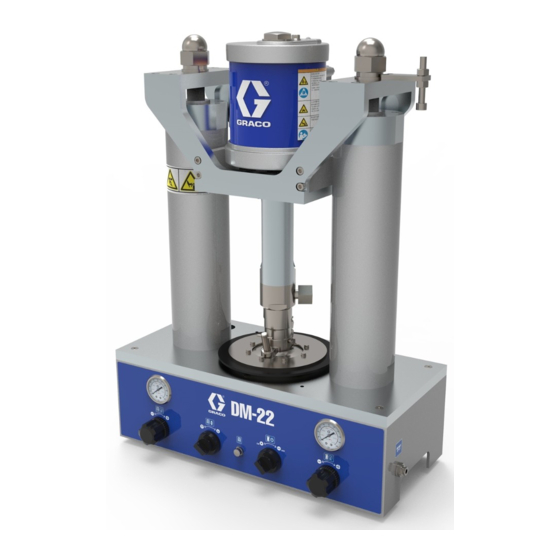
22:1 Ratio Stainless Steel
DM-22 Supply System
Used for precision dispense of single component viscous materials for 300 CC (0.3 liter),
600 CC (0.6 liter) and 1 Gallon (3.79 liter) containers. For professional use only.
Not approved for use in European explosive atmosphere locations.
Part No. 25T471, 300 CC
Part No. 25T472, 600 CC
Part No. 25T473, 1 Gallon
Includes Pump and Ram
2200 psi (15.2 MPa, 152 bar) Maximum Fluid Working Pressure
100 psi (0.7 MPa, 7 bar) Maximum Air Inlet Pressure
Important Safety Instructions
Read all warnings and instructions in this
manual before using the equipment. Save
these instructions.
300 CC
600 CC
3A7931B
1 Gallon
EN
Advertisement
Table of Contents

Related Manuals for Graco DM-22


Summary of Contents for Graco DM-22
- Page 1 Instructions/Parts 22:1 Ratio Stainless Steel DM-22 Supply System 3A7931B Used for precision dispense of single component viscous materials for 300 CC (0.3 liter), 600 CC (0.6 liter) and 1 Gallon (3.79 liter) containers. For professional use only. Not approved for use in European explosive atmosphere locations.
-
Page 2: Table Of Contents
California Proposition 65 ....27 Graco Standard Warranty ....28... -
Page 3: Warnings
Warnings Warnings The following warnings are for the setup, use, grounding, maintenance, and repair of this equipment. The exclama- tion point symbol alerts you to a general warning and the hazard symbols refer to procedure-specific risks. When these symbols appear in the body of this manual or on warning labels, refer back to these Warnings. Product-specific hazard symbols and warnings not covered in this section may appear throughout the body of this manual where applicable. - Page 4 Warnings FIRE AND EXPLOSION HAZARD Flammable fumes, such as solvent and paint fumes, in work area can ignite or explode. Paint or sol- vent flowing through the equipment can cause static sparking. To help prevent fire and explosion: • Use equipment only in well ventilated area. •...
- Page 5 Warnings BURN HAZARD Equipment surfaces and fluid that is heated can become very hot during operation. To avoid severe burns: • Do not touch hot fluid or equipment. PERSONAL PROTECTIVE EQUIPMENT Wear appropriate protective equipment when in the work area to help prevent serious injury, including eye injury, hearing loss, inhalation of toxic fumes, and burns.
-
Page 6: Typical Installation
Typical Installation Typical Installation DM-22 Supply System, 300 CC Shown . 1: Typical Installation Key: Main Air Line Supply System Air Line DM-22 Supply System Air Filter (Required, but not supplied) Pressure Regulator Valve (Required, but not supplied) Bleed-type Master Air Valve (Required, but not supplied) -
Page 7: Component Identification
Component Identification Component Identification 25T471, 300 CC . 2: System Components - 300 CC Key: AA Pump AJ Manifolds AB Ground Wire AK Pump Air Pressure Gauge AC Bleed-Type Master Air Switch AL Ram Air Pressure Gauge AD Pump Bleeder Valve AM Pump Bracket AE Pump Air Regulator AN Base... -
Page 8: 25T472, 600 Cc
Component Identification 25T472, 600 CC . 3: System Components - 600 CC Key: AA Pump AJ Manifolds AB Ground Wire AK Pump Air Pressure Gauge AC Bleed-Type Master Air Switch AL Ram Air Pressure Gauge AD Pump Bleeder Valve AM Pump Bracket AE Pump Air Regulator AN Base AF Ram Air Regulator... -
Page 9: 25T473, 1 Gallon
Component Identification 25T473, 1 Gallon . 4: System Components - 1 Gallon Key: AA Pump AN Base AB Ground Wire AP Ram Director Switch AC Bleed-Type Master Air Switch AR Main Air Line Inlet Fitting AD Pump Bleeder Valve AS Pump Fluid Intake Housing AE Pump Air Regulator AT Air Assist Valve (Push Button) AF Ram Air Regulator... -
Page 10: Installation
Contact your Graco distributor for assistance in designing a system to suit your needs. DM-22 Supply System (C): Connect the supplied ground wire and clamp to a true earth ground. 1. Place the system on a hard, level surface. Check that the system is level in all directions. -
Page 11: Connect And Disconnect Air Tubes
System Components and Tubes Accessories Follow these steps when connecting and disconnecting any air tubes on the DM-22 supply system. Connection To help reduce the risk of serious injury when adjust- ing or repairing the pump, the pressure must be 1. -
Page 12: Operation
Procedure when you stop dispensing and before cleaning, checking, or servicing the equipment. 1. Lock the dispense device trigger being used with the DM-22 supply system. Pump Bleeder Valve 2. Disconnect the main air line from the machine. 3. Set the Ram Director Switch (AP) to the “down”... -
Page 13: Flush The System
Operation Flush the System Start and Adjust the Ram The pump will fall to the bottom slowly if shut off the air supply to the ram when the ram is raised. Also, as the ram is raised and lowered, the Wiper Plate (AU) (for 1 Gallon model only), ram tubes, and pump mounting To avoid fire and explosion, always ground equipment bracket move. -
Page 14: Start And Adjust The Pump
Operation Start and Adjust the Pump 4. Set a can of fluid on the ram base, centering it under the Wiper Plate (AU). The air motor piston and fluid piston (located inside the If the can has a welded seam, position it with the seam air motor cylinder and coupling) move when air is sup- facing the rear of the pump to avoid injury due to splat- plied to the motor. - Page 15 Operation 9. Adjust Pump Air Regulator (AE) pressure until the pump starts. Pump Bleeder Valve Bleed Hole . 10: Pump Bleeder Valve Ram Air Pump Air Ram Director Regulator Switch Regulator NOTE: When changing fluid containers after the initial priming, open the Pump Bleeder Valve (AD) to re-prime Ram Air Bleed-Type Master the pump and vent any trapped air before new fluid...
-
Page 16: Prime The Pump And Pump Fluid
Operation Prime the Pump and Pump Fluid 2. Set the Ram Air Regulator (AF) to below 30 psi (0.21 MPa, 2.1 bar). 1. Ensure the Pump Air Regulator (AE) is closed, then 3. Open the dispensing valve and relieve all fluid pres- set the Ram Air Regulator (AF) to about 22 psi (0.15 sure in the system. -
Page 17: Shutdown And Care Of The Pump
Recycling and Disposal Recycling and Disposal Shutdown and Care of the Pump End of Product Life At the end of the product’s useful life, dismantle and recycle it in a responsible manner. • Perform the Pressure Relief Procedure on page NOTICE Never leave water or water-based fluid in a carbon •... -
Page 18: Troubleshooting
Troubleshooting Troubleshooting 1. Follow the Pressure Relief Procedure, on page 12, before checking or repairing the system. 2. Check all possible problems and causes before disassembling system. Problem Cause Solution Pump fails to operate. Restricted line or inadequate air Clear; increase air supply. Ensure supply;... -
Page 19: Repair
Repair Repair Disassembly 10. Unscrew the wet-cup/packing nut. Remove the u-cup packing (215) from the throat. Remove the washer (216) from the wet-cup/packing nut. 11. Unscrew the piston rod housing (232). Remove the u-cup packing (215) from the fluid housing (203). 12. -
Page 20: Reassembly
Repair Reassembly 8. Thread the fluid piston (201) into the shaft of the air motor (418) until the holes line up. Use the screw (213) to turn the fluid piston, if necessary. Once the NOTE: Lubricate all packings and o-rings with a com- holes in the air motor shaft and fluid piston are patible grease before reassembling. - Page 21 Repair Air Motor shield (406) is in the groove on both the top and bot- tom covers. NOTE: For easier reassembly, start with the top cover (210) turned over on the workbench and assemble the air motor upside-down. 1. Lubricate and install the o-ring (402) on the top cover (410).
-
Page 22: Parts
Parts Parts For 1 Gallon Model Only Apply adhesive (200 series) to threads, per directions on Lips face down. packet. Lips face up. Lubricate inside surface of cylinder with grease. Torque to 30-35 ft-lb (41-47 N•m). Torque to 35-40 ft-lb (47-54 N•m). Torque to 298-314 in-lb (35-37 N•m). - Page 23 Parts Ref. Part Description Qty. Ref. Part Description Qty. 247391 VALVE, pilot (pack of 2) CU7051 ASSEMBLY, pump bracket, 300 24P018 VALVE, air; includes items 409 CC, model 25T471 and 411 (qty 4) CU7085 ASSEMBLY, pump bracket, 600 15M213 MUFFLER CC, model 25T472 15M227 RING, retaining 1) 2)
-
Page 24: Accessory
Dimensions 25T471, 300 CC Raised: Fluid Outlet 31.5 in. (800 mm) 1/4 npt(f) Lowered: 22.7 in. (550 mm) Air Inlet 8 mm(f) 14.2 in. (360 mm) 11.8 in (300 mm) . 15: DM-22 Supply System Dimensions - 300 CC 3A7931B... -
Page 25: 25T472, 600 Cc
1/4 npt(f) 23.6 in. (600 mm) Air Inlet 8 mm(f) 14.2 in. (360 mm) 11.8 in (300 mm) . 16: DM-22 Supply System Dimensions - 600 CC 25T473, 1 Gallon Fluid Outlet 1/4 npt(f) Raised: 32.3 in. (820 mm) Lowered: 22.4 in. -
Page 26: Technical Specifications
Length Diameter Diameter If the cartridge size or material is different, If the cartridge size or material is different, please contact with Graco sales representa- please contact with Graco sales representa- tive for custom solution. tive for custom solution. 3A7931B... -
Page 27: California Proposition 65
California Proposition 65 California Proposition 65 CALIFORNIA RESIDENTS WARNING: Cancer and reproductive harm – www.P65warnings.ca.gov. 3A7931B... -
Page 28: Graco Standard Warranty
With the exception of any special, extended, or limited warranty published by Graco, Graco will, for a period of twelve months from the date of sale, repair or replace any part of the equipment determined by Graco to be defective.
Need help?
Do you have a question about the DM-22 and is the answer not in the manual?
Questions and answers