Upright LX31 Service Manual
Electric and bi-energy models
Hide thumbs
Also See for LX31:
- Service & parts manual (188 pages) ,
- Service manual (120 pages) ,
- Operator's manual (41 pages)

Related Manuals for Upright LX31


Summary of Contents for Upright LX31
- Page 1 LX31 / LX41 Electric and Bi-Energy Models Serial Numbers 4022 - Current P/N 067448-023...
- Page 2 LX31 / LX41 Electric and Bi-Energy When contacting UpRight for service or parts information, be sure to include the MODEL and SERIAL NUMBERS from the equipment nameplate. Should the nameplate be missing, the SERIAL NUMBER is also stamped on top of the chassis above the front axle pivot.
- Page 4 SUOMI SVENSKA DANSK NORSK ESPAÑOL NEDERLANDS ENGLISH DEUTSCH FRANCAIS ITALIANO...
- Page 5 This manual consists of five (5) parts. P E R A T O R A N U A L A copy of the Operator Manual that is stored on every UpRight Aerial Work Platform. 1 - G E C T I O N...
- Page 6 Foreword OTES Page ii Service Manual...
- Page 7 NEVER charge batteries near sparks or open flame. Charging batteries emit explosive hydrogen gas. Modifications to the aerial work platform are prohibited or permissible only at the approval by UpRight. AFTER USE, secure the work platform from unauthorized use by turning both keyswitches off and removing key.
-
Page 8: Table Of Contents
067449-023 LX31/LX41 Electric and BiEnergy ONTENTS Introduction ................3 General Description . -
Page 9: Introduction
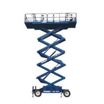
Introduction 067449-023 LX31/LX41 Electric and BiEnergy NTRODUCTION This manual covers the operation of the LX 31 and LX 41 Electric and BiEnergy machines. This manual must be stored on the machine at all times. ENERAL ESCRIPTION Figure 1: LX Serie7s Work Platform 1. -
Page 10: Special Limitations
067449-023 LX31/LX41 Electric and BiEnergy Special Limitations PECIAL IMITATIONS O D E L S Travel with the platform raised is limited to a creep speed range. Elevating of the Work Platform is limited to firm, level surfaces only. D A N G E R The elevating function shall ONLY be used when the work platform is level and on a firm surface. -
Page 11: Controls And Indicators
Controls and Indicators 067449-023 LX31/LX41 Electric and BiEnergy ONTROLS AND NDICATORS Figure 2: Controls and Indicators Platform Controls Chassis Controls 1 Steering Switch 2. Interlock Lever Switch 3. Control Lever 1 Emergency Stop 7. Start Button 4. Outrigger Switches 2. Platform/Chassis Switch 8. -
Page 12: Pre-Operation & Safety Inspection
067449-023 LX31/LX41 Electric and BiEnergy Pre-Operation & Safety Inspection & S PERATION AFETY NSPECTION NOTE: Carefully read, understand and follow all safety rules, operating instructions, labels and National Safety Instructions/Requirements. Perform the following steps each day before use. 1. Open modules and inspect for damage, fluid leaks or missing parts. - Page 13 System Function Inspection 067449-023 LX31/LX41 Electric and BiEnergy 7. Depress the interlock lever switch and push the steering switch RIGHT then LEFT to check for steering control. 8. Optional Outrigger Equipped Machines: a. With the Lift/Outrigger/Drive switch in DRIVE, depress the interlock lever switch on the control lever and position each Outrigger switch to the EXTEND position.
-
Page 14: Operation
067449-023 LX31/LX41 Electric and BiEnergy Operation PERATION NOTE: Before operating the work platform, ensure that the pre-operation and safety inspection has been completed, any deficiencies have been corrected, and the operator has been thoroughly trained on this machine. W A R N I N G Never operate the work platform with the parking brakes released. -
Page 15: Travel With Work Platform Elevated
Operation 067449-023 LX31/LX41 Electric and BiEnergy R A V E L W I T H O R K L A T F O R M L E V A T E D Travel with the platform elevated ONLY on firm and level surfaces. -
Page 16: Leveling The Platform (Outrigger Equipped Machines Only)
067449-023 LX31/LX41 Electric and BiEnergy Operation E V E L I N G T H E L A T F O R M U T R I G G E R E Q U I P P E D M A C H I N E S O N L Y W A R N I N G When using outriggers, all four (4) outriggers must be in firm contact with the supporting surface. -
Page 17: Towing Or Winching
Towing or Winching 067449-023 LX31/LX41 Electric and BiEnergy OWING OR INCHING Perform the following only when the machine will not operate under its own power and it is necessary to move the machine or when winching onto a transport vehicle (see “Transporting the Work Platform” on page 13). -
Page 18: Fold Down Guardrails
067449-023 LX31/LX41 Electric and BiEnergy Fold Down Guardrails UARDRAILS This procedure is only for passing through doorways. Guardrails must be returned to proper position before using the machine. Figure 6: Fold Down Guardrails O L D O W N R O C E D U R E NOTE: When performing the following procedures, retain all fasteners. -
Page 19: Transporting The Work Platform
Transporting the Work Platform 067449-023 LX31/LX41 Electric and BiEnergy RANSPORTING THE LATFORM R E P A R A T I O N F O R H I P M E N T 1. Fully lower the platform. 2. Disconnect the battery negative (-) lead from the battery terminal. -
Page 20: Maintenance
067449-023 LX31/LX41 Electric and BiEnergy Maintenance AINTENANCE L O C K I N G T H E L E V A T I N G S S E M B L Y Figure 8: Blocking Elevating Assembly W A R N I N G... -
Page 21: Battery Maintenance
Always wear safety glasses when working with batteries. Battery fluid is highly corrosive. Thoroughly rinse away any spilled fluid with clean water. Always replace batteries with UpRight batteries or manufacturer approved replacements weighing 48 kg (106 lbs.) each. Eight 6 Volt Batteries... -
Page 22: Engine And Generator (Bienergy Models)
067449-023 LX31/LX41 Electric and BiEnergy Maintenance N G I N E A N D E N E R A T O R N E R G Y O D E L S Figure 11: Engine OOLANT The coolant recovery tank is mounted on the inside of the door of the power module. -
Page 23: Preventative Maintenance Schedule
Preventative Maintenance Schedule 067449-023 LX31/LX41 Electric and BiEnergy REVENTATIVE AINTENANCE CHEDULE The complete inspection consists of periodic visual and operational checks, along with periodic minor adjustments to assure proper performance. Daily inspection will prevent abnormal wear and prolong the life of all systems. The inspection and maintenance schedule is to be performed at regular intervals. -
Page 24: Labels
067449-023 LX31/LX41 Electric and BiEnergy Labels ABELS These labels shall be present and in good condition before operating the work platform. Be sure to read, understand and follow these labels when operating the work platform. WARNING TIPPING HAZARD 064936-099 Check tire pressure daily. - Page 25 Labels 067449-023 LX31/LX41 Electric and BiEnergy Figure 13: Safety Labels Locations Platform Controls Rear Power Module Control Module Front Inside Chassis Controls Operator Manual Page 19...
-
Page 26: Specifications
067449-023 LX31/LX41 Electric and BiEnergy Specifications PECIFICATIONS Specifications subject to change without notice. Refer to the Service Manual for service and repair infor- mation. Refer to the Parts Manual for illustrated parts breakdown. Hot weather or heavy use may reduce performance. - Page 27 Table 1-5: Specific Gravity and Battery Voltage ......... 1-13 Table 1-6: Battery Charging, UpRight Electric and BiEnergy Machines ..... . . 1-14 Table 1-7: Battery Charger Troubleshooting .
-
Page 28: Hazard Indicators
UpRight, Inc., might be done, or of the possible hazardous consequences of each conceivable way, nor could UpRight Inc. investigate all such ways. Anyone using service procedures or tools, whether or not recommended by UpRight Inc., must satisfy themselves thoroughly that neither personal safety nor... -
Page 29: Torque Specifications
O M P O N E N T S NOTE: Always lubricate threads with clean hydraulic fluid prior to installation Use the following values to torque hydraulic components used on UpRight Aerial Work Platforms. Table 1-1: Torque Specifications for Hydraulic Components... -
Page 30: Table 1-3: Torque Specifications For Metric Fasteners, U.s. Customary Units
Torque Specifications Section 1 - General Information Table 1-3: Torque Specifications for Metric Fasteners, U.S. Customary Units 10.9 12.9 Grade 12.9 Grade 10.9 Grade 8.8 Nominal Tightening Torque Tightening Torque Tightening Torque Clamp Clamp Clamp Thread Load Load Load K =,15 K =,20 K =,15 K =,20... -
Page 31: Date Code Identification On Hoses
• Optimizer with adapter (UpRight P/N 100329-000) • Flow Meter Kit (UpRight P/N 067040-000) • Quadragauge with fitting (UpRight P/N 063971-000) • 0-25 kg (0-50 Lbs.) Chain Tension Scale (UpRight P/N 107078-000) IGHT • Gland Nut Wrench (UpRight P/N 062521-000) •... -
Page 32: Upright Connectors
UpRight Connectors Section 1 - General Information 1-6 U IGHT ONNECTORS UpRight connectors are designed so that connector parts, contacts or electrical cables may be replaced without replacing the entire connector. Figure 1-1: UpRight Connector Kits Small Kit Large Kit... -
Page 33: Figure 1-4: Locking Finger, Upright Connector
E L E A S I N G O C K I N G I N G E R S Figure 1-4: Locking Finger, UpRight Connector 1. The Locking Fingers can be released following the removal of the Locking Wedge of either the male or female connector. -
Page 34: Hydraulic Manifold Repair
Hydraulic Manifold Repair Section 1 - General Information 1-7 H YDRAULIC ANIFOLD EPAIR E M O V A L Refer to the Service and Repair section for model specific information. 1. Disconnect the battery. 2. Tag and disconnect the solenoid valve leads. 3. -
Page 35: Cylinder Repair
Section 1 - General Information Cylinder Repair 1-8 C YLINDER EPAIR W A R N I N G Cylinders may be very heavy. Support heavy cylinders before removing pins which secure the cylinder to the machine. E M O V A L NOTE: Refer to the Service and Repair section for the location of cylinders, and the Parts Manual for a list of parts which secure the cylinders. -
Page 36: Electric Motors
Electric Motors Section 1 - General Information 1-9 E LECTRIC OTORS R O U B L E S H O O T I N G Figure 1-6: Electric Motor Service 1. Read the nameplate to become familiar with Ammeter the motor, especially the rated voltage. Power 2. -
Page 37: Figure 1-7: Electric Motor Brushes
Section 1 - General Information Electric Motors N S P E C T I O N Once the motor has been disassembled, go through the following check-list steps to determine where the problem lies. 1. Bearings should spin smoothly and easily and have ample lubrication and be free of corrosion. 2. -
Page 38: Battery Maintenance
Battery fluid is highly corrosive. Thoroughly rinse away any spilled fluid with clean water. Always replace batteries with UpRight batteries or manufacturer approved replacements. Before disconnecting the battery negative (-) lead, make sure all switches are OFF. If ON, a spark will occur at the ground terminal which could cause an explosion if hydrogen gas or fuel vapors are present. -
Page 39: Table 1-5: Specific Gravity And Battery Voltage
A T T E R Y H E C K Electric UpRight Aerial Work Platforms use deep cycle batteries. If poor service life is experienced, batter- ies should be checked for bad cells. Fully charge batteries for 14 hours minimum, ensuring that the charger has completed its cycle (see ‘Battery Charging”... -
Page 40: Table 1-6: Battery Charging, Upright Electric And Bienergy Machines
4. Connect the other end of the extension cord to a grounded AC outlet of proper current, voltage and fre- quency rating. 5. The charger turns on automatically after a short delay. Table 1-6 illustrates charging indicators. Table 1-6: Battery Charging, UpRight Electric and BiEnergy Machines Charger Display AC Charging Current... -
Page 41: Table 1-7: Battery Charger Troubleshooting
If the problem is not resolved after going through the entire table, the charger should be replaced. NOTE: The majority of chargers returned to UpRight as “failed” test good. Please follow the troubleshooting procedures carefully. Table 1-7: Battery Charger Troubleshooting... -
Page 42: Floor Loading
Localized Pressure or Occupied Pressure. To calculate Floor Loading, find the Total Weight of the machine. TOTAL WEIGHT = MACHINE WEIGHT + MAXIMUM PLATFORM CAPACITY. Refer to the machine specifications or contact UpRight or your UpRight dealer. O C A L I Z E D R E S S U R E ²... -
Page 43: Hydraulic Fluid
Unless recommended by UpRight, do not mix hydraulic fluids of different brands or types. The required additives and fluid viscosities may vary. If the use of hydraulic fluids other than listed below is desired please contact UpRight Product Support. OBILFLUID •... -
Page 44: Long Term Storage
Long Term Storage Section 1 - General Information 1-13 L TORAGE NOTE: Do not drain the hydraulic system prior to long term storage. If the machine is to be placed in long term storage, follow these recommended preservation procedures. R E S E R V A T I O N 1. -
Page 45: Table Of Contents
This section contains instructions for the maintenance of the machine. Refer to the General Information section for information relevant to all UpRight work platforms. Referring to the Operator Manual will aid in understanding the operation and function of the various components and systems of the machine, and help in diagnosing and repair of the machine. - Page 46 Fuel Tank, Bi-Energy Models ............. . 2-32 Page 2-2 067448-023 LX31/LX41 Electric and Bi-Energy Work Platform | European Specifications...
-
Page 47: Ist Of Igures
Figure 2-28: Fuel Tank, Bi-Energy Models............2-32 067448-023 LX31/LX41 Electric and Bi-Energy Work Platform | European Specifications... -
Page 48: General Description
12. Outrigger Control Manifold (optional) 13. Brake Manifold 14. Batteries 15. Level Sensor 16. Outrigger Relay Box (optional) 17. Proximity Switch 18. Diesel Fuel Tank 19. Diesel Motor and Generator Page 2-4 067448-023 LX31/LX41 Electric and Bi-Energy Work Platform | European Specifications... - Page 49 Section 2 - Service and Repair General Description Figure 2-1: LX Electric and Bi-Energy Component Location UARDRAILS NOT SHOWN POWER MODULE FRONT REAR CONTROL MODULE 067448-023 LX31/LX41 Electric and Bi-Energy Work Platform | European Specifications Page 2-5...
-
Page 50: Preventative Maintenance
The preventative maintenance table has been designed for machine service and maintenance repair. Please photocopy the following page and use the table as a checklist when inspecting the machine for ser- vice. Page 2-6 067448-023 LX31/LX41 Electric and Bi-Energy Work Platform | European Specifications... -
Page 51: Preventative Maintenance Check List
Check lug nuts (torque to 205 Nm [150 ft. Tires lbs.]) Lubricate Check Tire Pressure (5 bar [75 PSI]) Daily Check for peeling, missing, or unreadable Labels Daily labels & replace 067448-023 LX31/LX41 Electric and Bi-Energy Work Platform | European Specifications Page 2-7... -
Page 52: Blocking The Elevating Assembly
2. Rotate maintenance brace clockwise until the lock- ing pin engages. 3. Press the Lower Button to completely lower the platform. Page 2-8 067448-023 LX31/LX41 Electric and Bi-Energy Work Platform | European Specifications... -
Page 53: Lubrication
90° fitting on the side. Plug the 90° fitting. 7. Replace the fill plug. 8. Install the torque hub (refer to “Torque Hub Installation” on page 2-21). 067448-023 LX31/LX41 Electric and Bi-Energy Work Platform | European Specifications Page 2-9... -
Page 54: Hydraulic Fluid Reservoir And Filter
N G I N E Change oil filter and fuel filter after every 100 hours of operation. Refer to the engine manufacturer docu- mentation that was included with the machine. Page 2-10 067448-023 LX31/LX41 Electric and Bi-Energy Work Platform | European Specifications... -
Page 55: Setting Hydraulic Pressures
5. Press the Steering Switch to the left and hold until the system bypasses. 6. Turn the Steering Relief Valve adjustment screw clockwise until the gauge reads 105 bar (1500 PSI). 7. Replace the cap on the Steering Relief Valve. 067448-023 LX31/LX41 Electric and Bi-Energy Work Platform | European Specifications Page 2-11... -
Page 56: Switch Adjustments
8. Turn the Drive Speed Switch to HI SPEED and attempt to drive the machine. • If the machine will drive faster than 0,8 km/h (0.5 mph), the switch is out of adjustment. 9. Lower the work platform completely. Page 2-12 067448-023 LX31/LX41 Electric and Bi-Energy Work Platform | European Specifications... -
Page 57: Removal And Installation, Serial Number 4022-4274
9. Deploy the maintenance brace. Loosen the bracket adjustment screws and move the switch up to increase or down to decrease the platform height. Tighten the adjustment screws. 10. Repeat Step 5. through Step 8.. 067448-023 LX31/LX41 Electric and Bi-Energy Work Platform | European Specifications Page 2-13... -
Page 58: Proximity Switch - Serial Number 4275-Current
2. Turn the Drive Speed Switch to HI SPEED and attempt to drive the machine. • If the machine will drive faster than 0,8 km/h (0.5 mph), the switch is out of adjustment or defective. Page 2-14 067448-023 LX31/LX41 Electric and Bi-Energy Work Platform | European Specifications... -
Page 59: Removal And Installation, Serial Number 4275-Current
9,5 mm (0.375 in.) maximum. 7. Remove the clamp and guide and repeat Step 5. and Step 6. of “Test the Proximity Switch, Serial Number 4275-Current” on page 2-14). 067448-023 LX31/LX41 Electric and Bi-Energy Work Platform | European Specifications Page 2-15... -
Page 60: Proximity Switch Height Adjustment - Serial Number 4275-Current
6. Deploy the maintenance brace (see “Blocking The Elevating Assembly” on page 2-8). 7. Push the Level Sensor base to test the alarm circuit. The red LED under the Level Sensor should turn ON and the alarm should sound. Page 2-16 067448-023 LX31/LX41 Electric and Bi-Energy Work Platform | European Specifications... -
Page 61: Hydraulic Manifolds
7. Spring, 6,4 mm (0.25 in.) Diameter 8. Plug 9. Orifice 10. Spring, 9,5 mm (0.375 in.) Diameter 11. 90° Fitting, 6MB-6MJ 12. 90° Fitting, 4MB-6MJ 13. 90° Fitting, 4MB-4MJ 067448-023 LX31/LX41 Electric and Bi-Energy Work Platform | European Specifications Page 2-17... -
Page 62: Hydraulic Power Unit
IMMEDIATELY to prevent contamination from dust and debris. 4. Remove capscrews and washers holding the motor and brake to torque hub. 5. Remove the motor. 6. Remove the brake. Page 2-18 067448-023 LX31/LX41 Electric and Bi-Energy Work Platform | European Specifications... -
Page 63: Brake Seal Replacement
7. Depress the electric motor start switch to energize brake hydraulic system. 8. Check for leaks and bleed air out of brake hydraulic system using bleed valve located on brake housing. 067448-023 LX31/LX41 Electric and Bi-Energy Work Platform | European Specifications Page 2-19... -
Page 64: Torque Hub
13. Remove ½-20 nuts and washers from torque hub. 14. Remove torque hub. IMPORTANT: Note position of 90° fitting on torque hub body. Hub must be installed with fitting in same position. Page 2-20 067448-023 LX31/LX41 Electric and Bi-Energy Work Platform | European Specifications... -
Page 65: Torque Hub Installation
Use soap and water on hub to detect location of leaks. If a leak is detected, seal or O-ring must be replaced. RESSING OOLS Use pressing tools to remove the seal, cup and cone. 067448-023 LX31/LX41 Electric and Bi-Energy Work Platform | European Specifications Page 2-21... -
Page 66: Torque Hub Disassembly
15. Turn hub over on larger end. Using a punch and hammer, remove bearing cup from counterbore of hub. Be careful not to strike counterbore. NOTE: Carrier sub-assembly does not need to be disassembled to replace seals. Page 2-22 067448-023 LX31/LX41 Electric and Bi-Energy Work Platform | European Specifications... -
Page 67: Torque Hub Assembly
Repeat steps 6.-9. and remeasure end play (Figure ). 10. Apply a light coat of “Never Seize” to the pipe plugs and install into pipe plug holes in hub. NOTE: Leave hole for 90° fitting open. 067448-023 LX31/LX41 Electric and Bi-Energy Work Platform | European Specifications Page 2-23... -
Page 68: Main Assembly
16. Roll test the unit in both clockwise and counterclockwise directions. Turn hub nine full revolutions in each direction. 17. Leak test the hub at 0,35 bar (5 PSI) for two to three minutes. Page 2-24 067448-023 LX31/LX41 Electric and Bi-Energy Work Platform | European Specifications... - Page 69 5. Spaces, Input 12. Stud 9. Bearing, Cup 4. Thrust Washer 6. sun Gear 13. Pipe Plug 10. Bearing, Cone 5. Retaining Ring 7. Gear, Internal 14. Pipe Plug 067448-023 LX31/LX41 Electric and Bi-Energy Work Platform | European Specifications Page 2-25...
-
Page 70: Drive Motors
IMPORTANT: Be sure screw does not fall inside motor. 5. Remove old brush and replace with new brush. Brush 6. Replace screw, unhook brush spring and return to original position. 7. Install and relatch headband. Screw Page 2-26 067448-023 LX31/LX41 Electric and Bi-Energy Work Platform | European Specifications... -
Page 71: Steering Cylinder
2. Rod Seal 6. Backup Ring 10. Rod Weldment 14. Wear Ring 3. Wear Ring (2 required) 7. O-ring 11. Tube Weldment 4. Retaining Ring 8. Locknut 12. Piston Seal 067448-023 LX31/LX41 Electric and Bi-Energy Work Platform | European Specifications Page 2-27... -
Page 72: Lift Cylinders
5. Install the hoses. 6. Lift and lower the machine for several cycles to work out the air. Check for leaks, repair as necessary. Page 2-28 067448-023 LX31/LX41 Electric and Bi-Energy Work Platform | European Specifications... - Page 73 D. Cylinder E. Set Screw Seal Kit Includes: 1 Rod Wiper 2. Rod Seal 3. Wear Ring 4. Static Seal 5. Wear Ring 6. Piston Seal 7. Piston Seal 067448-023 LX31/LX41 Electric and Bi-Energy Work Platform | European Specifications Page 2-29...
-
Page 74: Outrigger Cylinder (Optional)
3. Thread the wires for the pressure Switch and the ball Switch through the strain relief. 4. Reattach the wires to the Switches exactly as disassembled. 5. Tighten strain relief. 6. Install plug to top of outrigger cylinder. Page 2-30 067448-023 LX31/LX41 Electric and Bi-Energy Work Platform | European Specifications... - Page 75 7. Foot Pad 12. Static Seal #1 3. Piston 8. Counterbalance Valve 13. Piston Seal 4. Seal Retainer 9. Foot Pad Bolt 5. Head Cap 10. Rod Wiper 067448-023 LX31/LX41 Electric and Bi-Energy Work Platform | European Specifications Page 2-31...
-
Page 76: Generator, Bi-Energy Models Only
The fuel tank is located in the control module on Bi-Energy models. 1 Fuel Tank 2. Hose Fitting, 3/ 3. Hose Fitting, 1/4 4. Fuel Cap 5. Drain Plug 6. Withdrawal Tube 7. Bushing Page 2-32 067448-023 LX31/LX41 Electric and Bi-Energy Work Platform | European Specifications... - Page 77 Upright Traction Controller display ........
-
Page 78: Technical Support
Use the charts on the following pages to help determine the cause of a fault in your UpRight work platform NOTE: Spike protection diodes at components have been left out of the charts to eliminate confusion. -
Page 79: Electric Truth Tables
(Bi-Energy) Charge Relay Serial #4022-4274 | Brake Release Relay Serial #4275–Up | (Bi-Energy) 12V Charge Relay Platform Power Relay Prevent Pump Start Relay (Bi-Energy) Starter Relay (Bi-Energy) Glow Plug Relay 067448-023 LX31/LX41 Electric and Bi-Energy Work Platform | European Specifications Page 3-3... - Page 80 Up Solenoids SOL3 Down Solenoid SOL5 Steer Right Solenoid SOL6 Steer Left Solenoid SOL8 Brake Solenoid SOL11 Brake Release Solenoid SOL12 (Bi-Energy) Stop/Run Solenoid TG1 & TG2 Tachometer-Generator Page 3-4 067448-023 LX31/LX41 Electric and Bi-Energy Work Platform | European Specifications...
-
Page 81: Outrigger Option
Solenoid, Outrigger Extend, Left-Rear OR-SOL4 Solenoid, Outrigger Retract, Left-Rear OR-SOL5 Solenoid, Outrigger Extend, Right-Front OR-SOL6 Solenoid, Outrigger Retract, Right-Front OR-SOL7 Solenoid, Outrigger Extend, Right-Rear OR-SOL8 Solenoid, Outrigger Retract, Right-Rear 067448-023 LX31/LX41 Electric and Bi-Energy Work Platform | European Specifications Page 3-5... -
Page 82: Hydraulic Truth Table
Hydraulic Pump Hydraulic Pump Pressure Switch Main Relief Valve Steering Relief Valve Brake Apply Valve Brake Release Valve Steering Valve Lift Valve Dump Valve Down Valve V7–V10 Outrigger Valve Page 3-6 067448-023 LX31/LX41 Electric and Bi-Energy Work Platform | European Specifications... -
Page 83: Troubleshooting The Mos90
When the MOS90 is pulsing (being used) run time is being incremented and stored. The "dot" in the time display is blinking when MOS90 is being used, steady when idle. 067448-023 LX31/LX41 Electric and Bi-Energy Work Platform | European Specifications Page 3-7... -
Page 84: Calibrator Settings
Tacho Output CL=REV High/Low Speed CL=High OP=Low Direction Flag OP=No Dr. CL=Drv actv. First Error Latch Value= 0-255 Flash Code NOTE: CL = Switch Closed OP = Switch Open Page 3-8 067448-023 LX31/LX41 Electric and Bi-Energy Work Platform | European Specifications... -
Page 85: Mos90 Fault Finding Flow Charts
- Flashes until fault is cleared Check power and control wiring for shorts Check for correct startup sequence. Was direc- tion or lift selected at power up? Rectify Retry Replace Controller 067448-023 LX31/LX41 Electric and Bi-Energy Work Platform | European Specifications Page 3-9... - Page 86 Check power and control wiring Rectify Rectify Check for open circuit motor Check for shorts to frame and battery leakage Rectify Rectify Replace controller Replace MOS90 Controller Page 3-10 067448-023 LX31/LX41 Electric and Bi-Energy Work Platform | European Specifications...
- Page 87 Check pot operation with voltmeter for voltage at Check for battery leakage to frame minimum setting Rectify Adjust as necessary or replace Replace MOS90 Controller Replace MOS90 Controller 067448-023 LX31/LX41 Electric and Bi-Energy Work Platform | European Specifications Page 3-11...
- Page 88 Check mounting and heatsink of controller Replace Rectify Check output voltage from tachometer board, using voltmeter Check application is correct Replace Use larger controller Replace MOS90 Controller Replace MOS90 Controller Page 3-12 067448-023 LX31/LX41 Electric and Bi-Energy Work Platform | European Specifications...
- Page 89 Use calabrator test mode and check platform up switch and severe tilt switch inputs and wiring Rectify Rectify Check output voltage from tachometer using voltmeter Replace MOS90 Controller Replace Replace MOS90 Controller 067448-023 LX31/LX41 Electric and Bi-Energy Work Platform | European Specifications Page 3-13...
- Page 90 Contactor drive S/C. LED resets itself if short Replace MOS90 Controller circuit clears. c) Mosfets did not turn on. Recycle direction to neutral to clear fault indication. Replace controller Page 3-14 067448-023 LX31/LX41 Electric and Bi-Energy Work Platform | European Specifications...
-
Page 91: Activating "Test
• 3.5 VDC = 0% speed input, 0.0 VDC=100% speed input. If set at an extremely high value MOS90 will read as fault and shut down. Properly set the LX31/41 should start to move slowly with a small movement of the Control Handle after a very small "deadband" zone. - Page 92 Activating "TEST" Section 3 - Troubleshooting Figure 3-3: MOS90 Wiring Diagram Page 3-16 067448-023 LX31/LX41 Electric and Bi-Energy Work Platform | European Specifications...
- Page 93 4-10 Component Identification ..........4-22 067448-023 LX31/LX41 Electric and Bi-Energy Work Platform | European Specifications...
-
Page 94: Electrical Schematic, Lx Bi-Energy Serial # 4022-4274
TG1 & TG2 Tachometer - Generator Monitor Drive Motor Speed MOS90”D” Prevent Pump Start Relay Power to Pump Start Switch Upper Controls Starter Relay Power to Starter Motor Engine Assembly MOT5 SOL12 Page 4-2 067448-023 LX31/LX41 Electric and Bi-Energy Work Platform | European Specifications... - Page 95 Electrical Schematic, LX Bi-Energy Serial # 4022-4274 Continued from Previous Page ALM1 SOL1 SOL2 SEN1 RES1 MOT4 MOT3 CONT SOL3 BAT1 ALM2 SOL5 SOL6 MOT1 MOT2 SOL11 SOL8 067448-023 LX31/LX41 Electric and Bi-Energy Work Platform | European Specifications Page 4-3...
- Page 96 12V Charge Relay Activate R14 Lower Control Box TG1 & TG2 Tachometer - Generator Monitor Drive Motor Speed MOS90”D” Platform Power Relay Power to Upper Controls Upper Controls MOT5 SOL12 Page 4-4 067448-023 LX31/LX41 Electric and Bi-Energy Work Platform | European Specifications...
- Page 97 Electrical Schematic, LX Bi-Energy: Serial # 4275-4390 Continued from Previous Page ALM1 SOL1 SOL2 SEN1 RES1 MOT4 MOT3 CONT SOL3 BAT1 ALM2 SOL5 SOL6 MOT1 SOL11 SOL8 MOT2 067448-023 LX31/LX41 Electric and Bi-Energy Work Platform | European Specifications Page 4-5...
-
Page 98: Electrical Schematic, Lx Electric: Serial # 4022-4274
Brake Release Relay Power to Brake Relay R10 Relay Panel TG1 & TG2 Tachometer - Generator Monitor Drive Motor Speed MOS90”D” Platform Power Relay Power to Upper Controls Upper Controls Page 4-6 067448-023 LX31/LX41 Electric and Bi-Energy Work Platform | European Specifications... - Page 99 Electrical Schematic, LX Electric: Serial # 4022-4274 Continued from Previous Page ALM1 SOL1 SOL2 SEN1 MOT4 RES1 CONT MOT3 SOL3 BAT1 ALM2 SOL5 SOL6 MOT1 MOT2 SOL11 SOL8 067448-023 LX31/LX41 Electric and Bi-Energy Work Platform | European Specifications Page 4-7...
- Page 100 Switch Power to SOL11 Lower Control Box TG1 & TG2 Tachometer - Generator Monitor Drive Motor Speed MOS90”D” Power Relay Switch Power to All Relays Lower Control Box Page 4-8 067448-023 LX31/LX41 Electric and Bi-Energy Work Platform | European Specifications...
- Page 101 Electrical Schematic, LX Electric: Serial # 4275-4390 Continued from Previous Page ALM1 SOL1 SOL2 MOT4 SEN1 RES1 MOT3 CONT SOL3 BAT1 ALM2 SOL5 SOL6 MOT1 SOL11 MOT2 SOL8 067448-023 LX31/LX41 Electric and Bi-Energy Work Platform | European Specifications Page 4-9...
-
Page 102: Electrical Schematic, Lx Bi-Energy - Outriggers
OR-SOL6 Retract Solenoid RH-F Control Outrigger Position Outrigger Valve Block TG1 & TG2 Tachometer - Generator Monitor Drive Motor Speed MOS90”D” OR-SOL7 Extend Solenoid RH-R Control Outrigger Position Outrigger Valve Block Page 4-10 067448-023 LX31/LX41 Electric and Bi-Energy Work Platform | European Specifications... - Page 103 OR-SOL5 OR-S12 OR-S13 OR-SOL6 OR-R6 OR-SOL7 OR-R7 OR-SOL8 OR-R8 OR-R9 OR-R16 ALM1 SOL1 SOL2 SEN1 MOT4 MOT3 CONT RES1 SOL3 BAT1 ALM2 SOL5 SOL6 MOT1 SOL11 MOT2 SOL8 067448-023 LX31/LX41 Electric and Bi-Energy Work Platform | European Specifications Page 4-11...
-
Page 104: Electrical Schematic, Lx Electric - Outriggers
Outrigger Pressure Switch Control Outrigger Position RH-F Outrigger TG1 & TG2 Tachometer - Generator Monitor Drive Motor Speed MOS90”D” OR-SOL1 Extend Solenoid LH-F Control Outrigger Position Outrigger Valve Block Page 4-12 067448-023 LX31/LX41 Electric and Bi-Energy Work Platform | European Specifications... - Page 105 OR-S12 OR-SOL5 OR-S13 OR-R6 OR-SOL6 OR-R7 OR-SOL7 OR-R8 OR-SOL8 OR-R9 OR-R16 ALM1 SOL1 SOL2 SEN1 MOT4 MOT3 CONT RES1 SOL3 BAT1 ALM2 SOL5 SOL6 MOT1 MOT2 SOL11 SOL8 067448-023 LX31/LX41 Electric and Bi-Energy Work Platform | European Specifications Page 4-13...
-
Page 106: Wire Routing
Wire Routing Section 4 - Schematics 4-7 W OUTING L E C T R I C Page 4-14 067448-023 LX31/LX41 Electric and Bi-Energy Work Platform | European Specifications... -
Page 107: Bi-Energy
Section 4 - Schematics Wire Routing N E R G Y 067448-023 LX31/LX41 Electric and Bi-Energy Work Platform | European Specifications Page 4-15... -
Page 108: Control Box, Electric
Wire Routing Section 4 - Schematics O N T R O L L E C T R I C Page 4-16 067448-023 LX31/LX41 Electric and Bi-Energy Work Platform | European Specifications... -
Page 109: Control Box, Bi-Energy
Section 4 - Schematics Wire Routing O N T R O L N E R G Y 067448-023 LX31/LX41 Electric and Bi-Energy Work Platform | European Specifications Page 4-17... -
Page 110: Upper Controls, Electric
O N T R O L S L E C T R I C P P E R O N T R O L S N E R G Y Page 4-18 067448-023 LX31/LX41 Electric and Bi-Energy Work Platform | European Specifications... - Page 111 Section 4 - Schematics Wire Routing PPER ONTROLS UTRIGGER PTION NERGY U T R I G G E R P T I O N PPER ONTROLS UTRIGGER PTION LECTRIC 067448-023 LX31/LX41 Electric and Bi-Energy Work Platform | European Specifications Page 4-19...
-
Page 112: Outrigger Option
Over Pressure Protection for the Main Hydraulic Valve, Main Relief Main Valve Block Filter, Return Filter Hydraulic Line Tank Line CYL2 CYL1 ORF2 CYL3 CYL4 CYL5 CYL6 ORF1 OUTRIGGER OPTION Page 4-20 067448-023 LX31/LX41 Electric and Bi-Energy Work Platform | European Specifications... -
Page 113: Hose Routing
Section 4 - Schematics Hose Routing 4-9 H OUTING OUTRIGGER CONTROL OPTION MODULE OUTRIGGER OUTRIGGER OPTION OPTION POWER MODULE OUTRIGGER OUTRIGGER OPTION OPTION 067448-023 LX31/LX41 Electric and Bi-Energy Work Platform | European Specifications Page 4-21... -
Page 114: Component Identification
Terminal Block (Blue or Tan) Bi-Energy c. Terminal Block Ground R15 (S/N 4275-Up) (Yellow or Green) d. Relay, DPDT e. Relay, SPDT Outrigger Option OR-R16 Bi-Energy ALM2 ALM1 Bi-Energy Page 4-22 067448-023 LX31/LX41 Electric and Bi-Energy Work Platform | European Specifications... - Page 115 10. Relays 4. Control Handle 11. Light Board (Outriggers) 5. Interlock Switch 12. Glow Plug Button (Bi-Energy) 6. Rocker Switch (Steering) 13. Key Switch 7. Drive Enable Light 067448-023 LX31/LX41 Electric and Bi-Energy Work Platform | European Specifications Page 4-23...
- Page 116 Figure 4-7: Valve Manifold, Brakes SOL8 Guage Port Plug Brake Release Poppet Valve, N.C. 48VDC Pressure OR-SOL1 ORF1 Switch OR-SOL2 OR-SOL3 OR-SOL4 SOL11 Brake Apply Poppet Valve, N.O. 48VDC Page 4-24 067448-023 LX31/LX41 Electric and Bi-Energy Work Platform | European Specifications...
- Page 117 Call Toll Free in U.S.A. 1-800-926-LIFT...
- Page 118 UpRight, Inc. UpRight 801 South Pine Street Unit S1, Park West Industrial Park Madera, California 93637 Friel Avenue Call Toll Free in U.S.A. Nangor Road TEL: 559-662-3900 Dublin 12, Ireland 1-800-926-LIFT FAX: 559-673-6184 TEL: +353 1 620 9300 PARTS: 1-888-UR-PARTS...
Need help?
Do you have a question about the LX31 and is the answer not in the manual?
Questions and answers